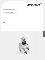
AVENTICS E/P-Pressure Regulator: ND5 VDS Bedienungsanleitung
- Typ
- Bedienungsanleitung

Anwenderhandbuch | application manual
8858903913/10.2014, Replaces: 08.2000, DE/EN
E/P Druckregler NW5
E/P pressure controller ND5
VDS
DeutschEnglish


Deutsch
AVENTICS | VDS | 8858903913–BDL–001–AB 3
Inhalt
Inhalt
1 Einleitung ................................................................................................................................... 5
2 Druckregler ................................................................................................................................ 5
2.1 Schnittstelle ................................................................................................................................................... 5
2.2 Datenformat ................................................................................................................................................... 5
2.2.1 Eingangsdaten .............................................................................................................................................. 5
2.2.2 Ausgangsdaten ............................................................................................................................................. 6
2.2.3 Statusbit .......................................................................................................................................................... 6
2.3 Regler .............................................................................................................................................................. 6
2.4 Anschluss ....................................................................................................................................................... 6
2.4.1 Spannungsversorgung ............................................................................................................................... 6
2.4.2 Datenstecker ................................................................................................................................................. 7
2.4.3 Not-Aus-Situation ........................................................................................................................................ 7
3 Zeichnungen ............................................................................................................................... 7
3.1 Lage der Anschlüsse ................................................................................................................................... 7
4 Zubehör (nicht im Lieferumfang) ............................................................................................. 8
4.1 Anschlusskabel M12-M12 ......................................................................................................................... 8
4.2 Anschlusskabel MiniDIN-M12 .................................................................................................................. 8
4.3 Abschlussstecker ......................................................................................................................................... 8
4.4 Spannungsversorgungsstecker M12 ..................................................................................................... 8
4.5 Grundplatte .................................................................................................................................................... 9
4.6 Busmodule Design C, Design F ................................................................................................................ 9
5 Technische Daten ...................................................................................................................... 9
5.1 Technische Daten Druckregler VDS ....................................................................................................... 9
5.2 Maße Druckregler VDS ............................................................................................................................. 10


AVENTICS | VDS | 8858903913–BDL–001–AB 5
Einleitung
Deutsch
1 Einleitung
Dieses Handbuch beschreibt das Gerät: E/P Druckregler NW5 (VDS) 561 014 154 0
2 Druckregler
Elektropneumatische Druckregelventile wandeln ein elektrisches Signal (Sollwert) in einen
pneumatischen Druck um. Das Druckregelventil kann dabei als reines Stellglied für den Druck
verwendet werden oder die Steuerung bzw. Regelung von anderen Prozessgrößen wie z.B. Kraft
oder Position übernehmen. Die elektrische Ansteuerung der Druckregelventile kann auf
verschiedene Art erfolgen. Das hier beschriebene Gerät benutzt die VDS (Valve Driver System)
Schnittstelle wie sie bei den Busmodulen zur Ansteuerung von Schaltventilen verwendet wird.
2.1 Schnittstelle
Über das Busmodul tauschen die SPS und der Regler Informationen aus. Die SPS sendet dem Regler
die Sollwertinformation und der Regler gibt den Istwert zurück. Vom Regler werden Statusbits an
die SPS zurück gesendet. Die genaue Beschreibung der Daten befindet sich im Kapitel 2.2. Je nach
Typ des Busmoduls können vier (INTERBUS-S, CAN) oder acht (Profibus DP) Regler an das Busmodul
angeschlossen werden. An jedem Anschluss für die Ventileinheit (Strang) können maximal zwei
Druckregler betrieben werden. Eine Mischung von Druckreglern und Ventilen ist möglich. Hierbei ist
zu beachten, daß die Ausrichtung auf Wortgrenzen (Bytegrenzen) für das Druckregelventil
beibehalten wird. Diese Ausrichtung erleichtert die Erstellung des Programms für das
Automatisierungssystem.
2.2 Datenformat
Das Gerät wird mit 16 Bit Eingangs- und 16 Bit Ausgangsdaten vom Busmodul versorgt. Durch die
Wort-Orientierung der Ein- und Ausgabedaten kommt es bei Byte-Orientierten SPS Typen (z.B.
Siemens S5/S7) zu einer Vertauschung von High- und Lowbyte. Wenn für das Datenwort z.B. die
Adresse 30 vergeben wurde, so erscheinen die Bits 0 - 7 in der Byte-Adresse 31.0 - 31.7,
die Bits 8 - 15 in der Byte-Adresse 30.0 - 30.7.
2.2.1 Eingangsdaten
Sollwert 10 Bit (Bit 0 bis Bit 9)
Druckregelung 0 - 10 bar, Auflösung 10 mbar, damit entsprechen 1000 Steps = 10 bar
Alle nicht definierten Bits sind grundsätzlich auf „0“ zu setzen.
Tabelle 1: Sollwert 10 Bit
15 14 13 12 11 10 9 8 7 6 5 4 3 2 1 0
x x x x x x x x x x

6 AVENTICS | VDS | 8858903913–BDL–001–AB
Druckregler
2.2.2 Ausgangsdaten
Istwert 10 Bit (Bit 0 bis Bit 9)
Der Istwert hat die gleiche Auflösung wie der Sollwert.
Druckregelung 0 - 10 bar, Auflösung 10 mbar, damit entsprechen 1000 Steps = 10 bar
2.2.3 Statusbit
Das Statusbit (Bit 15) ermöglicht eine Kontrolle des Datenflusses im Fehlerfall. Es wird immer so
zurückgemeldet wie es gesetzt wurde. Somit kann der Datenfluss im VDS-Strang kontrolliert
werden ohne das ein Sollwert angesteuert werden muss.
2.3 Regler
Der im Gerät vorhandene Regler ist für die Druckregelung erstellt und optimiert worden. Der Regler
vergleicht den von der SPS kommenden Sollwert mit dem Istwert des eingebauten Drucksensors
und regelt die Stellgröße entsprechend nach. Die Parameter des Reglers sind fest vorgegeben und
bedürfen keiner Einstellung. Bei Sollwertvorgaben kleiner 30 mbar steuert das Gerät 0 bar aus. Zur
Reduktion der Temperatur des Magneten wird der Ansteuerstrom reduziert falls der Vordruck am
Ventil zum Ausregeln des Sollwertes zu niedrig ist. Somit braucht das Gerät nicht abgeschaltet zu
werden, wenn die Luftzufuhr kurzzeitig unterbrochen wird.
Die Temperatur des Magneten kann um einiges höher als die Raumtemperatur liegen. Beim
Berühren des Magneten ist daher Vorsicht geboten.
2.4 Anschluss
Der Druckregler wird über drei Stecker angeschlossen. Jedem Stecker ist eine Funktion zugeordnet.
Die Lage der Stecker kann der Zeichnung im Kapitel 3.1 entnommen werden.
2.4.1 Spannungsversorgung
Über den Stecker 1 wird der Regler mit Spannung versorgt. Dabei ist eine externe Sicherung von
M 1,6 A zu verwenden. Die Spannungsversorgung der Schnittstelle erfolgt über das Busmodul.
Der Regler darf nicht mit abgeschalteter Schnittstelle betrieben werden, da in diesem
Zustandkeine Information übertragen werden können.
Abb. 1: Sensorrundstecker M12x1, 5-polig, Einbaustecker
Tabelle 2: Istwert 10 Bit
15 14 13 12 11 10 9 8 7 6 5 4 3 2 1 0
x x x x x x x x x x
Tabelle 3: Statusbit
15 14 13 12 11 10 9 8 7 6 5 4 3 2 1 0
x
5
43
21

AVENTICS | VDS | 8858903913–BDL–001–AB 7
Zeichnungen
Deutsch
2.4.2 Datenstecker
Mit den Steckern 2 und 3 wird der Regler mit dem Busmodul, bzw. mit den weiteren Geräten am VDS
System verbunden. Stecker 2 (Einbaustecker) ist der Dateneingang und Stecker 3 (Einbaubuchse)
ist der Datenausgang. Beide, Stecker und Buchse sind Sensorrundstecker M12x1 in einer 8 poligen
Ausführung. Die Kabel für das VDS müssen geschirmt sein, wobei der Schirm auf der
Überwurfmutter des Steckers / der Buchse angeschlossen sein muss. Im Kapitel 4 (Zubehör) sind
die verfügbaren Kabel aufgelistet.
2.4.3 Not-Aus-Situation
Die Spannungsversorgung des Ventils kann, falls erforderlich, in den Not-Aus Kreis eingebunden
werden. Wird die Spannungsversorgung im Not-Aus Fall unterbrochen, arbeitet die
VDSSchnittstelle des Gerätes weiter, d.h. das Gerät entlüftet im Not-Aus Fall und regelt den Druck
wieder aus, nach dem die Spannungsversorgung wieder am Gerät anliegt.
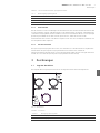
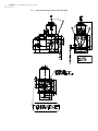
3 Zeichnungen
3.1 Lage der Anschlüsse
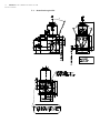
Die folgende Zeichnung zeigt die Anschlüsse und Lage der Stecker des Druckregelventils.
Abb. 2: Anschlüsse
Tabelle 4: Sensorrundstecker M12x1, 5-polig, Einbaustecker
Pin 1 24V Versorgungsspannung Gerät
Pin 2 0 V
Pin 3 nicht belegt
Pin 4 nicht belegt
Pin 5 PE
Tabelle 5: Anschlüsse
Stecker 1 Versorgungsspannung Gerät
Stecker 2 VDS-Eingang
Stecker 3 VDS-Ausgang
1
2
3
VDS-INPUVDS-INPUT VDS-OUTPUTVDS-OUTPUT

8 AVENTICS | VDS | 8858903913–BDL–001–AB
Zubehör (nicht im Lieferumfang)
4 Zubehör (nicht im Lieferumfang)
4.1 Anschlusskabel M12-M12
Für die Verbindung von Geräten, welche mit M12 Stecker/Buchse ausgestattet sind folgende Kabel
erhältlich:
4.2 Anschlusskabel MiniDIN-M12
Für die Verbindung des Druckregelventils mit den Busmodulen Design C ist folgendes Kabel
erhältlich:
Verbindungskabel VDS Busmodul / Regler 1 m 546 042 434 2
4.3 Abschlussstecker
Der Abschlussstecker (Nr.894 100 194 2) wird benötigt, damit der letzte Druckregler im Strang die
Schutzart IP55 erfüllt. Außerdem ist eine VDS-Leitungsprüfung nur mit Abschlussstecker möglich
(siehe auch Beschreibung VDS-Flat Design).
4.4 Spannungsversorgungsstecker M12
Zum Anschluss der Spannungsversorgung ist folgender konfektionierbarer Stecker erhältlich:
W M12 5-polig abgewinkelt Nr. 440 723 001 0
W M12 5-polig gerade Nr. 440 723 002 0
Zusätzlich bieten folgende Hersteller Stecker- und Kabelzubehör an:
W Franz Binder GmbH & Co KG, Postfach 1152, 74172 Neckarsulm
W Richard Hirschmann GmbH & Co, Richard Hirschmann Straße 19, 73728 Esslingen
W Karl Lumberg GmbH & Co, Postfach 1360, 58569 Schalksmühle
W Hans Turck GmbH & Co KG, Witzlebenstr. 7, 45472 Mühlheim / Ruhr
W Vaudeha Elektro GmbH, Gersbeulerstr 20, 58507 Lüdenscheid
Tabelle 6: Verbindungskabel
0,3 m 894 620 285 2
0,5 m 894 620 280 2
1,0 m 894 620 281 2
2,0 m 894 620 282 2
5,0 m 894 620 283 2
10,0 m 894 620 284 2
5,0 m Schleppkettenfähig 894 620 288 2
10,0 m Schleppkettenfähig 894 620 289 2

AVENTICS | VDS | 8858903913–BDL–001–AB 9
Technische Daten
Deutsch
4.5 Grundplatte
Die Grundplatten sind inklusive der dazu gehörigen Montagebausätze
4.6 Busmodule Design C, Design F
Als Busmodule sind folgende Typen lieferbar:
W Profibus DP
W INTERBUS-S
W CAN Open
W Device Net
W RIO (nur F-Design)
Weitere Informationen dazu sind im Druckblatt Nr. 885 890 289 3 zu finden.
5 Technische Daten
5.1 Technische Daten Druckregler VDS
Tabelle 7: Grundplatte
1-fach 561 014 100 2
2-fach 561 014 101 2
3-fach 561 014 102 2
Tabelle 8:
Zulässiges Medium kondensat- und ölfreie Druckluft, gefiltert 50mm
Betriebsdruck maximal 11 bar
Thermischer Anwendungsbereich -20°C...+70°C
Versorgungsspannung 24 V DC +/-20%
Zulässige Oberwelligkeit 5 %
Stromaufnahme maximal 1,3 A
Hysterese und Reproduzierbarkeit 0,06 bar
Auflösung 0,01 bar
Schutzart IP55

10 AVENTICS | VDS | 8858903913–BDL–001–AB
Technische Daten
5.2 Maße Druckregler VDS
α =
0...90
0...90°
±β =
0...90
0...90°

AVENTICS | VDS | 8858903913–BDL–001–AB 11
Contents
English
Contents
1 Introduction .............................................................................................................................. 13
2 pressure controller ................................................................................................................. 13
2.1 interface ........................................................................................................................................................ 13
2.2 data format .................................................................................................................................................. 13
2.2.1 input data ...................................................................................................................................................... 13
2.2.2 output data ................................................................................................................................................... 14
2.2.3 status bit ....................................................................................................................................................... 14
2.3 controller ...................................................................................................................................................... 14
2.4 connection .................................................................................................................................................... 14
2.4.1 power supply ............................................................................................................................................... 14
2.4.2 data plug ....................................................................................................................................................... 15
2.4.3 emergency stop situation ........................................................................................................................ 15
3 drawings ................................................................................................................................... 15
3.1 position of the connections ..................................................................................................................... 15
4 accessories (not part of the delivery) .................................................................................... 16
4.1 VDS cable M12-M12 .................................................................................................................................. 16
4.2 VDS cable MiniDIN-M12 ........................................................................................................................... 16
4.3 terminating resistor .................................................................................................................................. 16
4.4 plug M12 for power supply ..................................................................................................................... 16
4.5 Optional subbases ...................................................................................................................................... 17
4.6 Bus module Design C, Design F ............................................................................................................. 17
5 Technical data .......................................................................................................................... 17
5.1 Technical data pressure controller VDS ............................................................................................. 17
5.2 measurements pressure controller VDS ............................................................................................ 18


AVENTICS | VDS | 8858903913–BDL–001–AB 13
Introduction
English
1 Introduction
This manual describes device: E/P pressure controller ND5 (VDS) 561 014 154 0
2 pressure controller
Electro-pneumatic pressure control valves convert an electronic signal (set value) into a pneumatic
pressure. The pressure control valve can be used as a final component for the pressure or to control
respectively adjust other process variables, as for example to take on power or position. The electric
drive of the pressure control valve can be effected by various ways. The device described here uses
the serial VDS (Valve Driver System) interface as it is also used with the bus modules to drive
switching valves.
2.1 interface
The PLC sends the information about the requested set value to the pressure controller and the
pressure controller returns the actual pressure value. Furthermore status bits are send from the
pressure controller back to the PLC. Detailed description of the data can be found in chapter 2.2.
Depending on the type of the bus module, four (INTERBUS-S, CAN) or eight (profi-bus DP) pressure
controller can be connected to the bus module. With each VDS connection of the bus module
(branch) two pressure controllers maximum can be operated. A mixture of pressure controllers and
valves is possible. In this connection it has to be taken into consideration that the alignment to
integral boundaries (byte boundaries) for the pressure control valve remains the same. The
alignment makes it easier to draw up the program for the automation system.
2.2 data format
The device is supplied by 16 bit input and 16 bit output data coming from the bus module. Because
of word-orientated in- and output data at PLC types which are byte-orientated (e. g. Siemens S5/S7)
an exchange of high- and low byte will occur. If, for example, address 30 has been given to a data
word, the bits 0 - 7 would appear in byteaddress 31.0 – 31.7, the bits 8 – 15 would appear in byte-
address 30.0 – 30.7.
2.2.1 input data
set value 10 Bit (Bit 0 until Bit 9)
pressure control 0 - 10 bar, resolution 10 mbar, 1000 = 10 bar
All non-defined bits have to be always set „0“.
Table 1: set value 10 Bit
15 14 13 12 11 10 9 8 7 6 5 4 3 2 1 0
x x x x x x x x x x

14 AVENTICS | VDS | 8858903913–BDL–001–AB
pressure controller
2.2.2 output data
Actual value 10 Bit (Bit 0 until Bit 9)
The actual value has the same resolution as the set value.
pressure control 0 - 10 bar, resolution 10 mbar, 1000 = 10 bar
2.2.3 status bit
The status bit (bit 15) enables the controlling of the data flow in case of a fault. The check-back
will always be as it has been set.
2.3 controller
The controller integrated in the device has been designed and optimised for the pressure control.
The controller compares the set value given by the PLC with the actual value of the integrated
pressure sensor and will then readjust the manipulated variable accordingly. The parameter of the
controller are prescribed and need not to be regulated. At set values < 30mbar the device adjusts
the control setting to 0bar. The temperature of the magnet will be reduced by reducing the drive
current in case that the input pressure of the valve would be too low to adjust the set value. This way
the device need not to be switched-off, if the air supply is interrupted for a short-term.
The magnet temperature can be much higher than the temperature of the room. Please take
care when touching the magnet.
2.4 connection
The pressure controller will be connected via 3 plugs. Each plug has a certain function. The position
of the plugs can be taken from the diagram in chapter 3.1.
2.4.1 power supply
The controller is supplied via plug 1. An extern protection for M 1,6 A has to be used. The power of
the interface will be supplied via the VDS cable from the bus module.
The controller must not be employed with a switched off interface, as in this state no
information can be transmitted.
Fig. 1: circular sensor connector M12x1, 5-pole, build-in plug
Table 2: actual value 10 Bit
15 14 13 12 11 10 9 8 7 6 5 4 3 2 1 0
x x x x x x x x x x
Table 3: status bit
15 14 13 12 11 10 9 8 7 6 5 4 3 2 1 0
x
5
43
21

AVENTICS | VDS | 8858903913–BDL–001–AB 15
drawings
English
2.4.2 data plug
The controller is connected to the bus module, respectively to other devices of the VDS system via
plugs 2 and 3. Plug 2 (build-in plug) represents the data input and plug 3 (build-in bush) is data
output. Both, plug and bush are circular sensor connectors M12x1 in a 8-pole edition. The cables for
the VDS have to be shielded, whereas the shield has to be connected to the coupling ring of the plug/
the bush. The available cables (accessories) are mentioned in chapter 4.
2.4.3 emergency stop situation
The power supply of the valve can, if necessary, be integrated into the emergency stop circle. If the
power supply is interrupted in an emergency stop case, the VDS-interface will keep on working, this
means in an emergency stop case the device exhausts and will then readjust the pressure, after the
device will once again be supplied.
3 drawings
3.1 position of the connections
The following drawings show the connections and the positions of the plugs of the pressure control
valve.
Fig. 2: connections
Table 4: circular sensor connector M12x1, 5-pole, build-in plug
Pin 1 24V power supply device
Pin 2 0 V
Pin 3 not occupied
Pin 4 not occupied
Pin 5 PE
Table 5: connections
Plug 1 24V power supply of the device
Plug 2 VDS-input
Plug 3 VDS-output
1
2
3
VDS-INPUVDS-INPUT VDS-OUTPUTVDS-OUTPUT

16 AVENTICS | VDS | 8858903913–BDL–001–AB
accessories (not part of the delivery)
4 accessories (not part of the delivery)
4.1 VDS cable M12-M12
The following cables are available for the connection of the devices equipped with M12 VDS
receptacles:
4.2 VDS cable MiniDIN-M12
For the connection of the pressure control valve with the bus modules design C the following cable
is available:
interconnecting cable VDS Bus module / controller 1m 546 042 434 2
4.3 terminating resistor
The terminating resistor (no. 894 100 194 2) is necessary so that the last pressure controller in the
branch will fulfil the protective system IP55. Furthermore a testing of the VDS-line is only possible
using a connector plug (see description VDS-Flat design).
4.4 plug M12 for power supply
For the power supply connection the following prepared plug is available:
W M12 5-pole angled no. 440 723 001 0
W M12 5-pole straight no. 440 723 002 0
In addition the following manufacturers offer plugs- and accessories for cables:
W Franz Binder GmbH & Co KG, Postfach 1152, 74172 Neckarsulm
W Richard Hirschmann GmbH & Co, Richard Hirschmann Straße 19, 73728 Esslingen
W Karl Lumberg GmbH & Co, Postfach 1360, 58569 Schalksmühle
W Hans Turck GmbH & Co KG, Witzlebenstr. 7, 45472 Mühlheim / Ruhr
W Vaudeha Elektro GmbH, Gersbeulerstr 20, 58507 Lüdenscheid
Table 6: VDS cable
0,3 m 894 620 285 2
0,5 m 894 620 280 2
1,0 m 894 620 281 2
2,0 m 894 620 282 2
5,0 m 894 620 283 2
10,0 m 894 620 284 2
5,0 m dragline-able 894 620 288 2
10,0 m dragline-able 894 620 289 2

AVENTICS | VDS | 8858903913–BDL–001–AB 17
Technical data
English
4.5 Optional subbases
Beside of the in-build G1/4 threads for tube fittings the ND5 valve offers the option to be mounted
on a subbase. Three subbase sizes are available. All of them include the necessary sets for the
assembly with pressure controllers.
4.6 Bus module Design C, Design F
The following types are available as bus modules:
W Profibus DP
W INTERBUS-S
W CAN Open
W Device Net
W RIO (only F-Design)
For further information please refer to page no. 885 890 289 3.Technical data.
5 Technical data
5.1 Technical data pressure controller VDS
Table 7: Optional subbases
1-time 561 014 100 2
2-times 561 014 101 2
3-times 561 014 102 2
Table 8:
permissible medium condensate- and oil-free compressed air, filtered 50mm
operating pressure 11 bar maximum
thermal application range -20°C...+70°C
power supply 24 V DC +/-20%
permitted harmonic wave 5 %
drawing of current maximal 1,3 A
hysteresis and consistency 0,06 bar
resolution 0,01 bar
protection system IP55

18 AVENTICS | VDS | 8858903913–BDL–001–AB
Technical data
5.2 measurements pressure controller VDS
α =
0...90
0...90°
±β =
0...90
0...90°


AVENTICS GmbH
Ulmer Straße 4
30880 Laatzen
Phone +49 (0) 5 11-21 36-0
Fax: +49 (0) 511-21 36-2 69
www.aventics.com
Further addresses:
www.aventics.com/contact
The data specified above only serve to
describe the product. No statements
concerning a certain condition or
suitability for a certain application can be
derived from our information. The given
information does not release the user from
the obligation of own judgement and
verification. It must be remembered that
our products are subject to a natural
process of wear and aging.
An example configuration is depicted on
the title page. The delivered product may
thus vary from that in the illustration.
Translation of the original operating
instructions. The original operating
instructions were created in the German
language.
8858903913–BDL–001–AB/10.2014
Subject to modifications. © All rights
reserved by AVENTICS GmbH, even and
especially in cases of proprietary rights
applications. It may not be reproduced or
given to third parties without its consent.
-
 1
1
-
 2
2
-
 3
3
-
 4
4
-
 5
5
-
 6
6
-
 7
7
-
 8
8
-
 9
9
-
 10
10
-
 11
11
-
 12
12
-
 13
13
-
 14
14
-
 15
15
-
 16
16
-
 17
17
-
 18
18
-
 19
19
-
 20
20


AVENTICS E/P-Pressure Regulator: ND5 VDS Bedienungsanleitung
- Typ
- Bedienungsanleitung
in anderen Sprachen
Verwandte Artikel
-
AVENTICS EP-Pressure Controller ED07 290psi VDS - 5610219900 Bedienungsanleitung
-
AVENTICS ED07 Bedienungsanleitung
-
-
-
-
-
-
-
-
Andere Dokumente
-
Naim ND5 XS Schnellstartanleitung
-
Baumer Cable Datenblatt
-
Siko IF09I/1 User Information
-
turck Magnetic Field Sensors …AY1…/RY1 Schnellstartanleitung
-
-
-
-
FALLER 239001/1 Benutzerhandbuch