Parkside PHA 12 A1 Original Instructions Manual
- Typ
- Original Instructions Manual

CORDLESS PLANER PHA 12 A1
AKKU-HOBEL
Originalbetriebsanleitung
CORDLESS PLANER
Translation of the original instructions
IAN 312203

Before reading, unfold the page containing the illustrations and familiarise yourself with all functions
of the device.
Klappen Sie vor dem Lesen die Seite mit den Abbildungen aus und machen Sie sich anschließend mit
allen Funktionen des Gerätes vertraut.
GB / IE / NI Translation of the original instructions Page 4
DE / AT / CH Originalbetriebsanleitung Seite 16

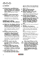
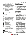
A
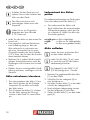
B
C
1 2 3 4 5 6
7
9 10
10
11
11
12
8
12
8
15
15 16
17 7
16
13
14

4
GB IE NI
Introduction
Congratulations on the purchase of your
new device. With it, you have chosen a
high quality product. During production,
this equipment has been checked for quali-
ty and subjected to a nal inspection. The
functionality of your equipment is therefore
guaranteed.
The operating instructions constitute
part of this product. They contain
important information on safety, use
and disposal.
Before using the product, familiarise
yourself with all of the operating
and safety instructions. Use the
product only as described and for
the applications specied. Keep this
manual safely and in the event that
the product is passed on, hand over
all documents to the third party.
Intended use
The cordless planer is suitable for machi-
ning solid wood materials, such as boards
or beams.
The device is part of the Parkside
X12VTEAM series and operates with the
X12VTEAM battery. The batteries may
only be charged using chargers from the
Parkside X 12 V TEAM series.
The device is intended for use by adults.
Children under the age of 16 may not use
the device, except under supervision.
The device is intended to be used by
do-it-yourselfers. It was not designed for
commercial use. The warranty is void in
the case of commercial use.
The manufacturer is not liable for damage
caused by improper use or incorrect ope-
ration.
Content
Introduction .................................4
Intended use ................................4
General description ......................5
Scope of delivery ............................5
Description of functions ....................5
Overview .......................................5
Technical data ..............................5
Safety information .......................6
Symbols used in the instructions .........6
Symbols on the device .....................6
General Safety Instructions
for Power Tools ................................6
Additional safety
instructions for the planer ................10
Initial start-up ............................11
Charging the battery ......................11
Extracting shavings/dust................. 11
Operation ..................................11
Setting the cutting depth .................11
Switching on/off ...........................11
Checking the charge
status of the battery........................12
Working instructions ..................12
Planing.........................................12
Chamfering edges .........................12
Maintenance and Care ...............12
Replacing planer blades ................. 12
Cleaning ....................................13
Storage ......................................13
Disposal/environmental
protection ..................................13
Spare Parts/Accessories .............13
Guarantee .................................14
Repair Service ............................15
Service-Center ............................15
Importer ....................................15
Translation of the original EC
declaration of conformity ........... 31

5
NI
IEGB
General description
An illustration of the most import-
ant functional components can be
found on the front fold-out page.
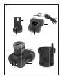
Scope of delivery
First, unpack the device and check for com-
pleteness.
Dispose of the packaging material properly.
• Cordless Planer
• Shavings ejector
• Spanner
• Allen key
• Operating instructions
Description of functions
The cordless planer has a rotating planer
shaft, which is equipped with two blades.
Please refer to the descriptions below for
information on how the operating elements
work.
Refer to the following descriptions for a fun-
ctional description of the controls.
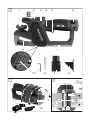
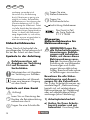
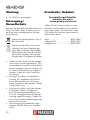
Overview
A
1 Controller, cutting depth adjust-
ment
2 Battery charge level indicator
3 Ventilation holes
4 Safety switch
5 On/off switch
6 Rechargeable battery
7 Planer sole
8 Ejection chute
9 Allen key
10 Spanner
11 Shavings extraction adapter
12 Shavings ejector, left/right
13 V-groove
14 Blade holder, planer blade
15 Nut, blade xing
16 Screw, blade height adjustment
17 Planer blades
Technical data
Cordless Planer ......................PHA 12 A1
Nominal voltage U ...................... 12 V
Idle speed n
0
....................... 14500 min
-1
Protection category...........................IPX0
Weight (incl. battery) .................... 1.5 kg
Cutting depth (10 x 0.2 mm increments)
optimal ................................. 0 - 1 mm
maximum .............................. 1 - 2 mm
Planer width ........................max. 56 mm
Sound pressure level
(L
pA
) .....................79.4 dB(A), K
pA
= 3 dB
Sound power level (L
WA
)
measured ...........90.4 dB(A); K
WA
= 3 dB
Vibration (a
h
) ...... 3.546 m/s
2
; K= 1.5 m/s
2
Levels of noise and vibration were deter-
mined according to the norms and regula-
tions in the declaration of conformity.
The vibration emission value has been mea-
sured according to a standardised testing
method and may be used for comparison
with another power tool.
The indicated vibration emission value may
also be used for an introductory assessment
of the exposure.
Warning: The vibration emission
value whilst actually using the power
tool may vary from the given values
regardless of the type and way in
which the power tool is used.
Try to keep the exposure to vi-
brations as low as possible. An
example of a measure to reduce
vibration exposure is limiting the

6
GB IE NI
working hours. For this purpose all
parts of the operating cycle have to
be considered (for example, times
when the power tool is switched off
and times when it is switched on
but running without any load).
Safety information
This section describes the basic safety rules
when working with the device.
Symbols used in the
instructions
Hazard symbol with infor-
mation on the prevention of
personal injury or property
damage.
Hazard symbol with information on
damage prevention.
Advisory symbol with information on
how to best use the device.
Symbols on the device
Attention!
Read the operating instructions care-
fully before using the device.
Wear safety goggles.
Wear a respiratory mask.
Wear safety gloves.
Direction of travel of planer blade
The device is part of the Park-
side X12VTEAM series
General Safety Instructions
for Power Tools
WARNING! Read all
safety notices, instruc-
tions, illustrations and
technical data that have
been provided with this
power tool. Failure to com-
ply with these and the follo-
wing instructions may result
in electric shock, re and/or
serious injuries.
Save all safety instructions
and guidelines for the fu-
ture.
The term “power tool” used in
the safety instructions refers to
mains-operated power tools
(with a mains cable) and to
battery-operated power tools
(without a mains cable).
1) Occupational Safety
a) Keep your work area
tidy and well lit. Wor-
king in areas that are untidy
or without lighting can result
in accidents.
b) Do not work with the
power tool in a poten-
tially explosive atmo-
sphere where am-
mable liquids, gases or
dust are present. Power
tools generate sparks that
can ignite dust or vapours.
c) Keep children and other
persons away from the
area while the power
tool is in use. Distractions

7
NI
IEGB
can cause you to lose cont-
rol of the power tool .
2) Electrical safety
Caution: This is how to
avoid accidents and inju-
ries from an electric shock:
a) The plug of the power tool
must t into the socket.
The plug must not be mo-
died in any way. Do not
use adapter plugs with
power tools that have a
protective earth. Unmodied
plugs and matching sockets re-
duce the risk of electric shock.
b) Avoid body contact with
earthed surfaces such as
pipes, radiators, cookers
and refrigerators. There
is an increased risk of electric
shock if your body is earthed.
c) Do not expose the power
tool to rain or wet condi-
tions. The penetration of water
into a power tool increases the
risk of electric shock.
d) Never use the power ca-
ble to carry or hang the
power tool or to pull the
plug out of the socket.
Keep the power cab-
le away from heat, oil,
sharp edges and moving
parts. Damaged or untidy po-
wer cables increase the risk of
electric shock.
e) If you are working out-
doors with the power
tool, only use extension
cables that are suitable
for outdoors. Using an ex-
tension cable that is suitable
for outdoors reduces the risk of
electric shock.
f) If operation of the power
tool in a damp environ-
ment is unavoidable,
please use a fault-current
circuit breaker. The use of
a fault-current circuit breaker
reduces the risk of an electric
shock.
3) SAFETY OF PERSONS
a) Pay attention! Be aware of
what you are doing and
take the utmost care when
working with a power
tool. Do not use power
tools if you are tired or
you are under the inu-
ence of drugs, alcohol or
medication. A moment of in-
attention whilst using the power
tool can result in serious injuries.
b) Wear personal protecti-
ve equipment and safety
goggles at all times. Wea-
ring personal protective equip-
ment such as a dust mask, non-
slip safety shoes, hard hat or
ear protection, according to the
type and use of the power tool,
reduces the risk of injury.
c) Avoid starting the power
tool unintentionally. En-
sure that the power tool
is switched off before you
connect it to the power
supply, pick it up or carry
it and/or before you
connect the rechargeable
battery. Having your nger
on the switch of the power tool

8
GB IE NI
while carrying it, or having the
power tool switched on when
connecting it to the power sup-
ply can cause accidents.
d) Remove adjustment tools
or spanners away from
the area before switching
on the power tool. A tool
or key located in a rotating
piece of equipment can lead to
injuries.
e) Avoid an abnormal body
posture. Ensure that your
footing is secure and
keep your balance at all
times. This will help you to
have better control of the pow-
er tool in unexpected situations.
f) Wear suitable clothing.
Do not wear loose clo-
thing or jewellery. Keep
hair, clothes and gloves
away from moving parts.
Loose clothing, jewellery or
long hair may get caught in
moving parts.
g) If dust extraction and
collection devices can be
installed, make sure that
these are connected and
used correctly. Using a dust
collector can reduce hazards
caused by dust.
h) Do not allow yourself to
be lulled into a false fee-
ling of security and do
not disregard the safety
rules for power tools,
even if you are familiar
with the power tool after
using it many times. Care-
less action can lead to serious
injuries within a fraction of a
second.
4) USE AND TREATMENT OF
THE POWER TOOL
a) Do not overload the po-
wer tool. Use the correct
power tool for the job in
hand. With the right power
tool, you can work better and
more safely within the specied
power range.
b) Do not use the power tool
with a damaged cable.
A power tool that no longer
switches on or off is dangerous
and must be repaired.
c) Remove the plug from
the wall socket and/or
remove the rechargeable
battery before you chan-
ge the device’s settings,
change accessories or put
away the power tool.These
safety measures prevent acci-
dentally starting the power tool.
d) Store unused power tools
out of reach of children.
Do not allow persons to
use the power tool who
are not familiar with it or
who have not read the
operating instructions.
Power tools can be dangerous
if operated by inexperienced
persons.
e) Look after the power tool
and accessories carefully.
Check that the moving
parts are working proper-
ly and are not becoming
jammed and that parts
are not broken or dama-
ged in such a way that
the functioning of the de-
vice is impaired. Have da-

9
NI
IEGB
maged parts repaired be-
fore using thepower tool.
Many accidents are caused by
poorly maintained power tools.
f) Keep cutting tools sharp
and clean. Carefully main-
tained cutting tools with sharp
cutting edges are less likely to
get jammed and are easier to
work with.
g) Use the power tool, ac-
cessories etc. in accordan-
ce with these operating
instructions. Take into ac-
count the working condi-
tions and the work to be
carried out. Using the power
tool for anything other than its
intended use can lead to dan-
gerous situations.
h) Keep handles and grip
surfaces dry, clean and
free from oil and grease.
Slippery handles and grip sur-
faces do not permit safe opera-
tion and control over the power
tool in unexpected situations.
5) USE AND TREATMENT OF
THIS BATTERY-POWERED
TOOL
a) Only recharge batteries
using chargers recommen-
ded by the manufacturer.
If a charger that has been de-
signed for a particular type of
battery is used to charge other
batteries, there is a risk of re.
b) Only use batteries that
are intended for the pow-
er tool. The use of other bat-
teries may create a re hazard
and lead to injury.
c) When not in use, keep
batteries away from pa-
per clips, coins, keys,
nails, screws or other
small metal objects that
could cause the contacts
to be bridged. A short circuit
between battery contacts can
result in burns or a re.
d) When misused, uid may
leak from the battery.
Avoid any contact with
it. On accidental contact,
wash in running water. If
the uid comes into con-
tact with the eyes, seek
medical assistance also.
Leaking battery uid can cause
skin irritation or burns.
e) Do not use damaged or
altered batteries. Damaged
or altered batteries can be
unpredictable and lead to re,
explosion or risk of injury.
f) Do not expose batteries
to re or elevated tempe-
ratures. Fire or temperatures
over 130 °C can cause an ex-
plosion.
g) Follow all instructions for
charging and never char-
ge the battery or the bat-
tery-powered tool outside
the temperature range
stated in the operating in-
structions. Incorrect charging
or charging outside the permit-
ted temperature range may des-
troy the battery and increase
the risk of re.

10
GB IE NI
6) SERVICE
a) Only have qualied per-
sonnel repair your power
tool and only use original
spare parts. This ensures the
safety of the device is main-
tained.
b) Never repair damaged
batteries. All battery repairs
should be carried out by the
manufacturer or authorised
customer service centres only.
Additional safety
instructions for the planer
a) Wait for the blade shaft to
come to a stop before put-
ting the power tool down.
An exposed rotating blade shaft
may snag the surface, causing
loss of control and serious in-
jury.
b) Fasten and secure the
workpiece by means of
clamps or with another
method on a stable base.
If you hold the workpiece only
with your hand or against your
own body, it will stay instable
and this can lead to a loss of
control.
c) Do not reach into the
ejection chute with your
hands. Risk of injury from the
planer blades.
d) Always hold the planer
so that it lays at on the
workpiece when working.
The planer could otherwise tilt
and cause injury.
e) The planer should only
be moved over the work-
piece when it is turned on.
There is a risk of kickback if the
planer tilts.
f) Only wood may be
planed, not metal.
g) Harmful dust can occur
when working. Wear a
respiratory mask and attach an
external dust extraction system.
h) In the case of danger,
switch off the planer im-
mediately and remove the
battery from the device.
i) Check the blade regular-
ly for damage. Only use
sharp, undamaged bla-
des.
k) Ensure that the vents are free of
soiling.
l) Remove the battery
- at all times when the user is not
in the vicinity of the machine,
- before the removal of blocka-
ges,
- before checking, cleaning or
working on the machine,
- after touching a foreign body in
order to check the machine for
damage,
- for an immediate check if the
machine begins to vibrate
excessively.
Warning! Observe the
safety information and
notes on charging and
proper use as shown in
the operating instruc-
tions for your battery
and charger from the
Parkside X 12 V Team
series.

11
NI
IEGB
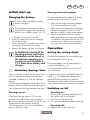
Initial start-up
Charging the battery
If warm, allow the battery to cool
before charging.
Do not expose the battery to direct
sunlight for long periods and do not
place it on a radiator (max. 50 °C).
1.
1. Plug the charger into a socket.
2. Slide the battery (6) into the charging
slot of the charger.
3. Once charging is complete, disconnect
the charger from the mains supply.
4. Remove the battery (6) from the charger.
A detailed description of the
charging process and further
information can be found in
the separate operating ins-
tructions to your Parkside X
12 V Team series battery and
charger.
Extracting shavings/dust
You can use the cordless planer optionally
with an external shavings extractor (not
included in delivery) or with the shavings
ejector.
The shavings are ejected on both sides of the
ejection chute if neither the shavings ejector
nor an external shavings extractor are used.
Shavings ejector
Place the shavings ejector (12) into the
ejection chute (8). Make sure that the gui-
de rails on the shavings ejector (12) t into
the grooves of the ejection chute (8).
The shavings ejector (12) can be tted to
eject to the left or right.
Shavings extraction adapter
The shavings extraction adapter (11) can
be tted to eject to the left or right.
1. Place the shavings extraction adapter
(11) into the ejection chute (8).
Make sure that the part of the shavings
extraction adapter (11) that is in the
ejection chute (8) is open at the bottom.
2. Attach an external extraction system.
Make sure that the dust extraction system
is suitable for the material to be cut. This
information can be found in the opera-
ting instructions of the external device.
Operation
Setting the cutting depth
The best cutting depth for the cordless pla-
ner is between 0 and 1.0 mm.
The cutting depth can be selected by tur-
ning the controller (
1).
The cutting depth can be set in 10 x 0.2
mm increments.
The green area of the scale below the con-
troller (
1) indicates the setting which
removes the least amount of material.
The red area of the scale indicates the setting
which removes the most amount of material.
Switching on/off
Switching on:
1. Press one of the safety switches (4) on
the right or left of the handle.
2. Press the on/off switch (5).
3. You can now release the safety switch (4).
Switching off:
4. Release the on/off switch (5).

12
GB IE NI
Checking the charge status
of the battery
The battery charge indicator ( 2) signa-
lises the state of charge of the battery (
6) while the device is operating. Press and
hold the power button to view.
3 LEDs are on (red, yellow, green):
Battery charged
2 LEDs are on (red, yellow):
Battery partially charged
1 LED is on (red):
Battery needs to be charged
Charge the battery ( 6) when
only the red LED on the level indica-
tor is illuminated.
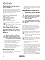
Working instructions
Work safely, giving due con-
sideration to the next steps!
Planing
Attention! Risk of kickback!
Make sure the planer is swit-
ched on before guiding it over
the workpiece to be machined.
· Secure the workpiece to be machined.
· Set the desired cutting depth.
· Place the device’s planer sole and
V-groove onto the workpiece.
· Switch on the device and guide it with
a uniform forward motion over the
workpiece to be machined.
Chamfering edges
The V-groove at the front of the planer sole
is for chamfering edges.
· Place the planer’s V-groove (
13) on
the edge of the workpiece and guide it
along the edge.
Maintenance and Care
Replacing planer blades
Always remove the recharge-
able battery before carrying
out work on the device.
Risk of injury!
Cutting hazard! Do not hold
the planer blade by its cutting
edges.
Two blades are installed in the planer
shaft. The blades have two cutting edges,
which can be turned around. Always use
and replace the blades in pairs. Do not
attempt to sharpen the blades!
Always change the blades one after
the other. In this way, you can use
the one that is still installed to guide
you during tting.
Replacement blades can be purcha-
sed from customer service (see ‘Spa-
re parts/accessories’).
1. Unscrew the two nuts (15) with the
spanner (10).
2. Using the Allen key (9), turn the screws
(16) in a clockwise direction as far as
you need to in order to push the blade
(17) out of the blade holder (14).
Use a small piece of wood to push it out.
3. Clean the blade holder (14) if necessary.
4. Insert the turned-over blade or new bla-
de into the blade holder (14).
The groove in the blade must point in
the direction of the part of the planer

13
NI
IEGB
Spare Parts/Accessories
Spare parts and accessories can be obtained at www.grizzly-service.eu
If you do not have internet access, please contact the Service Centre via telephone
(see “Service-Center” Page 15). Please have the order number mentioned below ready.
Position Name Order no.
Operating instructions
11 Shavings extraction adapter 91105331
12 Shavings ejector 91105332
9+10 Allen key + Spanner 91105333
17 Planer blades 91105334
sole (7) that does not contain the
V-groove.
5. Using the screws (16), align the blade
(17) to the centre of the blade holder
(14) and ush with the part of the pla-
ner sole (7) that does not contain the
V-groove.
6. Tighten the blade holder (14) and bla-
de (17) in the centre of the planer shaft
using the nuts (15).
Cleaning
Always remove the recharge-
able battery before carrying
out work on the device.
Risk of injury!
• Clean the housing with a dry cloth or
paint brush.
Do not clean the blade using water, cle-
aning agents or sharp objects.
• Clean the ejection chute (
8) regularly
using an appropriate tool (e.g. a piece
of wood, or using compressed air).
Storage
Store the device in a dry place, out of
reach of children.
Disposal/environmental
protection
Remove the battery from the device and
recycle the device, battery, accessories
and packaging in an environmentally-fri-
endly manner.
Electrical devices do not belong in
domestic waste.
• Take the device to a recycling plant.
The plastic and metal parts used on
your appliance can be properly sorted
according to materials and grades
and ef ciently recycled. Please contact
our service centre for more informati-
on.
• We will dispose of any defective de-
vices that you send to us free of char-
ge.

14
GB IE NI
Guarantee
Dear Customer,
This equipment is provided with a 3-year
guarantee from the date of purchase.
In case of defects, you have statutory rights
against the seller of the product. These
statutory rights are not restricted by our
guarantee presented below.
Terms of Guarantee
The term of the guarantee begins on the
date of purchase. Please retain the original
receipt. This document is required as proof
of purchase.
If a material or manufacturing defect occurs
within three years of the date of purchase
of this product, we will repair or replace –
at our choice – the product for you free of
charge. This guarantee requires the defec-
tive equipment and proof of purchase to be
presented within the three-year period with
a brief written description of what consti-
tutes the defect and when it occurred.
If the defect is covered by our guarantee, you
will receive either the repaired product or a
new product. No new guarantee period be-
gins on repair or replacement of the product.
Guarantee Period and Statutory
Claims for Defects
The guarantee period is not extended by
the guarantee service. This also applies for
replaced or repaired parts. Any damages
and defects already present at the time of
purchase must be reported immediately af-
ter unpacking. Repairs arising after expiry
of the guarantee period are chargeable.
Guarantee Cover
The equipment has been carefully pro-
duced in accordance with strict quality
guidelines and conscientiously checked
prior to delivery.
The guarantee applies for all material and
manufacturing defects. This guarantee
does not extend to cover product parts
that are subject to normal wear and may
therefore be considered as wearing parts
(e.g. planer blades) or to cover damage to
breakable parts (e.g. switches).
This guarantee shall be invalid if the prod-
uct has been damaged, used incorrectly or
not maintained. Precise adherence to all of
the instructions specied in the operating
manual is required for proper use of the
product. Intended uses and actions against
which the operating manual advises or
warns must be categorically avoided.
The product is designed only for private
and not commercial use. The guarantee
will be invalidated in case of misuse or
improper handling, use of force, or inter-
ventions not undertaken by our authorised
service branch.
Processing in Case of Guarantee
To ensure quick handling of you issue,
please follow the following directions:
• Please have the receipt and identication
number (IAN 312203) ready as proof of
purchase for all enquiries.
• Please nd the item number on the rating
plate.
• Should functional errors or other defects
occur, please initially contact the service
department specied below by tele-
phone or by e-mail. You will then receive
further information on the processing of
your complaint.
• After consultation with our customer
service, a product recorded as defective
can be sent postage paid to the service
address communicated to you, with the
proof of purchase (receipt) and specica-
tion of what constitutes the defect and
when it occurred. In order to avoid ac-
ceptance problems and additional costs,

15
NI
IEGB
please be sure to use only the address
communicated to you. Ensure that the
consignment is not sent carriage forward
or by bulky goods, express or other spe-
cial freight. Please send the equipment
inc. all accessories supplied at the time
of purchase and ensure adequate, safe
transport packaging.
Repair Service
For a charge, repairs not covered by the
guarantee can be carried out by our ser-
vice branch, which will be happy to issue
a cost estimate for you.
We can handle only equipment that has
been sent with adequate packaging and
postage.
Attention: Please send your equipment to
our service branch in clean condition and
with an indication of the defect.
Equipment sent carriage forward or by
bulky goods, express or other special
freight will not be accepted.
We will dispose of your defective devices
free of charge when you send them to us.
Service-Center
GB
Service Great Britain
Tel.: 0800 404 7657
E-Mail: [email protected]
IAN 312203
NI
IE
Service Ireland
Service Northern Ireland
Tel.: 1890 930 034
(0,08 EUR/Min., (peak))
(0,06 EUR/Min., (off peak))
E-Mail: [email protected]
IAN 312203
Importer
Please note that the following address is
not a service address. Please initially con-
tact the service centre specied above.
Grizzly Tools GmbH & Co. KG
Stockstädter Straße 20
63762 Großostheim
Germany
www.grizzly-service.eu

16
DE AT CH
Inhalt
Einleitung ................................... 16
Ver wendungszweck ...................16
Allgemeine Beschreibung ...........17
Lieferumfang .................................17
Funktionsbeschreibung ...................17
Übersicht ......................................17
Technische Daten ........................ 17
Sicherheitshinweise ....................18
Symbole in der Anleitung ...............18
Symbole auf dem Gerät .................18
Allgemeine Sicherheitshinweise
für Elektrowerkzeuge ......................18
Zusätzliche Sicherheitshinweise
für Hobel ...................................... 22
Inbetriebnahme .........................23
Späne/Staub absaugen .................24
Bedienung .................................24
Spantiefe einstellen ........................24
Ein-/Ausschalten............................24
Ladezustand des Akkus prüfen ........24
Arbeitshinweise .........................25
Hobeln ......................................... 25
Kanten anfasen .............................25
Wartung und Pege ...................25
Hobelmesser austauschen ............... 25
Reinigung ..................................26
Lagerung ...................................26
Entsorgung/Umweltschutz .......... 26
Ersatzteile/Zubehör ...................26
Garantie ....................................27
Reparatur-Service ......................28
Service-Center ............................28
Importeur ..................................28
Original
EG-Konformitätserklärung .......... 33
Einleitung
Herzlichen Glückwunsch zum Kauf Ihres
neuen Gerätes.
Sie haben sich damit für ein hochwertiges
Gerät entschieden. Dieses Gerät wurde
während der Produktion auf Qualität ge-
prüft und einer Endkontrolle unterzogen.
Die Funktionsfähigkeit Ihres Gerätes ist
somit sichergestellt.
Die Betriebsanleitung ist Bestandteil
dieses Gerätes. Sie enthält wichtige
Hinweise für Sicherheit, Gebrauch und Ent-
sorgung. Machen Sie sich vor der Benut-
zung des Gerätes mit allen Bedien- und Si-
cherheitshinweisen vertraut. Benutzen Sie
das Gerät nur wie beschrieben und für die
angegebenen Einsatzbereiche. Bewahren
Sie die Betriebsanleitung gut auf und händi-
gen Sie alle Unterlagen bei Weitergabe
des Gerätes an Dritte mit aus.
Verwendungszweck
Der Akku-Hobel ist zur Bearbeitung von fes-
ten Holzwerkstoffen, wie z. B. Bretter oder
Balken, geeignet.
Das Gerät ist Teil der Serie Parkside
X12VTEAM und kann mit dem Akku des
X12VTEAM betrieben werden. Die Akkus
dürfen nur mit Ladegeräten der Serie Park-
side X12VTEAM geladen werden.
Das Gerät ist zum Gebrauch durch Erwachse-
ne bestimmt. Jugendliche über 16 Jahre dür-
fen das Gerät nur unter Aufsicht benutzen.
Das Gerät ist für den Einsatz im Heimwer-
kerbereich bestimmt. Es wurde nicht für den
gewerblichen Einsatz konzipiert. Bei ge-
werblichem Einsatz erlischt die Garantie.
Der Hersteller haftet nicht für Schäden, die
durch bestimmungswidrigen Gebrauch
oder falsche Bedienung verursacht wurden.

17
CH
ATDE
Allgemeine Beschreibung
Die Abbildung der wichtigsten
Funktionsteile nden Sie auf der
vorderen Ausklappseite.
Lieferumfang
Packen Sie zuerst das Gerät aus und kontrol-
lieren Sie, ob es vollständig ist.
Entsorgen Sie das Verpackungsmaterial ord-
nungsgemäß.
• Akku-Hobel
• Spanauswurf
• Maulschlüssel
• Innensechskantschlüssel
• Betriebsanleitung
Funktionsbeschreibung
Der Akku-Hobel besitzt eine rotierende
Hobelwelle, die mit zwei Hobelmesser aus-
gestattet ist.
Die Funktion der Bedienteile entnehmen Sie
bitte den nachfolgenden Beschreibungen.
Übersicht
A
1 Regler, Spantiefeneinstellung
2 Ladezustandsanzeige
3 Lüftungsöffnungen
4 Sicherheitsschalter
5 Ein-/Ausschalter
6 Akku
7 Hobelsohle
8 Auswurfschacht
9 Innensechskantschlüssel
10 Maulschlüssel
11 Spanabsaugadapter
12 Spanauswurf, links/rechts
13 V-Nut
14 Messeraufnahme, Hobelmesser
15 Mutter, Einspannung Hobelmesser
16 Schraube,
Höhenverstellung Hobelmesser
17 Hobelmesser
Technische Daten
Akku-Hobel ............................ PHA 12 A1
Nennspannung U ........................ 12 V
Leerlaufdrehzahl n
0
............... 14500 min
-1
Schutzart.........................................IPX0
Gewicht (inkl. Akku) ..................... 1,5 kg
Spantiefe (10 Schritte à 0,2 mm)
optimal ................................. 0 - 1 mm
maximal................................ 1 - 2 mm
Hobelbreite .........................max. 56 mm
Schalldruckpegel
(L
pA
) .....................79,4 dB(A), K
pA
= 3 dB
Schallleistungspegel (L
WA
)
gemessen ........... 90,4 dB(A); K
WA
= 3 dB
Vibration (a
h
) ...... 3,546 m/s
2
; K= 1,5 m/s
2
Lärm- und Vibrationswerte wurden entspre-
chend den in der Konformitätserklärung
genannten Normen und Bestimmungen
ermittelt.
Der angegebene Schwingungsemissions-
wert ist nach einem genormten Prüfverfah-
ren gemessen worden und kann zum Ver-
gleich eines Elektrowerkzeugs mit einem
anderen verwendet werden.
Der angegebene Schwingungsemissionswert
kann auch zu einer einleitenden Einschät-
zung der Aussetzung verwendet werden.
Warnung: Der Schwingungsemis-
sionswert kann sich während der
tatsächlichen Benutzung des Elektro-
werkzeugs von dem Angabewert
unterscheiden, abhängig von der
Art und Weise, in der das Elektro-

18
DE AT CH
werkzeug verwendet wird.
Versuchen Sie, die Belastung
durch Vibrationen so gering wie
möglich zu halten. Beispielhafte
Maßnahmen zur Verringerung der
Vibrationsbelastung ist z. B. die
Begrenzung der Arbeitszeit. Dabei
sind alle Anteile des Betriebszyklus
zu berücksichtigen (beispielsweise
Zeiten, in denen das Elektrowerk-
zeug abgeschaltet ist, und solche,
in denen es zwar eingeschaltet ist,
aber ohne Belastung läuft).
Sicherheitshinweise
Dieser Abschnitt behandelt die
grundlegenden Sicherheitsvorschrif-
ten bei der Arbeit mit dem Gerät.
Symbole in der Anleitung
Gefahrenzeichen mit
Angaben zur Verhütung
von Personen- oder
Sachschäden.
Gebotszeichen mit Angaben
zur Verhütung von Schäden.
Hinweiszeichen mit Informati-
onen zum
besseren Umgang
mit dem Gerät.
Symbole auf dem Gerät
Achtung!
Lesen Sie vor Benutzung des
Gerätes die Betriebsanleitung
aufmerksam durch.
Tragen Sie eine Schutzbrille.
Tragen Sie eine
Atemschutzmaske.
Tragen Sie
Schutzhandschuhe.
Laufrichtung Hobelmesser
Das Gerät ist Teil
der Serie Parkside
X12VTEAM
Allgemeine
Sicherheitshinweise für
Elektrowerkzeuge
WARNUNG! Lesen Sie
alle Sicherheitshinweise,
Anweisungen, Bebilde-
rungen und technischen
Daten, mit denen dieses
Elektrowerkzeug verse-
hen ist. Versäumnisse bei der
Einhaltung der nachfolgenden
Anweisungen und Anwei-
sungen können elektrischen
Schlag, Brand und/oder schwe-
re Verletzungen verursachen.
Bewahren Sie alle Sicher-
heitshinweise und Anwei-
sungen für die Zukunft auf.
Der in den Sicherheitshinweisen ver-
wendete Begriff ,,Elektrowerkzeug”
bezieht sich auf netzbetriebene
Elektrowerkzeuge (mit Netzleitung)
oder auf akkubetriebene Elektro-
werkzeuge (ohne Netzleitung).
1) Arbeitsplatzsicherheit
a) Halten Sie Ihren Arbeits-
bereich sauber und gut
beleuchtet. Unordnung oder

19
CH
ATDE
unbeleuchtete Arbeitsbereiche
können zu Unfällen führen.
b) Arbeiten Sie mit dem
Elektrowerkzeug nicht in
explosionsgefährdeter
Umgebung, in der sich
brennbare Flüssigkeiten,
Gase oder Stäube ben-
den. Elektrowerkzeuge erzeu-
gen Funken, die den Staub oder
die Dämpfe entzünden können.
c) Halten Sie Kinder und an-
dere Personen während der
Benutzung des Elektrowerk-
zeuges fern. Bei Ablenkung
können Sie die Kontrolle über
das Elektrowerkzeug verlieren.
2) Elektrische Sicherheit
Vorsicht: So vermeiden Sie
Unfälle und Verletzungen
durch elektrischen Schlag:
a) Der Anschlussstecker des
Elektrowerkzeuges muss
in die Steckdose passen.
Der Stecker darf in keiner
Weise verändert werden.
Verwenden Sie keine
Adapterstecker gemein-
sam mit schutzgeerdeten
Elektrowerkzeugen. Unver-
änderte Stecker und passende
Steckdosen verringern das Risi-
ko eines elektrischen Schlages.
b) Vermeiden Sie Körper-
kontakt mit geerdeten
Oberächen wie von Roh-
ren, Heizungen, Herden
und Kühlschränken. Es be-
steht ein erhöhtes Risiko durch
elektrischen Schlag, wenn Ihr
Körper geerdet ist.
c) Halten Sie das Elektro-
werkzeug von Regen oder
Nässe fern. Das Eindringen
von Wasser in ein Elektrowerk-
zeug erhöht das Risiko eines
elektrischen Schlages.
d) Zweckentfremden Sie die
Anschlussleitung nicht, um
das Elektrowerkzeug zu
tragen, aufzuhängen oder
um den Stecker aus der
Steckdose zu ziehen. Hal-
ten Sie die Anschlussleitung
fern von Hitze, Öl, scharfen
Kanten oder sich bewegen-
den Geräteteilen. Beschädig-
te oder verwickelte Anschlusslei-
tungen erhöhen das Risiko eines
elektrischen Schlages.
e) Wenn Sie mit dem Elek-
tro werkzeug im Freien
arbeiten, verwenden Sie
nur Verlängerungsleitun-
gen, die auch für den Au-
ßenbereich geeignet sind.
Die Anwendung einer für den
Außenbereich geeigneten Ver-
längerungsleitung verringert das
Risiko eines elektrischen Schla-
ges.
f) Wenn der Betrieb des
Elektrowerkzeuges in
feuchter Umgebung nicht
vermeidbar ist, verwen-
den Sie einen Fehler-
stromschutzschalter. Der
Einsatz eines Fehlerstromschutz-
schalters vermindert das Risiko
eines elektrischen Schlages.
3) SICHERHEIT VON PERSONEN
a) Seien Sie aufmerksam,
achten Sie darauf, was

20
DE AT CH
Sie tun, und gehen Sie
mit Vernunft an die Arbeit
mit einem Elektrowerk-
zeug. Benutzen Sie kein
Elektrowerkzeug, wenn
Sie müde sind oder unter
dem Einuss von Drogen,
Alkohol oder Medikamen-
ten stehen. Ein Moment der
Unachtsamkeit beim Gebrauch
des Elektrowerkzeuges kann zu
ernsthaften Verletzungen führen.
b) Tragen Sie persönliche
Schutzausrüstung und
immer eine Schutzbrille.
Das Tragen persönlicher Schut-
zausrüstung, wie Staubmaske,
rutschfeste Sicherheitsschuhe,
Schutzhelm oder Gehörschutz,
je nach Art und Einsatz des
Elektrowerkzeuges, verringert
das Risiko von Verletzungen.
c) Vermeiden Sie eine unbe-
absichtigte lnbetriebnahme.
Vergewissern Sie sich, dass
das Elektrowerkzeug aus-
geschaltet ist, bevor Sie es
an die Stromversorgung
und/oder den Akku an-
schließen, es aufnehmen
oder tragen. Wenn Sie beim
Tragen des Elektrowerkzeuges
den Finger am Schalter haben
oder das Gerät eingeschaltet an
die Stromversorgung anschließen,
kann dies zu Unfällen führen.
d) Entfernen Sie Einstell-
werkzeuge oder Schrau-
benschlüssel, bevor Sie
das Elektrowerkzeug ein-
schalten. Ein Werkzeug oder
Schlüssel, der sich in einem
drehenden Geräteteil bendet,
kann zu Verletzungen führen.
e) Vermeiden Sie eine abnor-
male Körperhaltung. Sor-
gen Sie für einen sicheren
Stand und halten Sie je-
derzeit das Gleichgewicht.
Dadurch können Sie das Elektro-
werkzeug in unerwarteten Situa-
tionen besser kontrollieren.
f) Tragen Sie geeignete
Kleidung. Tragen Sie kei-
ne weite Kleidung oder
Schmuck. Halten Sie Haa-
re, Kleidung und Hand-
schuhe fern von sich be-
wegenden Teilen. Lockere
Kleidung, Schmuck oder lange
Haare können von sich bewe-
genden Teilen erfasst werden.
g) Wenn Staubabsaug- und
-auffangeinrichtungen
montiert werden können,
sind diese anzubringen
und richtig zu verwen-
den. Verwendung einer Staub-
absaugung kann Gefährdun-
gen durch Staub verringern.
h) Wiegen Sie sich nicht in
falscher Sicherheit und
setzen Sie sich nicht über
die Sicherheitsregeln für
Elektrowerkzeuge hinweg,
auch wenn Sie nach viel-
fachem Gebrauch mit dem
Elektrowerkzeug vertraut
sind. Achtloses Handeln kann
binnen Sekundenbruchteilen zu
schweren Verletzungen führen.
4) VERWENDUNG UND BE-
HANDLUNG DES ELEKTRO-
WERKZEUGS
a) Überlasten Sie das Elek-
trowerkzeug nicht. Ver-
Seite wird geladen ...
Seite wird geladen ...
Seite wird geladen ...
Seite wird geladen ...
Seite wird geladen ...
Seite wird geladen ...
Seite wird geladen ...
Seite wird geladen ...
Seite wird geladen ...
Seite wird geladen ...
Seite wird geladen ...
Seite wird geladen ...
Seite wird geladen ...
Seite wird geladen ...
Seite wird geladen ...
Seite wird geladen ...
Seite wird geladen ...
Seite wird geladen ...
Seite wird geladen ...
Seite wird geladen ...
Seite wird geladen ...
Seite wird geladen ...
Seite wird geladen ...
Seite wird geladen ...
Seite wird geladen ...
Seite wird geladen ...
Seite wird geladen ...
Seite wird geladen ...
Seite wird geladen ...
Seite wird geladen ...
Seite wird geladen ...
Seite wird geladen ...
Seite wird geladen ...
Seite wird geladen ...
Seite wird geladen ...
Seite wird geladen ...
Seite wird geladen ...
Seite wird geladen ...
Seite wird geladen ...
Seite wird geladen ...
-
 1
1
-
 2
2
-
 3
3
-
 4
4
-
 5
5
-
 6
6
-
 7
7
-
 8
8
-
 9
9
-
 10
10
-
 11
11
-
 12
12
-
 13
13
-
 14
14
-
 15
15
-
 16
16
-
 17
17
-
 18
18
-
 19
19
-
 20
20
-
 21
21
-
 22
22
-
 23
23
-
 24
24
-
 25
25
-
 26
26
-
 27
27
-
 28
28
-
 29
29
-
 30
30
-
 31
31
-
 32
32
-
 33
33
-
 34
34
-
 35
35
-
 36
36
-
 37
37
-
 38
38
-
 39
39
-
 40
40
-
 41
41
-
 42
42
-
 43
43
-
 44
44
-
 45
45
-
 46
46
-
 47
47
-
 48
48
-
 49
49
-
 50
50
-
 51
51
-
 52
52
-
 53
53
-
 54
54
-
 55
55
-
 56
56
-
 57
57
-
 58
58
-
 59
59
-
 60
60


Parkside PHA 12 A1 Original Instructions Manual
- Typ
- Original Instructions Manual
in anderen Sprachen
- English: Parkside PHA 12 A1
Verwandte Artikel
-
Parkside PDSSA 18 A1 Translation Of The Original Instructions
-
-
-
Parkside PLGK 12 A2 Translation Of The Original Instructions
-
Parkside PEH 30 C3 Original Instructions Manual
-
Parkside PEH 30 A1 ELECTRIC PLANER Bedienungsanleitung
-
-
Parkside PMSA 12 B2 Translation Of The Original Instructions
-
Andere Dokumente
-
Meister BEH 600 C Translation Of The Original Instructions
-
Triton TCMPL Benutzerhandbuch
-
Bosch GHO 14,4 V-Li Spezifikation
-
-
Triton 459500 Bedienungsanleitung
-
Sparky Group P 3110 Benutzerhandbuch
-
-
Metabo HO 26-82 Bedienungsanleitung
-
Metabo HO 18 LTX 20-82 Bedienungsanleitung
-
Festool HL 850 EB Bedienungsanleitung