
Page 1 of 3
1. Proper installation combined with operator training in the use, care, and maintenance of emergency warning devices are essential to ensure
the safety of you and those you are seeking to protect.
2. Exercise caution when working with live electrical connections.
3. This product must be properly grounded. Inadequate grounding and/or shorting of electrical connections can cause high current arcing,
which can cause personal injury and/or severe vehicle damage, including re.
4. Proper placement and installation are vital to the performance of this warning device. Install this product so that output performance of the
system is maximized and the controls are placed within convenient reach of the operator so that s/he can operate the system without losing
eye contact with the roadway.
5. Do not install this product or route any wires in the deployment area of an air bag. Equipment mounted or located in an air bag deployment
area may reduce the eectiveness of the air bag or become a projectile that could cause serious personal injury or death. Refer to the
vehicle owner’s manual for the air bag deployment area. It is the responsibility of the user/operator to determine a suitable mounting location
ensuring the safety of all passengers inside the vehicle particularly avoiding areas of potential head impact.
6. It is the responsibility of the vehicle operator to ensure during use that all features of this product work correctly. In use, the vehicle operator
should ensure the projection of the warning signal is not blocked by vehicle components (i.e., open trunks or compartment doors), people,
vehicles or other obstructions.
7. The use of this or any other warning device does not ensure all drivers can or will observe or react to a warning signal. Never take the right-
of-way for granted. It is your responsibility to be sure you can proceed safely before entering an intersection, driving against trac, respond-
ing at a high rate of speed, or walking on or around trac lanes.
8. This equipment is intended for use by authorized personnel only. The user is responsible for understanding and obeying all laws regarding
warning signal devices. Therefore, the user should check all applicable city, state, and federal laws and regulations. The manufacturer as-
sumes no liability for any loss resulting from the use of this warning device.
Do not install and/or operate this safety product unless you have read and understand the safety information
contained
Failure to install or use this product according to manufacturer’s recommendations may result in property damage, serious injury, and/or death to
those you are seeking to protect!
!
WARNING!
Specications:
Size: Permanent Mount W: 5.0” Dia. x 3.0” H
(127 mm Dia. x 76 mm H)
Pipe Mount W: 3.2” Dia. x 2.5” H
(81 mm Dia. x 64 mm H)
Weight: Permanent Mount 0.94 lb.
Pipe Mount 0.84 lb.
Voltage: 12-24 VDC Systems
Current Draw @ 12.8 VDC 1.7 A. Max
Flash Rate: See Flash Pattern Chart
Temp. Range: -22° to 122°F
-30° to 50°C
Installation & Mounting:
Carefully remove the beacon and place it on a at surface. Examine the unit
for transit damage, broken lenses, etc. If damage is found, contact the transit
company or distributor. Do not use damaged or broken parts.
Wiring Instructions:
Important! This unit is a safety device, and it must be connected to its own
separate, fused power point to assure its continued operation should any
other electrical accessory fail.
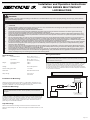
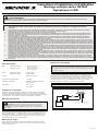
Wiring for single and dual color beacons are as shown in FIGURE 1. All wiring
should be a minimum of 20 AWG. The positive line must have a 3 amp fuse,
as shown. A switch may be used to control the on/o function. Route the
ground wire directly back to negative battery terminal. Pack dielectric grease,
such as Dow Corning 4, around each electric connection exposed to moisture
or the ambient environment.
Important! Disable power before wiring the beacon.
Position the beacon in the desired mounting location. Using the base ange as
a template, mark the mounting hole locations. Drill three 13/64” mounting holes.
Drill a hole for power wire routing as desired. The use of a grommet is recom-
mended for wires passing through compartment walls. Secure the beacon in
place using the included #10 hardware.
Permanent Mounting:
Caution: When drilling into any vehicle surface, make sure the area is free
from any electrical wires, fuel lines, vehicle upholstery, etc. that could be
damaged.
Pipe Mounting:
Remove the surface mount ange and four screws from the beacon’s base.
Route the wires through the 1/2” NPT thread pipe and thread the beacon on until
secured.
FIGURE 1
FUSE (3A)
(USER SUPPLIED)
SWITCH
(USER SUPPLIED)
RED
BLACK
BLUE - FLASH PATTERN SELECT
(MOMENTARY TO GROUND (-)),
DIM (TO POWER (+))
ISOLATE WHEN NOT IN USE
YELLOW - SYNC
(-)(+)
Installation and Operation Instructions
CB7265 SERIES MULTI MOUNT
LED BEACONS

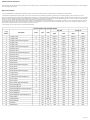
Flash Pattern Selection:
Flash patterns are selected by touching the blue wire to the black ground (-) wire for less than a second. Holding the blue and black wires for longer than a second toggles
to the preceding ash pattern.
Synchronization:
Syncing capabilities are available with compatible Code 3 products via the yellow wire with the ash patterns indicated in the charts below:
1. Determine the desired style of ash pattern for each unit and set each unit individually (without the yellow wires connected together) to avoid confusion. It is also
strongly recommended that the same style of ash pattern be used on all units to produce the most eective warning pattern. NOTE: Phases A and B for each style of ash
pattern in the table denote the relative timing between units connected in a synchronizing installation. To operate simultaneously, each unit must be set to the same phase
(A + A or B + B); to operate alternately, units must be set to have the opposite phase (A + B or B + A).
2. Connect the yellow sync wires together and check that the units are ashing in a synchronized manner as expected. If a pattern on one unit appears incorrect, the blue
pattern select wire can be used to cycle forward or backward on that individual unit until the correct pattern is selected. Note: This will only change the pattern in the one
unit and will not aect the other units connected to the yellow sync wire.
3. If the yellow wire is unused, leave unconnected and insulated.
Page 2 of 3

Page 3 of 3
Manufacturer Limited Warranty and Limitation of Liability:
Manufacturer warrants that on the date of purchase, this product will conform to Manufacturer’s specications for this product (which are available from the Manufacturer
upon request). This Limited Warranty extends for sixty (60) months from the date of purchase.
DAMAGE TO PARTS OR PRODUCTS RESULTING FROM TAMPERING, ACCIDENT, ABUSE, MISUSE, NEGLIGENCE, UNAPPROVED MODIFICATIONS, FIRE OR
OTHER HAZARD; IMPROPER INSTALLATION OR OPERATION; OR NOT BEING MAINTAINED IN ACCORDANCE WITH THE MAINTENANCE PROCEDURES SET
FORTH IN MANUFACTURER’S INSTALLATION AND OPERATING INSTRUCTIONS VOIDS THIS LIMITED WARRANTY.
Exclusion of Other Warranties:
MANUFACTURER MAKES NO OTHER WARRANTIES, EXPRESSED OR IMPLIED. THE IMPLIED WARRANTIES FOR MERCHANTABILITY, QUALITY OR FITNESS
FOR A PARTICULAR PURPOSE, OR ARISING FROM A COURSE OF DEALING, USAGE OR TRADE PRACTICE ARE HEREBY EXCLUDED AND SHALL NOT APPLY
TO THE PRODUCT AND ARE HEREBY DISCLAIMED, EXCEPT TO THE EXTENT PROHIBITED BY APPLICABLE LAW. ORAL STATEMENTS OR REPRESENTA-
TIONS ABOUT THE PRODUCT DO NOT CONSTITUTE WARRANTIES.
Remedies and Limitation of Liability:
MANUFACTURER’S SOLE LIABILITY AND BUYER’S EXCLUSIVE REMEDY IN CONTRACT, TORT (INCLUDING NEGLIGENCE), OR UNDER ANY OTHER THEORY
AGAINST MANUFACTURER REGARDING THE PRODUCT AND ITS USE SHALL BE, AT MANUFACTURER’S DISCRETION, THE REPLACEMENT OR REPAIR OF
THE PRODUCT, OR THE REFUND OF THE PURCHASE PRICE PAID BY BUYER FOR NON-CONFORMING PRODUCT. IN NO EVENT SHALL MANUFACTURER’S
LIABILITY ARISING OUT OF THIS LIMITED WARRANTY OR ANY OTHER CLAIM RELATED TO THE MANUFACTURER’S PRODUCTS EXCEED THE AMOUNT PAID
FOR THE PRODUCT BY BUYER AT THE TIME OF THE ORIGINAL PURCHASE. IN NO EVENT SHALL MANUFACTURER BE LIABLE FOR LOST PROFITS, THE
COST OF SUBSTITUTE EQUIPMENT OR LABOR, PROPERTY DAMAGE, OR OTHER SPECIAL, CONSEQUENTIAL, OR INCIDENTAL DAMAGES BASED UPON
ANY CLAIM FOR BREACH OF CONTRACT, IMPROPER INSTALLATION, NEGLIGENCE, OR OTHER CLAIM, EVEN IF MANUFACTURER OR A MANUFACTURER’S
REPRESENTATIVE HAS BEEN ADVISED OF THE POSSIBILITY OF SUCH DAMAGES. MANUFACTURER SHALL HAVE NO FURTHER OBLIGATION OR LIABILITY
WITH RESPECT TO THE PRODUCT OR ITS SALE, OPERATION AND USE, AND MANUFACTURER NEITHER ASSUMES NOR AUTHORIZES THE ASSUMPTION
OF ANY OTHER OBLIGATION OR LIABILITY IN CONNECTION WITH SUCH PRODUCT.
This Limited Warranty denes specic legal rights. You may have other legal rights which vary from jurisdiction to jurisdiction. Some jurisdictions do not allow the exclu-
sion or limitation of incidental or consequential damages.
920-0694-01 Rev. B
© 2018 Code 3, Inc.
all rights reserved.
10986 North Warson Road
St. Louis, MO 63114
Technical Service
(314) 996-2800
www.code3esg.com
An ECCO SAFETY GROUP™ Brand
www.eccosafetygroup.com

1. Para garantizar su propia seguridad y la de las personas a las que intenta proteger, es esencial una instalación correcta, combinada con la
formación del operador en el uso, cuidado y mantenimiento de los dispositivos de seguridad de emergencia.
2. Tenga cuidado cuando manipule conexiones eléctricas.
3. Este producto debe conectarse a tierra correctamente. Una conexión a tierra incorrecta o unas conexiones eléctricas cortocircuitadas pueden
provocar arcos de alta corriente, lo cual puede ocasionar lesiones personales o daños graves en el vehículo, incluso un incendio.
4. La correcta ubicación e instalación son vitales para el rendimiento de este dispositivo de seguridad. Instale este producto de forma que el
rendimiento de producción del sistema se maximice y los controles estén situados a una distancia apropiada para el operador, de modo que
pueda operar el sistema sin perder contacto visual con el camino.
5. No instale este producto ni tienda los cables en el área de despliegue de una bolsa de aire. Si se instala o monta equipo en esta área, se puede
reducir la ecacia de la bolsa de aire o convertirse en un proyectil que podría causar daños corporales o la muerte. Consulte el manual del
propietario del vehículo para ver el área de despliegue de la bolsa de aire. Es responsabilidad del operador/usuario determinar la ubicación
idónea para el montaje que garantice la seguridad de todos los pasajeros en el interior del vehículo. En particular, se deben evitar las áreas de
posible impacto con la cabeza.
6. No instale este producto ni coloque los cables en la zona de despliegue de un airbag. Si el equipo se monta o coloca en la zona de despliegue
de un airbag, el airbag perderá ecacia o el equipo puede salir despedido, lo cual puede causar lesiones graves o incluso mortales. Consulte el
manual del propietario del vehículo para conocer la zona de despliegue de los airbags. El usuario u operador son responsables de determinar
una posición de montaje adecuada que garantice la seguridad de todos los ocupantes del vehículo, y deben evitar zonas que puedan provocar
golpes en la cabeza.
7. El uso de este o cualquier otro dispositivo de seguridad no garantiza que todos los conductores puedan observar o reaccionar ante una señal
de advertencia ni que lo harán. Nunca tome el derecho de paso por sentado. Es su responsabilidad asegurarse de que puede continuar de
forma segura antes de entrar en una intersección, conducir contra el tráco, responder a una tasa alta de velocidad, o caminar sobre los carriles
de tráco o alrededor de estos.
8. Este equipo está diseñado para que solamente el personal autorizado pueda utilizarlo. El usuario es responsable de entender y obedecer todas
las leyes relacionadas con los dispositivos de señal de advertencia. Por lo tanto, el usuario debe comprobar todas las leyes y regulaciones de la
ciudad, el estado y el país. El fabricante no asume ninguna responsabilidad por cualquier pérdida ocasionada por el uso de este dispositivo de
seguridad.
No instale ni use este producto de seguridad si no ha leído y comprendido la información sobre seguridad que se incluye.
¡ADVERTENCIA!
Si no sigue las instrucciones del fabricante a la hora de instalar o usar el producto, pueden producirse daños materiales, y lesiones graves o incluso
mortales a aquellos que pretende proteger.
!
Página 1 de 2
Especicaciones:
Tamaño: Montaje permanente Ancho: 5” de diámetro x 3” de altura
Montaje en techo Ancho: 3,2” de diámetro x 2,5” de altura
Peso: Montaje permanente 0,94 lb.
Montaje en techo 0,84 lb
Voltaje: Consumo de corriente a 12,8 V CC
Consumo de corriente a 12,8 V CC: 1,7 A. máx.
Frecuencia de destellos: Consulte la tabla de patrones de destello
Rango de temperatura: -22°F a 122°F
-30°C a 50°C
Instalación y montaje:
Retire la baliza con cuidado y colóquela sobre una supercie plana. Examine
la unidad en busca de daños producidos por el transporte, lentes quebrados,
etc. Si se detecta algún daño, comuníquese con la empresa de transporte o el
distribuidor. No utilice piezas dañadas o rotas.
Instrucciones para el cableado:
El cableado para las balizas de uno y dos colores se muestra en la IMAGEN 1.
Todo el cableado debe ser de un mínimo de 20 AWG. La línea positiva debe
tener un fusible de 3 A, como se muestra en la imagen. Se puede usar un
interruptor para controlar la función de encendido/apagado. Tienda el cable de
tierra directamente de vuelta al terminal negativo de la batería. Empaque con
grasa dieléctrica, como Dow Corning 4, alrededor de cada conexión eléctrica
expuesta a la humedad o al ambient.
¡Importante! Desactive la alimentación antes de
conectar la baliza.
Coloque la baliza en el lugar de montaje deseado. Utilice la brida de la base
como ejemplo y marque las ubicaciones de los agujeros de montaje. Perfore tres
oricios de montaje de 13/64”. Perfore un oricio para realizar el tendido deseado
de las conexiones eléctricas. Se recomienda el uso de un pasacables para los
cables que pasan a través de las paredes del compartimiento. Fije la baliza en la
ubicación con la tornillería incluida n.° 10.
Montaje permanente:
Montaje en techo:
Retire la brida de montaje de la supercie y los cuatro tornillos de la base de la
baliza. Tienda los cables por el tubo roscado NPT de 1/2” y enrosque la baliza
hasta que se je.
FIGURA 1
¡Precaución! Cuando perfore cualquier supercie del
vehículo, asegúrese de que el área esté libre de cualquier
tipo de cables eléctricos, tuberías de combustible, tapicería de vehículos, etc.,
que pudieran resultar dañados.
!
¡Importante! Esta unidad es un dispositivo de seguridad y se debe
conectar a su propia fuente de poder de fusibles separada para
asegurar su funcionamiento continuo si cualquier otro accesorio eléctrico
falla..
FUSIBLE (3A)
(SUMINISTRADO POR EL USUARIO)
INTERRUPTOR
(SUMINISTRADO POR EL USUARIO)
ROJO
NEGRO
Azul: selección de patrón de destello (momentáneo en conexión a tierra
[-]), atenuación (a la alimentación [+]). Aíslelo cuando no se encuentre
en uso.
AMARILLO - SINC.
(-)(+)
Instrucciones de instalacion y operacion
Montaje múltiple de la serie CB7265
Balizas LED

Selección de patrones de destello:
Los patrones de destello se seleccionan tocando el cable azul al cable de tierra negro (-) durante menos de un segundo. Si sostiene los cables azul y negro durante más
de un segundo, se cambiará al patrón de destello anterior.
Sincronización:
Las capacidades de sincronización están disponibles con todos los productos compatibles de CODE 3 mediante el cable amarillo con los patrones de destello que se
indican en las siguientes tablas:
1. Determine el estilo del patrón de destello deseado para cada unidad y ajuste cada unidad de forma individual (sin los cables amarillos conectados entre sí) para evitar
confusiones. También se recomienda encarecidamente que se utilice el mismo estilo de patrón de destello en todas las unidades para producir el patrón de advertencia
más efectivo. NOTA: Las fases A y B para cada estilo de patrón de destello en la tabla indican la sincronización relativa entre las unidades conectadas en una
instalación en sincronización. Para hacerlas funcionar simultáneamente, cada unidad se debe ajustar a la misma fase
(A + A o B + B); para hacerlas funcionar de forma alternada, las unidades se deben ajustar para tener la fase opuesta (A + B o B + A).
2. Conecte los cables amarillos de sincronización entre sí y revise que las unidades estén destellando de manera sincronizada según lo previsto. Si el patrón de una
unidad parece incorrecto, el cable azul de selección del patrón se puede utilizar para cambiar el patrón hacia delante o hacia atrás en esa unidad en particular hasta que
se seleccione el patrón correcto. Nota: Esto solo cambiará el patrón en una unidad y no afectará a las otras unidades conectadas al cable amarillo de sincronización.
3. Si el cable amarillo no se utiliza, no lo conecte y aíslelo.
Limitación de responsabilidad y garantía limitada del fabricante:
El fabricante garantiza que al momento de la compra, este producto cumple con las especicaciones del fabricante para el mismo
(disponibles a pedido). El fabricante garantiza además que el presente producto está libre de defectos en sus materiales y en su
fabricación. Esta garantía limitada se extiende durante sesenta (60) meses a partir de la fecha de la compra. Pueden aplicarse otras
garantías. Para más información, comuníquese con el fabricante. El fabricante, a criterio propio, reparará o cambiará todo producto que
determine como defectuoso y que esté sujeto a la presente garantía limitada.
EL DAÑO A LAS PIEZAS O PRODUCTOS QUE RESULTE DE LA MANIPULACIÓN INDEBIDA, ACCIDENTES, ABUSO, USO
INDEBIDO, NEGLIGENCIA, MODIFICACIONES NO APROBADAS, INCENDIOS U OTROS PELIGROS, LA INSTALACIÓN O EL
USO INCORRECTOS O LA FALTA DE MANTENIMIENTO CONFORME A LOS PROCEDIMIENTOS DE MANTENIMIENTO QUE SE
ESTABLECEN EN LAS INSTRUCCIONES DE INSTALACIÓN Y USO DEL FABRICANTE, ANULA LA PRESENTE GARANTÍA LIMITADA.
LAS REPRESENTACIONES O DESCRIPCIONES ORALES DEL PRODUCTO QUE PUEDAN HABER SIDO REALIZADAS POR
VENDEDORES, DISTRIBUIDORES, AGENTES U OTROS REPRESENTANTES DEL FABRICANTE NO CONSTITUYEN GARANTÍAS.
ESTA GARANTÍA LIMITADA NO PODRÁ ENMENDARSE, MODIFICARSE NI AMPLIARSE EXCEPTO MEDIANTE UN ACUERDO
ESCRITO FIRMADO POR UN REPRESENTANTE AUTORIZADO DEL FABRICANTE QUE HAGA REFERENCIA EN FORMA EXPRESA
A ELLA.
Exclusión de otras garantías: EL FABRICANTE NO OTORGA NINGUNA OTRA GARANTÍA, EXPRESA O IMPLÍCITA.
MEDIANTE LA PRESENTE, SE EXCLUYEN LAS GARANTÍAS IMPLÍCITAS DE COMERCIABILIDAD O APTITUD PARA UN
PROPÓSITO EN PARTICULAR, QUE NO SE APLICARÁN AL PRODUCTO. EL ÚNICO Y EXCLUSIVO REMEDIO DEL COMPRADOR
CON RESPECTO AL CONTRATO, DERECHOS POR DAÑOS O CUALQUIER OTRA TEORÍA CONTRA EL FABRICANTE
RELACIONADA CON EL PRODUCTO Y SU USO SERÁ LA REPARACIÓN O EL REEMPLAZO DEL PRODUCTO SEGÚN SE DESCRIBE
ANTERIORMENTE.
Limitación de responsabilidad: EN EL CASO DE RESPONSABILIDAD POR DAÑOS QUE SURJAN DE LA PRESENTE
GARANTÍA LIMITADA O POR CUALQUIER OTRO RECLAMO RELACIONADO CON LOS PRODUCTOS DEL FABRICANTE,
CON LA RESPONSABILIDAD DEL FABRICANTE FRENTE A LOS DAÑOS, QUEDARÁ LIMITADA AL IMPORTE PAGADO POR EL
PRODUCTO EN EL MOMENTO DE LA COMPRA ORIGINAL. EL FABRICANTE NO SERÁ RESPONSABLE, BAJO NINGÚN MOTIVO,
POR EL LUCRO CESANTE, EL COSTO DE LA MANO DE OBRA NI DEL EQUIPO DE SUSTITUCIÓN, DAÑOS A LA PROPIEDAD
NI POR OTROS DAÑOS ESPECIALES, RESULTANTES O INDIRECTOS EN FUNCIÓN DE RECLAMOS POR INCUMPLIMIENTO
CONTRACTUAL, INSTALACIÓN INAPROPIADA, NEGLIGENCIA U OTROS, INCLUSO SI EL FABRICANTE O UNO DE SUS
REPRESENTANTES HUBIESE ANTICIPADO LA POSIBILIDAD DE DICHOS DAÑOS. EL FABRICANTE NO TENDRÁ NINGUNA OTRA
OBLIGACIÓN O RESPONSABILIDAD RESPECTO DEL PRODUCTO O SU VENTA, OPERACIÓN Y USO NI SUPONE O AUTORIZA
QUE SE SUPONGA TODA OTRA OBLIGACIÓN O RESPONSABILIDAD RELACIONADAS CON DICHO PRODUCTO.
Esta garantía limitada dene los derechos legales especícos. Es posible que tenga otros derechos legales que varían de estado a
estado. Algunos estados no permiten la exclusión o limitación de daños resultantes o indirectos.
Página 2 de 2920-0694-01 Rev. B
Instrucciones de instalacion y operacion
Montaje múltiple de la serie CB7265
Balizas LED
10986 North Warson Road
St. Louis, MO 63114
Servicio de atención al cliente
EE. UU.: (314) 996-2800
Reino Unido: +44 (0)113 237 5340Australia:
+61 (0)3 63322444
Una marca de ECCO SAFETY GROUP™Brand
www. code3esg.com
www.eccosafetygroup.com

1. Une installation correcte, associée à une formation de l’opérateur à l’utilisation, à l’entretien et à la maintenance des dispositifs de sécurité
d’urgence, est essentielle pour garantir votre sécurité et celle de ceux que vous souhaitez protéger.
2. Soyez prudent lorsque vous manipulez des connexions électriques sous tension.
3. Ce produit doit être correctement mis à la masse. Une mise à la masse inadéquate et/ou un court-circuit des connexions électriques peuvent
provoquer l’apparition d’un arc électrique haute tension susceptible de causer des blessures corporelles et/ou des dommages graves sur le
véhicule, y compris un incendie.
4. Une installation et un positionnement corrects sont essentiels au bon fonctionnement de ce dispositif de sécurité. Installez ce produit de
manière à optimiser les performances de sortie du système et de sorte que les commandes soient à portée de main de l’opérateur, an qu’il
puisse utiliser le système sans perdre le contact visuel avec la chaussée.
5. N’installez pas ce produit et n’acheminez pas de câbles dans la zone de déploiement d’un airbag. Tout équipement monté ou situé dans la zone
de déploiement d’un airbag est susceptible de réduire l’ecacité de cet airbag ou de devenir un projectile pouvant causer des blessures graves,
voire mortelles. Reportez-vous au manuel d’utilisation du véhicule pour en savoir davantage sur la zone de déploiement de l’airbag. Il incombe à
l’utilisateur/à l’opérateur de dénir un emplacement de montage approprié assurant la sécurité de tous les passagers à l’intérieur du véhicule, en
évitant en particulier les zones d’impact potentiel de la tête.
6. N’installez pas ce produit et n’acheminez pas de câbles dans la zone de déploiement d’un airbag. Tout équipement monté ou situé dans la zone
de déploiement d’un airbag est susceptible de réduire l’ecacité de cet airbag ou de devenir un projectile pouvant causer des blessures graves,
voire mortelles. Reportez-vous au manuel d’utilisation du véhicule pour en savoir davantage sur la zone de déploiement de l’airbag. Il incombe à
l’utilisateur/à l’opérateur de dénir un emplacement de montage approprié assurant la sécurité de tous les passagers à l’intérieur du véhicule, en
évitant en particulier les zones d’impact potentiel de la tête.
7. L’utilisation de ce dispositif de sécurité ou de tout autre dispositif de sécurité ne garantit pas que tous les conducteurs peuvent ou vont observer
ou réagir à un signal d’avertissement. Ne prenez jamais la priorité pour acquise. Il est de votre responsabilité de vous assurer que vous pouvez
vous déplacer en toute sécurité avant d’entrer dans une intersection, de conduire en sens inverse de la circulation, de réagir à une vitesse élevée
et de marcher sur ou autour des voies de circulation.
8. Cet équipement est destiné uniquement au personnel autorisé. Il incombe à l’utilisateur de comprendre et de respecter toutes les lois relatives
aux dispositifs de signalisation d’avertissement. Par conséquent, l’utilisateur doit s’informer sur toutes les lois et réglementations en vigueur
dans la ville, la région et le pays où il se trouve. Le fabricant décline toute responsabilité en cas de perte découlant de l’utilisation de ce dispositif
de sécurité.
N’installez pas et/ou n’utilisez pas ce produit de sécurité avant d’avoir lu et compris les consignes de sécurité
fournies.
!
AVERTISSEMENT!
Une installation ou une utilisation non conforme aux recommandations du fabricant peut entraîner des dommages matériels et des blessures
graves, voire mortelles pour les personnes que vous cherchez à protéger!
Important! Cette unité est un dispositif de sécurité et elle doit être
connectée à son propre point d’alimentation indépendant protégé par fusible
pour garantir son fonctionnement continu en cas de défaillance d’un autre
accessoire électrique.
Instructions de câblage :
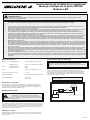
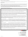
Le câblage des gyrophares unicolores et bicolores est illustré sur la FIGURE
1. Tous les câbles doivent avoir un diamètre d’au moins 20 AWG. La ligne
positive doit avoir un fusible de 3 A, comme illustré. Un commutateur peut
être utilisé pour commander la fonction marche/arrêt. Acheminer le câble de
masse directement vers la borne négative de la batterie. Placer de la graisse
diélectrique (Dow Corning 4, par exemple) autour de chaque connexion
électrique exposée à l’humidité ou à l’environnement ambiant.
Important ! Désactiver l’alimentation avant de câbler le gyrophare.
Caractéristiques :
Taille : Montage permanent l : dia. 127,0 mm (5,0”) x
H 76,2 mm (3,0”)
Montage sur tuyau l : dia. 127,0 mm (3,2”) x
H 76,2 mm (2,5”)
Poids : Montage permanent 0,43 kg (0.94 lb.)
Montage sur tuyau 0,38 kg (0.84 lb.)
Tension : Systèmes 12-24 VCC
Appel de courant @ 12,8 VCC : 1,7 A. Max
Vitesse de clignotement : Consulter les tableaux des motifs
de clignotement
Temp. Plage : -22°F à 122°F
-30°C à 50°C
Installation et montage :
Enlevez le phare soigneusement et mettez-le sur une surface plane. Examinez
l'unité pour déceler les dommages survenus en cours de transport, les objectifs
cassés, etc. Si des dommages sont constatés, contactez la compagnie de transport
ou le distributeur. Ne pas utiliser des pièces endommagées ou cassées.
Montage permanent :
Attention! Lorsque vous percez un trou dans une surface de
véhicule, assurez-vous que cette zone est exempte de ls électriques,
de canalisations d’essence, de garniture souple, etc. qui pourraient être
endommagés.
!
Positionnez le phare à l’endroit de montage souhaité. En utilisant la bride de base
comme gabarit, marquez les emplacements des trous de montage. Percez trois
trous de montage de 5 mm (13/64"). Percez un trou pour l'acheminement du l
d'alimentation au besoin. L'utilisation d'un passe-l est recommandée pour les
ls passant à travers les parois des compartiments. Fixez le phare en place en
utilisant le matériel no. 10 fourni par le client.
Montage sur tuyau :
Retirez la bride de montage en surface et les quatre vis de la base du phare.
Faites passer les ls à travers le tuyau de 1/2 po NPT et vissez le phare jusqu'à
ce qu'il soit xé en place.
FUSIBLE (3A)
(FOURNI PAR L’UTILISATEUR)
COMMUTATEUR
(FOURNI PAR L’UTILISATEUR)
ROUGE
NOIR
Bleu - sélection du modèle de clignotement (momentané à la masse (-)),
faible (à l'alimentation (+)). Isoler lorsqu'il n'est pas utilisé
JAUNE - SYNCH
(-)(+)
FIGURE 1
Page 1 sur 2
Instructions d’installations et d’utilisation
Montage multiple séries CB7265
Gyrophares à LED

Sélection du modèle de clignotement :
Les modèles de clignotement sont sélectionnés en mettant en contact le l bleu et le l noir de masse (-) pendant moins d’une seconde. Maintenir en contact les ls bleu
et noir pendant plus d’une seconde permet de passer au modèle de clignotement précédent.
Synchronisation :
Les fonctions de synchronisation sont disponibles avec tous les produits CODE 3 compatibles via le l jaune, avec les modèles de clignotement indiqués dans les tableaux
ci-dessous :
1. Déterminer le modèle de clignotement souhaité pour chaque unité et régler chaque unité individuellement (sans que les ls jaunes ne soient connectés) pour éviter
toute confusion. Il est également fortement recommandé d’utiliser le même modèle de clignotement sur toutes les unités pour produire un modèle d’avertissement le plus
ecace possible. REMARQUE : les phases A et B pour chaque modèle de clignotement dans le tableau indiquent la synchronisation relative entre les unités connectées
dans une installation de synchronisation. Pour fonctionner simultanément, chaque unité doit être réglée sur la même phase
(A + A ou B + B) ; pour fonctionner en alternance, les unités doivent être réglées sur des phases opposées (A + B ou B + A).
2. Connecter les ls de synchronisation jaunes et vérier que les unités clignotent de manière synchronisée comme souhaité. Si le modèle d’une unité semble incorrect,
le l bleu de sélection de modèle de cette unité peut être utilisé pour faire déler les modèles vers l’avant ou vers l’arrière jusqu’à ce que le bon modèle soit sélectionné.
Remarque : cette opération modie le modèle d’une seule unité et n’aecte pas les autres unités connectées au l de synchronisation jaune.
3. Si le l jaune n’est pas utilisé, ne pas le brancher et l’isoler.
Garantie limitée et limitation de responsabilité du fabricant :
Le fabricant garantit qu’à la date d’achat ce produit sera conforme aux caractéristiques techniques dénies par ses soins (disponibles sur
demande) et qu’il est exempt de vices de fabrication et de main-d’œuvre. La présente garantie limitée est valable soixante (60) mois à
compter de la date d’achat. D’autres garanties peuvent s’appliquer. Pour plus d’informations, contactez le fabricant. Le fabricant réparera
ou remplacera, à son entière discrétion, tout produit qu’il jugera défectueux, sous réserve de la présente garantie limitée.
LA PRÉSENTE GARANTIE LIMITÉE EST NULLE ET NON AVENUE EN CAS D’ENDOMMAGEMENT DE PIÈCES OU DE PRODUITS
RÉSULTANT D’UNE ALTÉRATION, D’UN ACCIDENT, D’UN ABUS, D’UNE MAUVAISE UTILISATION, D’UNE NÉGLIGENCE, DE
MODIFICATIONS NON AUTORISÉES, D’UN INCENDIE OU D’UN AUTRE DANGER; D’UNE MAUVAISE INSTALLATION OU D’UN
FONCTIONNEMENT INCORRECT; OU ENCORE D’UN ENTRETIEN NON CONFORME AUX PROCÉDURES D’ENTRETIEN DÉFINIES
DANS LES INSTRUCTIONS D’INSTALLATION ET D’UTILISATION DU FABRICANT.
LES DÉCLARATIONS OU OBSERVATIONS ORALES AU SUJET DU PRODUIT QUI POURRAIENT AVOIR ÉTÉ FAITES PAR DES
VENDEURS, DES REVENDEURS, DES AGENTS OU D’AUTRES REPRÉSENTANTS DU FABRICANT NE CONSTITUENT PAS DES
GARANTIES. LA PRÉSENTE GARANTIE LIMITÉE NE PEUT ÊTRE MODIFIÉE ET SON CHAMP D’APPLICATION NE PEUT ÊTRE
ÉLARGI EXCEPTÉ EN VERTU D’UN ACCORD ÉCRIT SIGNÉ PAR UN REPRÉSENTANT AUTORISÉ DU FABRICANT QUI FAIT
EXPRESSÉMENT RÉFÉRENCE À LA PRÉSENTE GARANTIE.
Exclusion d’autres garanties : LE FABRICANT N’ACCORDE AUCUNE AUTRE GARANTIE, EXPRESSE OU TACITE. LES
GARANTIES IMPLICITES DE QUALITÉ MARCHANDE OU D’APTITUDE À UN USAGE PARTICULIER SONT EXCLUES ET NE
S’APPLIQUERONT PAS AU PRODUIT. LE SEUL ET UNIQUE RECOURS DE L’ACHETEUR CONTRE LE FABRICANT CONCERNANT
LE PRODUIT ET SON UTILISATION, QUEL QUE SOIT LE FONDEMENT DE RESPONSABILITÉ INVOQUÉ (RESPONSABILITÉ
CONTRACTUELLE, DÉLICTUELLE OU AUTRE), SERA LE REMPLACEMENT OU LA RÉPARATION DU PRODUIT COMME INDIQUÉ
CI-DESSUS.
Limitation de responsabilité : EN CAS DE RESPONSABILITÉ POUR DES DOMMAGES DÉCOULANT DE LA PRÉSENTE
GARANTIE LIMITÉE OU TOUTE AUTRE RÉCLAMATION RELATIVE AUX PRODUITS DU FABRICANT, LA RESPONSABILITÉ DU
FABRICANT SE LIMITERA AU MONTANT PAYÉ POUR LE PRODUIT LORS DE L’ACHAT INITIAL. LE FABRICANT NE SERA EN
AUCUN CAS RESPONSABLE DU MANQUE À GAGNER, DU COÛT DE L’ÉQUIPEMENT DE SUBSTITUTION OU DE LA MAIN-
D’ŒUVRE, DES DOMMAGES MATÉRIELS OU D’AUTRES DOMMAGES PARTICULIERS, INDIRECTS OU ACCESSOIRES FONDÉS
SUR UNE RÉCLAMATION POUR RUPTURE DE CONTRAT, MAUVAISE INSTALLATION, NÉGLIGENCE OU TOUTE AUTRE
RÉCLAMATION, MÊME SI LE FABRICANT OU L’UN DE SES REPRÉSENTANTS A ÉTÉ INFORMÉ DE L’ÉVENTUALITÉ DE TELS
DOMMAGES. LE FABRICANT NE S’ACQUITTERA D’AUCUNE AUTRE OBLIGATION OU RESPONSABILITÉ QUANT AU PRODUIT
OU SA VENTE, SON FONCTIONNEMENT ET SON UTILISATION, ET N’ADMET NI N’AUTORISE L’HYPOTHÈSE DE TOUTE AUTRE
OBLIGATION OU RESPONSABILITÉ EN RELATION AVEC CE PRODUIT.
La présente garantie limitée vous accorde des droits juridiques spéciques. Vous pouvez également jouir d’autres droits, lesquels
peuvent varier d’un état à l’autre. Certains États n’autorisent pas l’exclusion ou la limitation de dommages indirects ou accessoires.
Page 2 sur 2920-0694-01 Rev. B
Instructions d’installations et d’utilisation
Montage multiple séries CB7265
Gyrophares à LED
10986 North Warson Road
St. Louis, MO 63114
Service client
États-Unis(314) 996-2800
Royaume-Uni +44 (0)113 237 5340
AUS +61 (0)3 63322444
www.code3esg.com
www.eccosafetygroup.com
Une marque ECCO SAFETY GROUP™

Seite 1 von 2
1. Eine ordnungsgemäße Installation sowie eine Bedienerschulung in Hinsicht auf die Verwendung, Pege und Wartung von Sicherheitsvor-
richtungen sind unerlässlich, um Ihre Sicherheit und die Sicherheit der Personen, denen Sie helfen möchten, zu gewährleisten.
2. Gehen Sie bei der Arbeit mit stromführenden elektrischen Anschlüssen vorsichtig vor.
3. Dieses Produkt muss ordnungsgemäß geerdet werden. Eine unzureichende Erdung und/oder ein Kurzschluss der elektrischen Anschlüsse
können zu Hochstromlichtbögen führen, die Verletzungen und/oder schwere Schäden am Fahrzeug, einschließlich Fahrzeugbrand, verursa-
chen können.
4. Die richtige Platzierung und Installation sind für die Leistung der Sicherheitsvorrichtung von entscheidender Bedeutung. Installieren Sie die-
ses Produkt so, dass die Ausgangsleistung des Systems maximiert wird und die Bedienelemente sich in Reichweite des Bedieners benden
damit er/sie das System bedienen kann, ohne den Blick von der Fahrbahn nehmen zu müssen.
5. Montieren Sie dieses Produkt nicht im Entfaltungsbereich eines Airbags und verlegen Sie dort auch keine Kabel. Geräte, die im Entfaltungs-
bereich eines Airbags montiert oder platziert werden, beeinträchtigen möglicherweise die Wirksamkeit des Airbags oder können zu „Ge-
schossen“ werden, die schwere Verletzungen oder den Tod verursachen können. Informationen zum Entfaltungsbereich des Airbags nden
Sie im Fahrerhandbuch des Fahrzeugs. Es liegt in der Verantwortung des Benutzers/Bedieners, einen geeigneten Montageort festzulegen,
um die Sicherheit aller Fahrzeuginsassen zu gewährleisten und insbesondere Bereiche zu vermeiden, in denen möglicherweise Kopfverlet-
zungen auftreten können.
6. Es liegt in der Verantwortung des Fahrers sicherzustellen, dass während der Verwendung alle Funktionen dieses Produkts ordnungsgemäß
funktionieren. Der Fahrer muss während der Verwendung sicherstellen, dass das Warnsignal nicht durch Fahrzeugkomponenten (z. B. oene
Koerraumklappe oder Türen), Personen, Fahrzeuge oder andere Hindernisse blockiert wird.
7. Durch die Verwendung dieser oder anderer Sicherheitsvorrichtungen kann nicht gewährleistet werden, dass alle Verkehrsteilnehmer das
Warnsignal sehen oder darauf reagieren. Sehen Sie das Vorfahrtsrecht niemals als selbstverständlich an. Es liegt in Ihrer Verantwortung
sicherzustellen, dass keine Gefahr für Sie besteht, bevor Sie eine Kreuzung überqueren, entgegen der Verkehrsrichtung oder mit hoher
Geschwindigkeit fahren oder sich außerhalb des Fahrzeugs auf oder in der Nähe der Fahrspur bewegen.
8. Dieses Gerät darf nur von autorisiertem Personal verwendet werden. Der Benutzer ist dafür verantwortlich, alle Gesetze in Bezug auf Warn-
systeme zu verstehen und einzuhalten. Daher sollte der Benutzer alle geltenden Gesetzte und Vorschriften auf Stadt-, Landes- und Bundese-
bene prüfen. Der Hersteller übernimmt keine Haftung für Verluste, die durch die Verwendung dieser Sicherheitsvorrichtung entstehen.
nstallieren und/oder verwenden Sie dieses Sicherheitsprodukt nur, wenn Sie die Sicherheitsinformationen in dieser
Anleitung gelesen und verstanden haben.
Wenn Sie dieses Produkt nicht gemäß den Empfehlungen des Herstellers installieren oder verwenden, kann dies zu Sachschäden, schweren
Personenschäden und/oder zum Tod für Sie und die Personen, denen Sie helfen möchten, führen!
!
WARNUNG!
Spezikationen:
Größe: Permanente Befestigung B: 127,0 mm (5,0”) Durchm.
x 76,2 mm (3,0”) H
Rohrhalterung B: 81,3 mm (3,2”) Durchm. x
63,5 mm (2,5”) H
Gewicht: Permanente Befestigung 0,43 kg (0,94 lb.)
Rohrhalterung 0,38 kg (0,84 lb.)
Spannung: 12–24 VDC-Systeme
Stromaufnahme bei 12,8 VDC: 1,7 A Max.
Blinktakt: Siehe Tabelle mit Leuchtmuster
Temperatur- bereich: -22° bis 122°F
-30° bis 50°C
Installation und Montage:
Nehmen Sie die Leuchte vorsichtig aus der Verpackung und legen Sie sie auf
eine ebene Fläche. Untersuchen Sie das Gerät auf Transportschäden,
beschädigte Linsen usw. Wenden Sie sich bei Schäden an das
Transportunternehmen oder den Händler. Verwenden Sie keine beschädigten
Teile.
Anweisungen zur Verkabelung:
Wichtig! Dieses Gerät ist eine Sicherheitsvorrichtung und muss an eine
separate, abgesicherte Stromversorgung angeschlossen werden, um
den weiteren Betrieb bei Ausfall eines anderen elektrischen Zubehörs zu
gewährleisten.
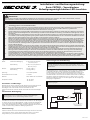
Die Verkabelung für ein- und zweifarbige Leuchten erfolgt wie in ABBILDUNG
1 dargestellt. Alle Kabel sollten mindestens über 20 AWG verfügen. Die
positive Leitung muss wie in der Abbildung dargestellt über eine Sicherung
von 3 A verfügen. Zum Steuern der Ein-/Aus-Funktion kann ein Schalter
verwendet werden. Führen Sie den Schutzleiter direkt zurück zum Minuspol
der Batterie.Tragen Sie dielektrisches Fett, z. B. Dow Corning 4, um jede
elektrische Verbindung herum auf, die Feuchtigkeit oder den Umgebungs-
bedingungen ausgesetzt ist.
Important! Schalten Sie vor der Verkabelung der Leuchte die
Stromversorgung ab.
Positionieren Sie die Leuchte am gewünschten Montageort. Verwenden Sie den
Sockelansch als Schablone und markieren Sie die Positionen der Montagelöch-
er. Bohren Sie drei 5,2-mm-Montagelöcher (13/64”). Bohren Sie bei Bedarf ein
Loch für die Verlegung des Stromkabels. Für Kabel, die durch Trennwände
führen, wird die Verwendung einer Tülle empfohlen. Befestigen Sie die Leuchte
mit den im Lieferumfang enthaltenen Befestigungsteilen #10.
Permanente Befestigung:
Achtung: Achten Sie beim Bohren in eine Fahrzeugoberäche darauf,
dass der Bereich frei von elektrischen Leitungen, Kraftstoeitungen,
Fahrzeugpolstern usw. ist, die beschädigt werden könnten.
Rohrhalterung:
Entfernen Sie den Flansch für die Oberächenmontage und die vier Schrauben
vom Sockel der Leuchte. Führen Sie die Kabel durch das 12,7-mm-NPT-
Rohrgewinde (1/2”) und drehen Sie die Leuchte ein, bis sie fest ist.
FIGURA 1
FUSE (3A)
(USER SUPPLIED)
SWITCH
(USER SUPPLIED)
RED
BLACK
BLUE - FLASH PATTERN SELECT
(MOMENTARY TO GROUND (-)),
DIM (TO POWER (+))
ISOLATE WHEN NOT IN USE
YELLOW - SYNC
(-)(+)
Installations- und Bedienungsanleitung:
Serie CB7265 – Verschiedene
Befestigungsmöglichkeiten LED-Leuchten

Installations- und Bedienungsanleitung:
Serie CB7265 – Verschiedene
Befestigungsmöglichkeiten LED-Leuchten
Auswahl des Leuchtmusters:
Die Leuchtmuster werden ausgewählt, indem das blaue Kabel für weniger als eine Sekunde mit dem schwarzen Massekabel (-) verbunden wird. Werden das blaue und
schwarze Kabel für länger als eine Sekunde verbunden, wird auf das vorhergehende Leuchtmuster umgeschaltet.
Synchronisierung:
Synchronisierungsfunktionen stehen über das gelbe Kabel mit allen kompatiblen CODE 3 -Produkten zur Verfügung, wobei die Leuchtmuster in den folgenden Tabellen
angegeben sind:
1. Legen Sie das gewünschte Leuchtmuster für jedes Gerät fest und stellen Sie jedes Gerät einzeln ein (ohne die gelben Kabel miteinander zu verbinden), um
Verwechslungen zu vermeiden. Es wird außerdem dringend empfohlen, für alle Geräte dasselbe Leuchtmuster zu verwenden, um ein eektives Warnmuster zu
erzeugen. HINWEIS: Die Phasen A und B für alle Leuchtmuster in der Tabelle bezeichnen die Zeitdierenz zwischen den in einer Synchronisierungsinstallation
verbunden Einheiten. Für den gleichzeitigen Betrieb muss jede Einheit auf die gleiche Phase eingestellt werden
(A + A oder B + B). Für den abwechselnden Betrieb müssen die Einheiten so eingestellt werden, dass sie die entgegengesetzte Phase haben (A + B oder B + A).
2. Verbinden Sie die gelben Synchronisierungskabel miteinander und prüfen Sie, ob die Einheiten wie erwartet synchron blinken. Wenn eine Einheit ein falsches Muster
ausgibt, kann mit dem blauen Kabel zur Auswahl des Leuchtmusters auf dieser einzelnen Einheit vor- oder zurückgeschaltet werden, bis das richtige Muster ausgewählt
ist. Hinweis: Dadurch wird nur das Muster in dieser Einheit geändert. Einheiten, die mit dem gelben Synchronisierungskabel verbunden sind, werden nicht beeinusst.
3. Wenn das gelbe Kabel nicht verwendet wird, schließen Sie es nicht an und isolieren Sie es.
Code 3 (Hersteller)
Code 3 garantiert, dass dieses Produkt zum Zeitpunkt des Erwerbs den Spezikationen von CODE 3 für dieses Produkt (auf Anfrage bei
CODE 3 erhältlich) entspricht. Diese beschränkte Garantie gilt sechzig (60) Monate ab dem Zeitpunkt des Erwerbs.
BEI SCHÄDEN AN TEILEN ODER PRODUKTEN, DIE DURCH MANIPULATION, UNFALL, MISSBRAUCH, UNSACHGEMÄSSE VER-
WENDUNG, FAHRLÄSSIGKEIT, NICHT GENEHMIGTE VERÄNDERUNGEN, FEUER ODER SONSTIGE GEFAHR; UNSACHGEMÄSSE
INSTALLATION ODER BEDIENUNG; ODER NICHTEINHALTUNG DER IN DEN VON CODE 3 FESTGELEGTEN INSTALLATIONS- UND
BEDIENUNGSANWEISUNGEN FESTGELEGTEN WARTUNGSVERFAHREN IST DIESE BESCHRÄNKTE GARANTIE UNGÜLTIG.
Ausschluss sonstiger Garantieansprüche:
CODE 3 ÜBERNIMMT KEINE DARÜBER HINAUSGEHENDEN GARANTIEN, WEDER AUSDRÜCKLICH NOCH STILLSCHWEIGEND.
DIE STILLSCHWEIGENDEN GARANTIEN FÜR MARKTGÄNGIGKEIT, QUALITÄT ODER EIGNUNG FÜR EINEN BESTIMMTEN ZWECK;
ODER DIE SICH AUS DEM REGELMÄSSIGEN GESCHÄFTSGANG, DER NUTZUNG ODER DES HANDELSBRAUCHS ERGEBEN;
WERDEN HIERMIT AUSGESCHLOSSEN UND GELTEN NICHT FÜR DAS PRODUKT, SOWEIT NACH ANWENDBAREM RECHT ZULÄS-
SIG. MÜNDLICHE AUSSAGEN ODER ZUSICHERUNGEN ZUM PRODUKT STELLEN KEINE GARANTIEN DAR.
Rechtsbehelfe und Haftungsbeschränkung:
DIE ALLEINIGE HAFTUNG VON CODE 3 UND DER AUSSCHLIESSLICHE RECHTSBEHELF DES KÄUFERS, OB AUF VERTRAGLICHER
GRUNDLAGE, AUS UNERLAUBTER HANDLUNG (EINSCHLIESSLICH FAHRLÄSSIGKEIT) ODER EINEM SONSTIGEN RECHTLICHEN
GRUND GEGEN CODE 3 IN HINSICHT AUF DAS PRODUKT UND SEINE VERWENDUNG BESTEHEN NACH ERMESSEN VON CODE
3 IM ERSATZ ODER IN DER REPARATUR DES PRODUKTES ODER IN DER RÜCKERSTATTUNG DES KAUFPREISES, DEN DER
KÄUFER FÜR DAS NICHT KONFORME PRODUKT BEZAHLT HAT. UNTER KEINEN UMSTÄNDEN ÜBERSTEIGT DIE AUS DIESER BE-
SCHRÄNKTEN GARANTIE ODER EINEM ANDEREN ANSPRUCH IM ZUSAMMENHANG MIT DEN PRODUKTEN VON CODE 3 ENTSTE-
HENDE HAFTUNG VON CODE 3 DEN KAUFPREIS DES PRODUKTES ZUM ZEITPUNKT DES URSPRÜNGLICHEN ERWERBS DURCH
DEN KÄUFER. UNTER KEINEN UMSTÄNDEN HAFTET CODE 3 FÜR ENTGANGENE GEWINNE, KOSTEN FÜR ERSATZGERÄTE ODER
ARBEITSAUFWAND, SACHSCHADEN, ODER SONSTIGE SPEZIELLE SCHÄDEN, FOLGESCHÄDEN ODER BEILÄUFIGE SCHÄDEN
BASIEREND AUF ANSPRÜCHEN AUFGRUND VON VERTRAGSVERLETZUNG, FEHLERHAFTER INSTALLATION, FAHRLÄSSIGKEIT,
ODER ANDEREN ANSPRÜCHEN, SELBST WENN CODE 3 ODER EIN VERTRETER VON CODE 3 AUF DIE MÖGLICHKEIT SOLCHER
SCHÄDEN HINGEWIESEN WURDE. CODE 3 ÜBERNIMMT KEINE WEITERE VERPFLICHTUNG ODER HAFTUNG HINSICHTLICH DES
PRODUKTES ODER SEINES VERKAUFS, SEINER BEDIENUNG UND SEINER VERWENDUNG, UND CODE 3 ÜBERNIMMT KEINE
HAFTUNG UND GENEHMIGT KEINE ÜBERNAHME ANDERER VERPFLICHTUNGEN ODER HAFTUNGEN IM ZUSAMMENHANG MIT
DIESEM PRODUKT.
Diese beschränkte Garantie deniert bestimmte Rechte. Möglicherweise haben Sie andere Rechte, die je nach Rechtsprechung
variieren.
In einigen Rechtsprechungen ist der Ausschluss oder die Beschränkung von Neben- oder Folgeschäden nicht zulässig.
920-0694-01 Rev. B
10986 North Warson Road
St. Louis, MO 63114
Kundendienst
USA 001-800-635-5900
UK +44(0)113 237 5340
AUS +61(0)3 63322444
www.code3esg.com
Seite 2 von 2
-
 1
1
-
 2
2
-
 3
3
-
 4
4
-
 5
5
-
 6
6
-
 7
7
-
 8
8
-
 9
9


Code 3 CB7265 Series Installation And Operation Instructions Manual
- Typ
- Installation And Operation Instructions Manual
- Dieses Handbuch eignet sich auch für
in anderen Sprachen
- English: Code 3 CB7265 Series
- français: Code 3 CB7265 Series
- español: Code 3 CB7265 Series


