Yamaha CC-75 Benutzerhandbuch
- Kategorie
- Soundbar-Lautsprecher
- Typ
- Benutzerhandbuch

Active Servo
Technology
CC-75
Natural Sound Mini Component System
Chaîne Mini de la série “Natural Sound”
Natural Sound Mini Komponenten-System
Natural Sound Mini Komponent System
Sistema di Componenti Mini a Suono Naturale
Sistema de Componentes con Sonido Natural
Natural Sound Mini Component Systeem
OWNER‘S MANUAL
MODE D‘EMPLOI
BEDIENUNGSANLEITUNG
BRUKSANVISNING
MANUALE DI ISTRUZIONI
MANUAL DE INSTRUCCIONES
GEBRUIKSAANWIJZING
CC-75: RX-S75 + CDC-S75 + KXW-S75 + NX-S75

●
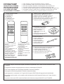
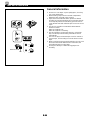
Remote control transmitter
●
Télécommande
●
Fernbedienung
●
Fjärrkontroll
●
Telecomando
●
Controlador remoto
●
Afstandbediening
●
Batteries (size AA, UM/SUM-3, R6, HP-7)
●
Piles (format AA, UM/SUM-3, R6, HP-7)
●
Batterien (Größe AA, UM/SUM-3, R6, HP-7)
●
Batterier (Storl. AA, UM/SUM-3, R6, HP-7)
●
Batterie (dimensioni AA, o UM/SUM-3, o R6, o HP-7)
●
Pilas (tamaño AA, tipo UM/SUM-3, R6, HP-7)
●
Batterijen (maat AA, UM/SUM-3, R6, HP-7)
●
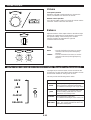
AM (MW/LW) loop antenna
●
Cadre-antenne AM (PO/GO)
●
MW/LW-Rahmenantenne
●
MV/LV ramantenn
●
Antenna ad anello per AM
(MW e LW)
●
Antena de cuadro AM (OM/OL)
●
AM (MW/LW) lusantenne
●
Indoor FM antenna
●
Antenne intérieure FM
●
UKW-Innenantenne
●
FM inomhusantenn
●
Antenna FM per interni
●
Antena interior de FM
●
FM binnenantenne
●
Speaker cords (for NX-S75)
●
Câbles d’enceintes (pour les enceintes NX-S75)
●
Lautsprecheranschlußkabel (für NX-S75)
●
Högtalarledningar (för NX-S75)
●
Cavi per gli altoparlanti (per l’NX-S75)
●
Cables de los altavoces (para el NX-S75)
●
Luidsprekerdraden (voor NX-S75)
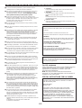
SUPPLIED ACCESSORIES
●
After unpacking, check that the following parts are contained.
ACCESSOIRES FOURNIS
●
Après le déballage, vérifier que les pièces suivantes sont incluses.
MITGELIEFERTES ZUBEHÖR
●
Nach dem Auspacken überprüfen, ob die folgenden Teile vorhanden sind.
MEDFÖLJANDE TILLBEHÖR
●
Kontrollera efter det apparaten packats upp att följande delar finns med.
ACCESSORI IN DOTAZIONE
●
Verificare che tutte le parti seguenti siano contenute nell’imballaggio dell’apparecchio.
ACCESORIOS INCLUIDOS
●
Desembale el aparato y verificar que los siguientes accesorios están en la caja.
BIJGELEVERDE ACCESSOIRES
●
Controleer na het uitpakken of de volgende onderdelen voorhanden zijn.
This product complies with the radio frequency interference requirements of the Council Directive 82/499/EEC and/or
87/308/EEC.
Cet appareil est conforme aux prescriptions de la directive communautaire 87/308/CEE.
Diese Geräte entsprechen der EG-Richtlinie 82/499/EWG und/oder 87/308/EWG.
Dette apparat overholder det gaeldende EF-direktiv vedrørende radiostøj.
Questo apparecchio è conforme al D.M.13 aprile 1989 (Direttiva CEE/87/308) sulla soppressione dei radiodisturbi.
Este producto está de acuerdo con los requisitos sobre interferencias de radio frequencia fijados por el Consejo Directivo
87/308 CEE.
Dit product voldoet aan de EEG normen betreffende radio-frekwentie storingen 82/499/EEG en/of 87/308/EEG.
<Except U.K. and Europe
Models>
<Excepté le modèles pour
le Royaume-Uni et
l’Europe>
<Außer Großbritannien- und
Europa-Modelle>
<Undantaget modell för
Storbritannien och Europa>
<Eccetto modelli per Gran
Bretagna e l’Europa>
<Excepto modelos para
Reino Unido y Europa>
<Behalve de modellen voor
Groot-Brittannië en Europa>
<U.K. and Europe models>
<Modèles pour le Royaume-
Uni et l’Europe>
<Großbritannien- und
Europa-Modelle>
<Modell för Storbritannien
och Europa>
<Modelli per Gran Bretagna
e l’Europa>
<Modelos para Reino Unido
y Europa>
<Modellen voor Groot-
Brittannië en Europa>

33
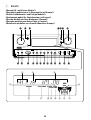
1 CDC-S75
CD CHANGER
CDC–S75
12 3
TIME EDIT REPEAT RANDOM SKIP
SEARCH
PLAY CHANGE OPEN/CLOSE
TIME
SINGLE
SINGLE REMAIN
TOTAL
TOTAL REMAIN
TOTAL
REMAIN
S F REPEAT PROGRAM RANDOM
EDIT
AB
2345 678910
11 12 13 14 15 16 17 18 19
1
20
OVER
12
5
67 8
3
9
4
0
A
1
9
2
3
4567 8
0
A

44
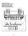
2 RX-S75
<Except U.K. and Europe Models>
<Excepté le modèles pour le Royaume-Uni et l’Europe>
<Außer Großbritannien- und Europa-Modelle>
<Undantaget modell för Storbritannien och Europa>
<Eccetto modelli per Gran Bretagna e l’Europa>
<Excepto modelos para Reino Unido y Europa>
<Behalve de modellen voor Groot-Brittannië en Europa>
DSS
ON/OFF
MODE
VOLUME
INPUT SELECTOR
CD/TAPE/TUNER/AUX 1/AUX 2
POWER
STEREO RECEIVER
RX–S75
PHONES DISPLAY DOWN UP
TUNER PRESET
A/B/C/D/E
TIMER
MEMORY
TIME ADJ
DOWN
HOUR
UP
MINUTE
TUNING
AUTO/MAN'L
SEC
BAND AUTO MEMO
TIMER REC
BASS
–+
TREBLE
–+
BALANCE
LR
0I0
SP/PHONES
Active Servo
Technology
ROCK
JAZZ
CLASSIC
RELAXED
MHz
MEMORY AUTO TUNING STEREO TUNED
SLEEP TIMER
DSS
BCD FGE H
IJ K
L
MNO
PQR S T U
IJK
L
M
BC D
FG
E
HK

55
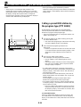
<U.K. and Europe models>
<Modèles pour le Royaume-Uni et l’Europe>
<Großbritannien- und Europa-Modelle>
<Modell för Storbritannien och Europa>
<Modelli per Gran Bretagna e l’Europa>
<Modelos para Reino Unido y Europa>
<Modellen voor Groot-Brittannië en Europa>
RDS MODE
FREQ/PS/PTY/RT/CT
PTY SEEK
MODE
START
VOLUME
INPUT SELECTOR
CD/TAPE/TUNER/AUX/PHONO
POWER
PTY SELECTOR
STEREO RECEIVER
RX–S75
PHONES DISPLAY DOWN UP
TUNER PRESET
A/B/C/D/E
TIMER
MEMORY
TIME ADJ
DOWN
HOUR
UP
MINUTE
TUNING
AUTO/MAN'L
SEC
BAND AUTO MEMO
TIMER REC
BASS
–+
TREBLE
–+
BALANCE
LR
0I0
Active Servo
Technology
MHz
MEMORY PTY H AUTO TUNING STEREO TUNED
SLEEP TIMER
VCD WXYH
IJ K LMNOPQR S T U
BC D
FN G H J
E
I

66
3 KXW-S75
4 NX-S75
CASSETTE DECK
KXW–S75
EJECT EJECT
MODE
DUBBING REC/PAUSE
NORM HIGH
OFF B C
PLAYBACK RECORD/PLAYBACK
DECK A DECK B
DIRECTION
PLAY
NR
`
Z[\]
a
bce h kdij
l
a
fg
m
n

77
1234 5
CD
678
6789 0
1234 5
TIME
PROG
TAPE EDIT +10
ABCDE
REPEAT
RANDOM
STOP
PLAY/PAUSE OPEN/CLOSE
MODE
DISC SKIP
TUNER
DECK
A/B
PLAY STOP PLAY
TAPE
INPUT
REC/PAUSE
-
+
-
+
EFFECT LEVEL
SP/PHONES
MODE DSS
POWER SLEEP
DISPLAY
VOLUME
1
2
3
4
5
6
89
0
A
B
C
7
5
2
3
1
6
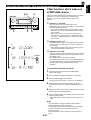
0.2 m – 6 m
(8” – 20’)
30°
30°
7
1234 5
CD
678
6789 0
1234 5
TIME
PROG
TAPE EDIT +10
ABCDE
REPEAT
RANDOM
STOP
PLAY/PAUSE OPEN/CLOSE
MODE
DISC SKIP
TUNER
D
E
F
HIJK L
M
N
O
P
G
DECK
A/B
PLAY STOP PLAY
TAPE
INPUT
REC/PAUSE
-
+
-
+
EFFECT LEVEL
SP/PHONES
MODE DSS
POWER SLEEP
DISPLAY
VOLUME
QR
S
T
U
V
W

88
8
B
PHONES
9
To AC outlet
Vers la prise c.a.
Zur Netzsteckdose
Till nätuttag
Alla presa AC
Al tomacorriente
Naar wisselstroom-stopcontact
0
A
DECK
A/B
INPUT
REC/PAUSE
-
+
-
+
EFFECT LEVEL
SP/PHONES
MODE DSS
POWER SLEEP
DISPLAY
VOLUME

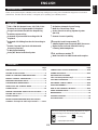
E-1
English
ENGLISH
INTRODUCTION
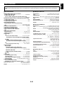
CONTENTS
Page
PRECAUTIONS..................................................................2-3
SETTING UP THE SYSTEM .................................................3
NAMES OF CONTROLS AND INDICATORS....................4-5
REMOTE CONTROL TRANSMITTER................................5-6
REMOVING THE FRONT GRILLE ........................................6
LISTENING WITH HEADPHONES........................................6
OPEN/CLOSE THE CONTROL DOOR .................................6
CONNECTIONS..................................................................7-8
TURNING THE POWER ON/OFF TO THIS SYSTEM...........8
SETTING THE CLOCK..........................................................9
SOUND CONTROL..............................................................10
DIGITAL SUPER SURROUND (DSS) PROCESSOR
CONTROL
<Except U.K. and Europe models>.........10-11
Page
COMPACT DISC PLAYER OPERATION.......................11-18
TUNING OPERATION ....................................................19-21
RECEIVING RDS STATIONS
<U.K. and Europe models only> ...............................22-25
TAPE DECK OPERATION ............................................26-29
RECORDING COMPACT DISCS ...................................30-35
OTHER RECORDINGS...................................................36-37
HOW TO USE THE BUILT-IN TIMER.............................38-41
USING EXTERNAL UNITS..................................................42
MAINTENANCE...................................................................43
TROUBLESHOOTING.........................................................44
SPECIFICATIONS................................................................45
Thank you for purchasing this YAMAHA product. We hope it will give you many years of trouble-free enjoyment. For the best
performance, read this manual carefully. It will guide you in operating your YAMAHA product.
FEATURES
•
75W + 75W (6Ω) Output Power, 10% THD, 1 kHz
•
Random Access Programmable CD Playback
•
Single Track/Entire Disc/All Disc Repeat Play
•
Random-sequence Play
•
Automatic Synchronized Recording with CD
Playback
•
Automatic CD Editing Function for Recording to
Tape
•
Double Cassette Tape Deck with Automatic
Reversing Function
•
2-Way Speed Dubbing
•
Dolby B/C Noise Reduction System
•
40 Station Automatic Preset Tuning
•
Multi-Use Timer/Sleep Timer
•
Active Servo Processing Speaker System
(NX-S75)
•
Remote Control Capability
<
Except U.K. and Europe models >
•
4-Mode Digital Super Surround (DSS) Processor
•
Digital Super Surround Effective Even by
Listening with Headphones
<
U.K. and Europe models >
•
Multi-Functions for RDS Broadcast Reception
For basic source play, the following illustrations on top of
pages will help you to look for the section you need.
......CD playback ......Tuning
......Tape playback/recording

E-2
NOTE
Please check the copyright laws in your country to record from
records, compact discs, radio, etc. Recording of copyright material
may infringe copyright laws.
IMPORTANT
Please record the serial number of this unit in the space below.
Serial No.:
The serial number is located on the rear of the unit.
Retain this Owner’s Manual in a safe place for future reference.
WARNING
TO REDUCE THE RISK OF FIRE OR ELECTRIC SHOCK, DO
NOT EXPOSE THIS APPLIANCE TO RAIN OR MOISTURE.
CAUTION (FOR CANADA MODEL)
TO PREVENT ELECTRIC SHOCK, MATCH WIDE BLADE OF
PLUG TO WIDE SLOT AND FULLY INSERT.
FOR CANADIAN CUSTOMER
THIS CLASS B DIGITAL APPARATUS MEETS ALL
REQUIREMENTS OF THE CANADIAN INTERFERENCE-
CAUSING EQUIPMENT REGULATIONS.
PRECAUTIONS: READ THIS BEFORE OPERATING YOUR UNIT
•
CD pickup
Leave the power on with no disc in the unit until normal
playback is possible (about 1 hour).
•
Tape head
Leave the power on with no cassette in the unit until normal
playback is possible (about 1 hour).
Note
If condensation forms on the tape head, foreign matter may
accumulate during use.
•
Remote control
Wipe off condensation on the transmitter window with a soft
cloth before operating the unit.
■ To assure the finest performance, please read this manual
carefully. Keep it in a safe place for future reference.
■ This system is equipped with the newly developed Active Servo
Processing Speaker System. It is not designed for use with
conventional speakers. Therefore, do not attempt to connect
other speakers than the provided speaker system.
■ Choose the installation location of this unit carefully. Avoid
placing it in direct sunlight or close to a source of heat. Also avoid
locations subject to vibration and excessive dust, heat, cold or
moisture. Keep it away from sources of hum such as
transformers and electric motors.
■ Do not operate this unit upside-down. It may overheat, possibly
causing damage.
■ Never open the cabinet. If something drops into the set, contact
your dealer.
■ The openings on the cabinet assure proper ventilation of the unit.
If these openings are obstructed, the temperature inside the
cabinet will rise rapidly and eventually damage the circuits.
Therefore, avoid placing objects against these openings and do
not install the unit where the flow of air through the ventilation
openings could be impeded.
■ Always set the VOLUME control to minimum before starting the
audio source: increase the volume gradually to an appropriate
level after play has started.
■ When not planning to use this unit for long periods of time (ie.,
vacation, etc.), disconnect the AC power plug from the wall outlet.
■ Grounding or polarization – Precautions should be taken so that
the grounding or polarization of an appliance is not defeated.
■ Do not use force on switches, controls or connection wires. When
moving the unit, first disconnect the power plug and the wires
connected to other equipment. Never pull the wire itself.
■ Do not attempt to clean the unit with chemical solvents; this might
damage the finish. Use a clean, dry cloth.
■ Be sure to read the “TROUBLESHOOTING” section regarding
common operating errors before concluding that the unit is faulty.
■ To prevent lightning damage, disconnect the AC power plug and
the antenna cable when there is an electrical storm.
■ Do not plug the AC power plug to the wall socket before you
finish all connections.
■ Never allow metallic items (e.g. screwdrivers, tools, etc.) to come
near the cassette deck’s record/playback head assembly in this
unit. Doing so may not only scratch or damage the head’s mirror-
smooth finish, it may change the magnetic characteristics of the
heads, causing a deterioration in reproduction performance
quality.
■ Although the cassette deck’s record/playback heads used in this
unit are high quality heads with outstanding reproduction
characteristics, they can become dirty through the use of old
tapes or from dust accumulation over time. This can have a
serious effect on reproduction quality. Clean the heads regularly
with one of the commonly available head cleaners or with
cleaning solutions.
■ The voltage to be used must be the same as that specified on
this unit. Using this product with a higher voltage than that which
is specified is dangerous and may result in a fire or other type of
accident causing damage. YAMAHA will not be held responsible
for any damage resulting from use of this unit with a voltage other
than that which is specified.
■ The sound level at a given volume setting depends on speaker
location and other factors. Care should be taken to avoid
exposure to sudden high levels of sound, which may occur when
turning on the unit with the volume control setting at high, and to
continuous high levels of sound.
■ Sudden temperature changes and storage or operation in an
extremely humid environment may cause condensation inside the
cabinet.
Condensation can cause the unit to malfunction.
To eliminate condensation:
For U.K. customers
If the socket outlets in the home are not suitable for the plug
supplied with this appliance, it should be cut off and an
appropriate 3 pin plug fitted. For details, refer to the
instructions described below.
Note: The plug severed from the mains lead must be
destroyed, as a plug with bared flexible cord is hazardous if
engaged in a live socket outlet.
SPECIAL INSTRUCTIONS FOR U.K. MODEL
IMPORTANT:
The wire in the mains lead are coloured in accordance
with the following code:
Blue: NEUTRAL
Brown: LIVE
The colours of the wires in the mains lead of this
apparatus may not correspond with the coloured
markings identifying the terminals in your plug. Proceed
as follows: the wire which is coloured BLUE must be
connected to the terminal which is marked with the letter
N or coloured BLACK. The wire which is coloured
BROWN must be connected to the terminal which is
marked with the letter L or coloured RED. Making sure
that neither core is connected to the earth terminal of the
three pin plug.

E-3
English
CAUTION FOR CARRYING THIS UNIT
Be sure not to carry or tip this unit with discs remaining in it.
CAUTION FOR MOVING THIS UNIT
Before moving this unit, first remove all discs from the disc table
and close the table by pressing the OPEN/CLOSE button, and
then switch off the power by pressing the POWER switch, and
last, after you confirm that “no disc” is illuminated on the display,
disconnect the power plug from the AC outlet.
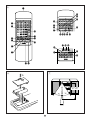
SETTING UP THE SYSTEM
CAUTION 1
Use of controls or adjustments or performance of procedures
other than those specified herein may result in hazardous
radiation exposure.
CAUTION 2
As the laser beam used in this unit is harmful to the eyes, do not
attempt to disassemble the cabinet. Refer servicing to qualified
personnel only.
Laser component in this product is capable of emitting radiation
exceeding the limit for Class 1.
PRECAUTIONS: READ THIS BEFORE OPERATING YOUR UNIT
WARNING
To reduce the risk of fire or electric shock, do not expose this unit to
rain or moisture.
To avoid electrical shock, do not open the cabinet. Refer
servicing to qualified personnel only.
This unit is classified as a CLASS
1 LASER product.
The CLASS 1 LASER PRODUCT
label is located on the rear exterior.
(Europe and U.K. model only)
Laser Diode Properties
•
Material: GaAlAs
•
Wavelength: 780nm
•
Emission Duration: continuous
•
Laser Output: max. 44.6µW*
* This output is the value measured at a distance of about 200mm
from the objective lens surface on the Optical Pick-up Block.
The apparatus is not disconnected from the AC power
source as long as it is connected to the wall outlet, even if
the apparatus itself is turned off.
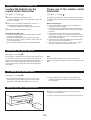
1 cm 1 cm
10 cm
10 cm
10 cm
10 cm 10 cm
10 cm
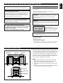
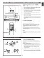
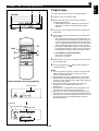
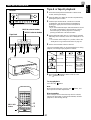
Setup examples
Place this system as illustrated on the left and allow spaces
more than indicated around the system and more than 10 cm
(3-15/16”) behind the system to assure good ventilation. Be
sure not to place another unit or any object on top of the
receiver (RX-S75) to prevent the ventilation holes on the top
panel of the receiver from being obstructed. Otherwise, it
may cause fire or damage to the receiver.
Notes
•
When placing the speakers apart from the main units,
allow a space of at least 10 cm (3-15/16”) from above,
behind and on the both sides of the main units.
•
If the system is put in a rack, the front of it must be fully
opened.
•
Disconnect the AC supply lead from the AC outlet before
connecting or disconnecting any component.
VOLTAGE SELECTOR (General model only)
The voltage selector on the rear panel of this unit must
be set for your local main voltage BEFORE plugging
into the AC main supply.
Voltages are 110/120/220/240V AC, 50/60 Hz.
RX-S75 CDC-S75KXW-S75
RX-S75
CDC-S75
KXW-S75

E-4
NAMES OF CONTROLS AND INDICATORS
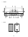
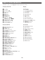
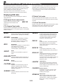
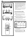
CD player (CDC-S75)
1 Disc Table
2 Stop Button:
3 Disc Selector Buttons
4 TIME Button
5 EDIT Button
6 REPEAT Button
7 RANDOM Button
8 SKIP Buttons: /
(SEARCH Buttons: / )
9 Play/Pause Button: /
0 OPEN/CLOSE Button:
A PLAYXCHANGE Button
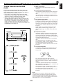
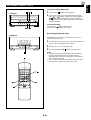
Receiver (RX-S75)
B INPUT SELECTOR Control
C POWER Switch
D Remote Control Sensor
E SP/PHONES Mode Selector Button
F DSS ON/OFF Selector Button
G DSS MODE Selector Button
H VOLUME Control
I PHONES Jack
J DISPLAY Button
K TUNER PRESET DOWN/UP Buttons
L A/B/C/D/E (TIMER) Button
M MEMORY (TIME ADJUST) Button
N TUNING DOWN (HOUR) Button
O TUNING UP (MINUTE) Button
P AUTO/MAN’L (SEC) Button
Q BAND Selector Button
R AUTO MEMORY (TIMER REC) Button
S BASS Tone Control
T TREBLE Tone Control
U BALANCE Control
V INPUT SELECTOR (PTY SELECTOR) Control
W PTY SEEK MODE Button
X RDS MODE Selector Button
Y PTY SEEK START Button
Display
For CD player
1 Track Number Indicator
2 (S, F) REPEAT Indicator
3 Time Display
4 Play Indicator:
5 Disc Indicator
6 EDIT Indicator
7 Tape Side Indicator
8 Music Calendar Indicator
9 Music Calendar OVER Indicator
0 RANDOM Play Indicator
A PROGRAM Indicator
For receiver
B Preset Number Indicator
C Band Indicator
D Station Frequency Display
E TUNED Indicator
F MEMORY Indicator
G AUTO TUNING Indicator
H STEREO Indicator
I SLEEP Indicator
J TIMER Set Indicator
K Effect Level Indicator
L DSS Mode Indicators
M Phones Mode Indicator
N PTY H Indicator
(See figure 1 and 2 on page 33 – 55 at the beginning part of this manual.)

E-5
English
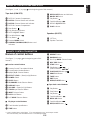
Tape deck (KXW-S75)
Z DECK A Cassette Compartment
[ DECK A Selector Button and Indicator
\ DECK B Selector Button and Indicator
] DECK B Cassette Compartment
` Stop Button:
a Play Direction Indicators
b DECK A EJECT Button
c Fast Wind Button:
d Play Button:
e Reverse MODE Switch
f DUBBING (NORMAL/HIGH) Buttons and
Indicators
g REC/PAUSE Button and Indicator
h DOLBY NR Switch
i Play Button:
j Fast Wind Button:
k DECK B EJECT Button
l PLAY Indicator
Speakers (NX-S75)
m YST Port
n Speaker Terminals
NAMES OF CONTROLS AND INDICATORS
(See figure 3 and 4 on page 66 at the beginning part of this manual.)
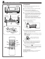
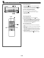
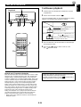
Names of control buttons
(See figure 5 on page 77 at the beginning part of this
manual.)
■
Receiver control buttons
1 Remote Control Transmitter Window
2 Preset Station Number Buttons
3 A, B, C, D, E Selector Buttons
4 EFFECT LEVEL – (Down)/+ (Up) Buttons
5 POWER Switch
6 SLEEP Button
7 SP/PHONES Mode Selector Button
8 DISPLAY Button
9 VOLUME – (Down)/+ (Up) Buttons
0 TUNER Input Selector Button
A INPUT Selector Button
B DSS On/Off Button
C DSS MODE Selector Button
■ CD player control buttons
D Track Number Input Buttons
E TIME Button
F REPEAT Button
G RANDOM Button
H Disc Play MODE Selector Button
I DISC SKIP Button
J STOP Button:
K Skip Buttons: /
(Search Buttons: / )
L PLAY/PAUSE Button:
M PROGRAM Button
N TAPE Button
O EDIT Button
P OPEN/CLOSE Button:
■
Tape deck control buttons
Q Play Button:
R Stop Button:
S Play Button:
T Fast Wind Button:
U DECK A/B Button
V Fast Wind Button:
W REC/PAUSE Button:
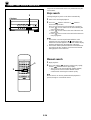
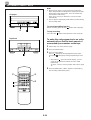
REMOTE CONTROL TRANSMITTER
* Parts in shaded areas on the figure 5 are not equipped on U.K. and Europe models.
This manual mainly uses illustrations for U.K. and Europe models.

E-6
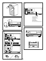
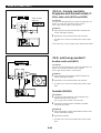
(See figure 8 on page 88.)
The front grille is fastened to the enclosure at four points, and
can be removed if desired. To remove the grille, hold on to
both sides and slowly pull straight away from the speaker. To
reattach, line up the four pegs on the speaker with the four
corresponding holes on the inside surface of the grille and
push gently.
Note
When the grille is removed, take care not to touch the
speaker units with your hands or to exert excessive force with
tools.
REMOVING THE FRONT GRILLE
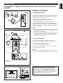
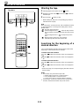
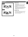
Loading the batteries for the
remote control transmitter
(See figure 6 on page 77.)
1 Remove the battery compartment cover.
(Press the left edge of the cover to right with a finger, and
then pull it upward.)
2 Insert 2 “AA” size batteries (UM/SUM-3, R6, HP-7 or
equivalent) into the battery compartment.
* Installing the batteries improperly may cause failure.
3 Replace the battery compartment cover.
Precautions for battery use
•
Insert the batteries according to the direction indicated in
the battery compartment.
•
Replace all batteries with new ones at the same time.
•
Remove the batteries if they are weak or if the unit is not
in use for long periods.
•
Don’t mix normal batteries with rechargeable batteries.
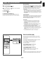
Proper use of the remote control
transmitter
(See figure 7 on page 77.)
Aim (within the range of 60° with no obstacles) the remote
control transmitter at the remote control sensor and operate
as shown.
Notes concerning use
•
Replace the batteries if control distance decreases or
operation becomes unstable.
•
Periodically clean the transmitter window on the remote
control transmitter and the sensor on the main unit with a
soft cloth.
•
Exposing the sensor on the main unit to strong light
(especially an inverter type of fluorescent lamp etc.) may
interfere with operation. In this case, reposition the main
unit to avoid direct lighting.
•
Keep the remote control transmitter away from moisture,
excessive heat, shock and vibrations.
•
The remote control transmitter’s usable range is within
0.2m (8”) and 6m (20’) away from the sensor.
REMOTE CONTROL TRANSMITTER
(See figure 9 on page 88.)
•
Be sure that your headphones have a 3.5 mm (1/8”)
diameter plug and are between 16 ohms and 50 ohms
impedance. Recommended impedance is 32 ohms.
•
When headphones are connected, the speakers are
defeated automatically. Adjust the VOLUME control for
desired volume.
LISTENING WITH HEADPHONES
OPEN/CLOSE THE CONTROL DOOR
When it is not necessary to operate controls inside the
control door, close the door.
To open or close the door, press the right edge until it clicks.

E-7
English
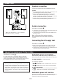
AM
ANT
GND
FM
ANT
75Ω
UNBAL.
Antenna connection
(1) Supplied FM antenna
Connect the FM antenna wire to the corresponding terminal
and direct the FM antenna wire to the direction where the
strongest signal can be received.
(2) Supplied AM (MW/LW) loop antenna
Connect the AM (MW/LW) loop antenna wires to the
corresponding terminals. Position the AM (MW/LW) loop
antenna for optimum reception. Place the AM (MW/LW) loop
antenna on a shelf etc., or install it on the rack or wall with
screws (not supplied).
Notes
•
When static is still heard even after adjusting the position
of the AM (MW/LW) loop antenna, try reversing the wire
connections (top to bottom).
•
Do not place the AM (MW/LW) loop antenna on the unit. It
will result in noise generation, since the unit is equipped
with digital electronics. Place the AM (MW/LW) loop
antenna away from the unit.
(3) External FM antenna
Use an external FM antenna instead of an indoor FM
antenna if you need better reception. Consult your dealer.
(4) External AM (MW/LW) antenna
Use an external AM (MW/LW) antenna if you need better
reception. Consult your dealer.
Note
When using an external AM (MW/LW) antenna, be sure to
keep the wire of the AM (MW/LW) loop antenna connected.
CONNECTIONS
AM
ANT
GND
FM
ANT
75Ω
UNBAL.
or
Earth rod
7.5 m (25 feet)
15 m (49 feet)
* For U.K. and Europe models, “AM” is replaced by
“MW LW”.
(1)
(2)
(3)
(4)
FREQUENCY STEP switch (General model only)
Because the interstation frequency spacing differs in
different areas, set the FREQUENCY STEP switch
(located at the rear) according to the frequency spacing in
your area. Before setting this switch, disconnect the AC
supply lead of this unit from the AC outlet.
Never plug the AC supply lead of this system into the AC outlet until all connections are
completed.
100 kHz
10 kHz
FM
AM
50 kHz
9 kHz
FREQUENCY STEP

E-8
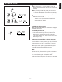
(Black wire with white line → plus (+) terminal,
black wire → minus (–) terminal)
STANDBY mode
While the power is on, pressing the POWER switch (or the
POWER switch on the remote control transmitter) switches
the system to the STANDBY mode. (In this mode, the
display shows only the time.) In this mode, main voltage is
still present inside the system. If you want to switch off the
system completely, disconnect the AC power plug from the
AC outlet.
TURNING THE POWER ON/OFF TO THIS SYSTEM
(See figure B on page 88.)
If the AC supply lead is connected to the AC outlet, this
system can be turned ON and OFF (STANDBY mode) by
pressing the POWER switch on the front panel of RX-S75 or
the POWER switch on the remote control transmitter.
Automatic power-on function
Even when the power is off, pressing the following buttons
will turn the system on, and then perform their own functions.
For Tuner operation
•
TUNER on the remote control transmitter
For CD player operation
•
/ , disc selector buttons, OPEN/CLOSE on the front
panel of CDC-S75
•
/ , OPEN/CLOSE on the remote control transmitter
For tape deck operation
•
, , DECK A, DECK B on the front panel of KXW-S75
•
, , DECK A/B on the remote control transmitter
Automatic power-off function
When
the CD or TAPE input source is selected, if there is no
operation and in the stop mode for about 30 minutes, the
system will be turned off automatically.
Speaker connection
Connect each speaker wire to the SPEAKERS terminals.
Cautions
•
Do not let the bare speaker wires touch each other as this
could damage the receiver and/or speakers.
•
When connecting the speakers to the unit, be sure to
connect the speaker wires properly. Do not make a
mistake from the right channel to the left channel and from
the plus (+) terminal to the minus (–) terminal.
•
Do not connect these SPEAKERS terminals to speakers
other than the provided speaker system NX-S75.
System connection
(See figure 0 on page 88.)
•
Connect the red connector on the rear of CDC-S75 to the
red socket on the rear of RX-S75.
•
Connect the black connector on the rear of KXW-S75 to
the black socket.
How to disconnect the system connector
Grasp both sides of the connector to disconnect the
connector.
Connecting the AC supply lead
(See figure A on page 88.)
•
After connecting the speakers and system connectors,
plug the AC supply lead into a convenient AC outlet.
•
Unplug the AC supply lead from the AC outlet if the unit is
not to be used for a long period of time.
CONNECTIONS
R L
Right
Left

E-9
English
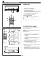
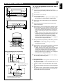
1 While the power is on, press the DISPLAY button to
display the time. If the power is off, you can proceed to the
next step.
2 While pressing the TIME ADJ button, press the HOUR
button and set the hour.
* Press the HOUR button once to advance the time by 1
hour. Press and hold to advance continuously.
3 While pressing the TIME ADJ button, press the MINUTE
button and set the minute.
* Press the MINUTE button once to advance the time by
1 minute. Press and hold to advance continuously.
* The hour setting will not advance even if minute is
advanced from “59” to “00”.
To display the time by “second”
While pressing the SEC button, the current time is displayed
by minute and second.
To reset the second to “00”
While pressing the SEC button, press the TIME ADJ button.
* If the current second is lower than 30, it is reset to 00.
* If the current second is higher than 30, the minute is
advanced by 1 minute and the second is reset to 00.
(If the current minute is “59”, in this case, the hour is also
advanced by 1 hour.)
In the event of a power failure or when the AC supply
lead is disconnected.
The time display will go out, however, the clock will function
for about 5 minutes without power supply. So you do not
have to reset the time if the AC power supply is resumed
within about 5 minutes.
When the AC power supply is resumed after more than 5
minutes pass without power supply, the time display will flash
on and off to indicate that the time must be reset.
Note
If this system is left for several minutes without setting the
time after the AC power lead of this system is connected to
the AC outlet, there may be a case that the display is turned
into a demonstration mode. (This mode is virtually
unnecessary for using this system.)
In this case, first turn the power on by pressing the POWER
switch to cancel the mode, and then set the time.
DISPLAY
MEMORY
TIME ADJ
DOWN
HOUR
UP
MINUTE
TUNING
MEMORY
TIME ADJ
DOWN
HOUR
UP
MINUTE
TUNING
SETTING THE CLOCK
Changes.
Changes.
SecondMinute
1
3
2
AUTO/MAN'L
SEC

E-10
VOLUME
0I0
-
+
VOLUME
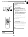
SOUND CONTROL
Volume
Front panel operation
Rotate the VOLUME control towards 10 to increase the
volume, and towards 0 to decrease the volume.
Remote control operation
Press the VOLUME + button to increase the volume and the
VOLUME – button to decrease the volume.
Balance
Adjust the balance of the output volume to the left and right
speakers to compensate for sound imbalance caused from
the speaker settings or the listening room condition.
Turn this clockwise to emphasize the right and
counterclockwise for the left.
Tone
BASS : Turn this clockwise to increase (or counter-
clockwise to decrease) the low frequency
response.
TREBLE : Turn this clockwise to increase (or counter-
clockwise to decrease) the high frequency
response.
BALANCE
LR
BASS
–+
TREBLE
–+
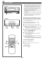
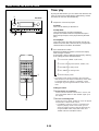
The Digital Super Surround (DSS) Processor built into this
unit presents you with sound effect which simulates acoustic
environments suitable for some genres of music.
This unit provides the following 4 DSS modes.
Mode
ROCK
JAZZ
CLASSIC
RELAXED
Feature
Low frequency and high frequency of the
source sound are somewhat emphasized.
It is suitable for listening to rock or pop music.
This mode creates a sound field with much
presence adding spatial effect as if music
instruments are coming in front.
The sound stage is expanded.
It is suitable for listening to classic music, etc.
This mode is suitable for easy-listening
music. The sound is reproduced with a soft,
comfortable atmosphere.
MODE
ROCK
JAZZ
CLASSIC
RELAXED
DIGITAL SUPER SURROUND (DSS) PROCESSOR CONTROL
<
Except U.K. and Europe models
>

E-11
English
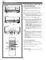
COMPACT DISC PLAYER OPERATION
Care of compact discs
Compact discs are fairly resistant to damage, however
mistracking can occur due to an accumulation of dirt on the
disc surface.
Follow the guidelines below for maximum enjoyment from
your CD collection and player.
•
Do not write on either side of the disc, particularly the non-
label side. Signals are read from the non-label side. Do
not mark this surface.
•
Keep your discs away from direct sunlight, heat and
excessive moisture.
•
Always hold the CDs by the edges. Fingerprints, dirt or
water on the CDs can cause noise or mistracking. If a CD
is dirty or does not play properly, clean it with a soft, dry
cloth, wiping straight out from the center, along the radius.
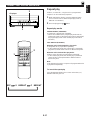
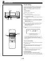
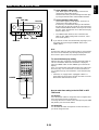
Listening to the music with the
DSS
1 Press the DSS ON/OFF selector button so that the effect
level indicator lights up on the display.
2 Select a desired DSS mode by pressing the DSS MODE
selector button once or more until the name of the desired
mode appears on the display.
3 Playback a source. (For source playback, refer to other
sections described later.)
4 Adjust the level of effects by pressing the EFFECT LEVEL
down (–) or up (+) button.
* Effect level can be checked with the effect level indicator
on the display.
* Each of the DSS modes can be set with a different effect
level.
If you will not use the DSS
Press the DSS ON/OFF selector button so that the effect
level indicator on the display goes off.
When listening with headphones
Press the SP/PHONES mode selector button so that the
phones mode indicator lights up on the display.
You can obtain a DSS effect suitable for the headphone
listening.
If not using headphones, the SP/PHONES mode selector
button should be pressed so that the phones mode indicator
on the display goes off.
Note
DSS effect is also recorded along with a source. If you wish
to record a source without DSS effect, turn the DSS off when
recording.
ROCK
DSS
12345
CD
678
67890
12345
TIME
PROG
TAPE EDIT +10
ABCDE
REPEAT
RANDOM
STOP
PLAY/PAUSE OPEN/CLOSE
MODE
DISC SKIP
TUNER
DECK
A/B
PLAY STOP PLAY
TAPE
INPUT
REC/PAUSE
-
+
-
+
EFFECT LEVEL
SP/PHONES
MODE DSS
POWER SLEEP
DISPLAY
VOLUME
DIGITAL SUPER SURROUND (DSS) PROCESSOR CONTROL
<
Except U.K. and Europe models
>
Phones mode indicator
1 2
SP/PHONES
1
2
4
SP/PHONES
Effect level indicator

E-12
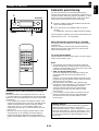
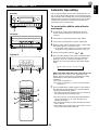
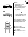
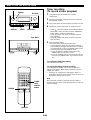
CD playback
1 Select the CD position with the INPUT SELECTOR
control, watching the display.
2 Press the OPEN/CLOSE button to open the disc table.
3 Place discs on the trays, label side up.
* Up to three discs can be loaded on the trays.
* 8 cm (3”) discs may be played without an adaptor.
4 Press the OPEN/CLOSE button to close the disc table.
* The total number of tracks and the total playing time of
the disc being selected will be displayed for several
seconds.
* The music calendar will be displayed only for the
number of tracks on the disc being selected.
* If the compact disc contains more than 20 tracks, the
“OVER” indicator will light up on the music calendar.
5 If necessary, change the disc play mode by pressing the
disc play MODE selector button on the remote control
transmitter while watching the display.
Single disc play mode: Only a designated disc is played
back.
All disc play mode: All discs on the disc table are played
back sequentially.
6 If necessary, select another disc by pressing the DISC
SKIP button on the remote control transmitter once or
more (so that the corresponding disc tray number is
located on top of the disc indicator).
7 Press the play/pause / button to start playback from
track 1.
* The “ ” indicator will appear and playback will begin.
As the playback of each track on the music calendar is
finished, that track number will go out.
For easier operation
Pressing the disc selector button (1, 2 or 3) will select the
disc directly, and playback will begin from track 1
automatically.
COMPACT DISC PLAYER OPERATION
Total number of tracks
The disc on the tray located on top of this
indicator is now being selected.
Music calendar Total playing time
12345
CD
678
67890
12345
TIME
PROG
TAPE EDIT +10
ABCDE
REPEAT
RANDOM
STOP
PLAY/PAUSE OPEN/CLOSE
MODE
DISC SKIP
TUNER
DECK
A/B
PLAY STOP PLAY
TAPE
INPUT
REC/PAUSE
-
+
-
+
EFFECT LEVEL
SP/PHONES
MODE DSS
POWER SLEEP
DISPLAY
VOLUME
TOTAL
2345 678910
11 12
1
Lights up only when the all
disc play mode is selected.
POWER
Receiver
1
CD Player
Disc selector buttons
7, 11, 22
2, 4
3
6
5
2, 4
7, 11, 22
1
POWER
Seite wird geladen ...
Seite wird geladen ...
Seite wird geladen ...
Seite wird geladen ...
Seite wird geladen ...
Seite wird geladen ...
Seite wird geladen ...
Seite wird geladen ...
Seite wird geladen ...
Seite wird geladen ...
Seite wird geladen ...
Seite wird geladen ...
Seite wird geladen ...
Seite wird geladen ...
Seite wird geladen ...
Seite wird geladen ...
Seite wird geladen ...
Seite wird geladen ...
Seite wird geladen ...
Seite wird geladen ...
Seite wird geladen ...
Seite wird geladen ...
Seite wird geladen ...
Seite wird geladen ...
Seite wird geladen ...
Seite wird geladen ...
Seite wird geladen ...
Seite wird geladen ...
Seite wird geladen ...
Seite wird geladen ...
Seite wird geladen ...
Seite wird geladen ...
Seite wird geladen ...
Seite wird geladen ...
-
 1
1
-
 2
2
-
 3
3
-
 4
4
-
 5
5
-
 6
6
-
 7
7
-
 8
8
-
 9
9
-
 10
10
-
 11
11
-
 12
12
-
 13
13
-
 14
14
-
 15
15
-
 16
16
-
 17
17
-
 18
18
-
 19
19
-
 20
20
-
 21
21
-
 22
22
-
 23
23
-
 24
24
-
 25
25
-
 26
26
-
 27
27
-
 28
28
-
 29
29
-
 30
30
-
 31
31
-
 32
32
-
 33
33
-
 34
34
-
 35
35
-
 36
36
-
 37
37
-
 38
38
-
 39
39
-
 40
40
-
 41
41
-
 42
42
-
 43
43
-
 44
44
-
 45
45
-
 46
46
-
 47
47
-
 48
48
-
 49
49
-
 50
50
-
 51
51
-
 52
52
-
 53
53
-
 54
54


Yamaha CC-75 Benutzerhandbuch
- Kategorie
- Soundbar-Lautsprecher
- Typ
- Benutzerhandbuch
in anderen Sprachen
- English: Yamaha CC-75 User manual
- français: Yamaha CC-75 Manuel utilisateur
- español: Yamaha CC-75 Manual de usuario
- italiano: Yamaha CC-75 Manuale utente
- русский: Yamaha CC-75 Руководство пользователя
- Nederlands: Yamaha CC-75 Handleiding
- português: Yamaha CC-75 Manual do usuário
- dansk: Yamaha CC-75 Brugermanual
- polski: Yamaha CC-75 Instrukcja obsługi
- čeština: Yamaha CC-75 Uživatelský manuál
- svenska: Yamaha CC-75 Användarmanual
- Türkçe: Yamaha CC-75 Kullanım kılavuzu
- suomi: Yamaha CC-75 Ohjekirja
- română: Yamaha CC-75 Manual de utilizare
Verwandte Artikel
-
Yamaha GX-50 Bedienungsanleitung
-
-
-
-
-
-
-
-
-
Andere Dokumente
-
Roadstar HIF-6880USMPT Benutzerhandbuch
-
Aiwa CA-DW257 EZS Benutzerhandbuch
-
Aiwa CA-DW50 Operating Instructions Manual
-
NAD L40 Bedienungsanleitung
-
Bose WAVE MUSIC SYSTEM IV Bedienungsanleitung
-
Panasonic SG152 Bedienungsanleitung
-
Roadstar CLR-2540UMPSL Benutzerhandbuch
-
Denver MCU-5301 Benutzerhandbuch
-
Philips MC165 Benutzerhandbuch
-
Canton DSS 303 Bedienungsanleitung