
Bedienungsanleitung Crimpzange HARTING Han-Fast® Lock
Rev.: 2016-09-19 1 / 6
Vor Beginn aller Arbeiten Betriebsanleitung lesen!
Bedienungsanleitung
Crimpzange HARTING Han-Fast® Lock

Rev.: 2016-09-19 2 / 6
Bedienungsanleitung Crimpzange HARTING Han-Fast® Lock
Inhaltsverzeichnis
1. Allgemeines 3
2. Verwendungszweck 3
3. Beschreibung 3
4. Wechsel / Einbau Crimpeinsatz und Kontaktaufnahme 4
5. Crimpvorgang 4
6. Notentriegelung der Zwangssperre 5
7. Einstellung der Crimphöhe 5
8. Garantie 6
9. Wartung und Instandhaltung 6
HARTING Electric GmbH &Co. KG
Wilhelm-Harting-Straße 1 | D-32339 Espelkamp
Postfach 14 73 | D-32328 Espelkamp
Telefon: +49 5772 47-0 | Fax: +49 5772 47-124
E-Mail: [email protected] | Internet: www.HARTING.com
1. Auflage 2012
© HARTING Electric GmbH & Co. KG, Espelkamp
Autor: HARTING
Redaktion: HARTING
Alle Rechte, auch die der Übersetzung, vorbehalten.
Kein Teil dieses Handbuches darf ohne schriftliche Zustimmung der Firma HARTING Electric GmbH & Co. KG,
Espelkamp, in irgendeiner Form (Druck, Fotokopie, Mikrofilm oder einem anderen Verfahren) reproduziert
oder unter Verwendung elektronischer Systeme verarbeitet, vervielfältigt oder verbreitet werden.
Änderungen vorbehalten.
Alle Marken- und Produktnamen sind Warenzeichen oder eingetragene Warenzeichen der jeweiligen Titelhalter.

Rev.: 2016-09-19 3 / 6
Bedienungsanleitung Crimpzange HARTING Han-Fast® Lock
1. Allgemeines
Die HARTING-Crimpzange ist nach dem neuesten Stand der Technik und den anerkannten sicherheitstechnischen
Regeln hergestellt. Die Zange darf nur in technisch einwandfreiem Zustand sowie sicherheits- und
gefahrenbewusst benutzt werden und ist nur für den in der Bedienungsanleitung beschriebenen Zweck zu
verwenden.
Eine eigenmächtige Veränderung oder eine nicht bestimmungsgemäße Verwendung
der HARTING Crimpzange schliesst eine Haftung des Herstellers für daraus
resultierende Schäden aus. Nur an spannungsfreien Leitern arbeiten!
Achtung
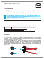
2. Verwendungszweck
Je nach Ausführung zum Vercrimpen von geraden und gewinkelten Kontakten der Serie Han-Fast® Lock:
Art. Nr. Crimpzange Kontaktausführung Querschnitt mm²
Kontaktaufnahme Abisolierlänge Kabel
09 99 000 0881 gerade 1,5 / 2,5
ja
7,5mm
09 99 000 0831 gerade 4,0 / 6,0 / 10,0
09 99 000 0877 gewinkelt 1,5 / 2,5
nein
09 99 000 0876 gewinkelt 4,0 / 6,0 / 10,0
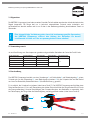
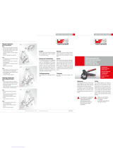
3. Beschreibung
Die HARTING Crimpzange besteht aus einer Grundzange 1 mit Stellscheibe 2 und Notentriegelung 3, einem
Crimpeinsatz (je nach Anwendung) 4, zwei Befestigungsschrauben 5 für die Crimpeinsätze und bei Bedarf
aus einer Positionierhilfe/Kontaktaufnahme 6 (Kontaktausführung „gerade“).
Es ist möglich, die Crimpkraft zu justieren (siehe hierzu Punkt 7). Die HARTING Crimpzange verfügt über einen
Ratschenmechanismus. Erst nach Überwindung der letzten Raststufe öffnet die Zange automatisch (Prinzip
der Zwangsvollendung). Um eine Beschädigung der Crimpeinsätze bzw. des Verbinders zu vermeiden, kann
bei Fehlcrimpung die Zange über die Notentriegelung vorzeitig geöffnet werden (siehe hierzu Punkt 6).
1
3
2
5
4
6

Rev.: 2016-09-19 4 / 6
Bedienungsanleitung Crimpzange HARTING Han-Fast® Lock
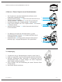
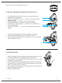
4. Wechsel / Einbau Crimpeinsatz und Kontaktaufnahme
• Der Crimpeinsatz sowie die Kontaktaufnahme können je nach
Anwendung ausgewechselt werden.
• Innensechskantschrauben 1+2 mittels Innensechskantschlüssel (im
Griff) 2,5 mm ausschrauben.
• Crimpeinsatzober- 3 und Unterteil 4 aus der Zange entnehmen.
• Einsetzen des optionalen Crimpeinsatzober- 3 und unterteils 4
• Zange soweit schließen, dass sich Crimpeinsatzober- 3 und unterteil
4 zentrieren können.
• Innensechskantschrauben 1+2 mittels Innensechskantschlüssel
2,5mm festziehen.
• Zur Montage einer optionalen Kontaktaufnahme („gerade“
Kontaktausführung) Schraube 2 an Crimpeinsatzunterteil durch
Schraube M 4x15 6 ersetzen.
• Kontaktaufnahme 5 an Zange mittels Innensechskantschlüssel
befestigen (ggf. auf gegenüberliegender Seite gegenhalten).
6
5
5. Crimpvorgang
1. Crimpeinsatz und ggf. Kontaktaufnahme montieren (siehe Punkt 4.).
2. Kabel auf angepasste Länge (Herstellerangaben beachten) abisolieren.
3. Verbinder entsprechend dem Querschnitt in Crimpeinsatz oder die
entsprechende Stelle im Locator einlegen und mittels Zangendruck
halten, Kabel in Verbinder einführen.
4. Zange schließen und nach Überwindung der letzten Raststufe öffnen
(Zwangssperre).
5. Vercrimpten Kontakt entnehmen.
2
3
4
1

Rev.: 2016-09-19 5 / 6
Bedienungsanleitung Crimpzange HARTING Han-Fast® Lock
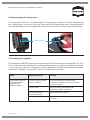
6. Notentriegelung der Zwangssperre
Die Zwangssperre öffnet sich nach Vollendung des Crimpvorganges automatisch. Bei einer Unterbrechung
des Crimpvorganges müssen zum Öffnen der Zwangssperre die Zangenschenkel etwas zusammengedrückt
und die Notentriegelung mit dem beiliegendem Innensechskantschlüssel mit Fähnchengriff betätigt werden.
Notentriegelung
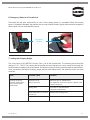
7. Einstellung der Crimphöhe
Die Crimpkraft der HARTING Crimpzange ist vom Werk eingestellt. Die Handkraft im Leerhub beträgt 130 – 180
N. Die Crimpmatrize und Handzange sind so aufeinander abgestimmt, dass bei dieser Handkraft ein optimaler
Crimp erzeugt wird. Sollte das Crimpergebnis nicht der geforderten Spezifikation des Verbinderherstellers
entsprechen (Crimphöhe, Auszugskraft), so kann das folgende Ursachen haben:
Fehler mögliche Ursache Lösung
Crimpergebnis entspricht
nicht der geforderten
Spezifikation des
Verbinderherstellers
Falscher Crimpeinsatz oder
falsches Crimpnest
Den für die Anwendung entsprechenden
Crimpeinsatz montieren und mit dem richtigen
Crimpnest arbeiten
Falsches Kabel Kabel gemäß den Spezifikationen des
Verbinderherrstellers verwenden
Anwendungsbedingter
Verschleiß der Zange
Nachjustieren der Crimpkraft
Verschlissender Crimpeinsatz Crimpeinsatz austauschen um Schäden zu
vermeiden

Rev.: 2016-09-19 6 / 6
Bedienungsanleitung Crimpzange HARTING Han-Fast® Lock
8. Garantie
Die Crimp- Systemzange unterliegt einer sorgfältigen Qualitätskontrolle. Es gelten die allgemeinen
Garantiebestimmungen.
9. Wartung und Instandhaltung
Die Crimp-Systemzange muss vor Arbeitsbeginn in einem ordnungsgemäßen und sauberen Zustand sein.
Crimprückstände sind zu entfernen. Die Gelenke sind regelmäßig mit leichtem Maschinenöl zu ölen und vor
Verschmutzung zu schützen. Es ist darauf zu achten, dass alle Bolzen durch Sicherungsringe gesichert sind.
Der Festsitz der Schaftschraube zur Sicherung der Stellscheibe ist zu prüfen. Reparaturen an der Crimpzange
sind grundsätzlich vom Zangenhersteller oder einer autorisierten Fachwerkstatt vorzunehmen.
1. Entfernen der Schaftschraube 1 mit einem Schraubendreher.
2. Wenn die Stellscheibe 2 gegen den Uhrzeigersinn (+) gedreht wird, wird eine
höhere Crimpkraft und eine kleinere Crimphöhe erreicht.
3. Wird die Stellscheibe im Uhrzeigersinn (-) gedreht, so erhält man eine geringere
Crimpkraft und somit eine größere Crimphöhe. Die Nachjustierung der Handkraft
sollte 180 N nicht überschreiten.
4. Durch Verwendung der Anschraubbohrung 3 kann eine Veränderung der
Crimpkraft um nur eine halbe Kerbe erreicht werden. Dadurch ist eine sehr
feinfühlige Verstellung der Crimpkraft möglich.
5. Schaftschraube einsetzen
6. Vor Benutzung der Zange ist darauf zu achten, dass die Stellscheibe
ordnungsgemäß durch die Schaftschraube gesichert ist.
1
2
Die Crimphöhe sollte regelmäßig durch Fachpersonal der Qualitätskontrolle überprüft
und gegebenenfalls wie nachfolgend beschrieben eingestellt werden.
Achtung
3

Owner’s Manual Crimping Tool HARTING Han-Fast® Lock
Rev.: 2016-09-19 1 / 6
Please read this manual carefully before starting any job!
Owner’s Manual
Crimping Tool HARTING Han-Fast® Lock

Rev.: 2016-09-19 2 / 6
Owner’s Manual Crimping Tool HARTING Han-Fast® Lock
Table of Contents
1. General Information 3
2. Intended Use 3
3. Description 3
4. Changing / Mounting the Crimping Die Set and Locator 4
5. Crimping Procedure 4
6. Emergency Release of Forced Lock 5
7. Setting the Crimping Height 5
8. Warranty 6
9. Maintenance and Service 6
HARTING Electric GmbH &Co. KG
Wilhelm-Harting-Straße 1 | D-32339 Espelkamp
PO Box 14 73 | D-32328 Espelkamp
Telephone: +49 5772 47-0 | Fax: +49 5772 47-124
E-Mail: [email protected] | Internet: www.HARTING.com
1st Edition 2012
© HARTING Electric GmbH & Co. KG, Espelkamp
Author: HARTING
Editor: HARTING
Copyright, as well as translation, reserved.
No part of this manual may be reproduced without written consent from HARTING Electric GmbH & Co.
KG, Espelkamp, in any form (print, hard copy, micro film or any other method or by processing, copying or
distributing through the usage of electronic systems. The information is subject to change without notice.
All name brands and product names are trademarks or registered trademarks of their respective title holders.

Rev.: 2016-09-19 3 / 6
Owner’s Manual Crimping Tool HARTING Han-Fast® Lock
1. General Information
The HARTING-crimping tool is manufactured by using the latest technology and the generally accepted safety
regulations. The pliers may only be used in proper working condition with all safety and hazard regulations in
mind and should be used solely for the purpose, for which it is intended for in this owner’s manual.
Any unauthorized modification or improper use of the HARTING Crimping Tool
excludes the manufacturer from any liability from damages resulting from this. Only
work on disconnected cables and connectors!
Attention
2. Intended Use
Depending upon the type to crimp Han-Fast® Lock series straight and angled connectors:
Item No. of Crimping Tool Contact Type Cross Section in mm²
Locator Length of Cable to be stripped
09 99 000 0881 straight 1,5 / 2,5
yes
7,5mm
09 99 000 0831 straight 4,0 / 6,0 / 10,0
09 99 000 0877 angled 1,5 / 2,5
no
09 99 000 0876 angled 4,0 / 6,0 / 10,0
3. Description
The HARTING Crimping Tool consists of one basic tool 1 with an adjustment plate 2 and an emergency
release lever 3, a die set (depending on application) 4, two fastening screws 5 for the die set and, optionally
a positioning aid/ locator 6 (for “straight” contacts).
The crimp force can be adjusted (see 7. Setting the Crimping Height). The HARTING Crimping Tool Crimpzange
has a ratcheting mechanism. Only after the last ratchet step is reached, the pliers will open automatically
(concept of forced completion). In order to avoid damages to the crimping die set or the connectors, the
pliers may be opened prematurely by engaging the emergency release lever (see also 6. Emergency Release
of Forced Lock).
1
3
2
5
4
6

Rev.: 2016-09-19 4 / 6
Owner’s Manual Crimping Tool HARTING Han-Fast® Lock
4. Changing / Mounting the Crimping Die Set and Locator
• The crimping die set, as well as the locator may be changed out
depending on the application.
• Loosen and remove hex screws 1+2 with an 2,5 mm Allen wrench
(stored in handle).
• Remove the upper (3) and lower (4) die set from the tool.
• Place optional upper (3) and lower (4) die set into the pliers
• Close the pliers until the upper (3) and lower (4) die set meet and
can center themselves.
• Tighten the hex screws 1+2 with an 2,5 mm Allen wrench (stored in
handle).
• in order to mount the optional locator (“straight”) onto the tool,
simply replace the bottom screw (2) with M4x15 screw (6).
• fasten locator onto the pliers with an Allen wrench, (may have to hold
tight on the opposite side).
6
5
5. Crimping Procedure
1. Mount crimping die set and the optional locator onto the pliers (see also
4. Changing / Mounting the Crimping Die Set and Locator).
2. Strip the cable to the appropriate length (please note the cable
manufacturer’s specifications).
3. Place the connector into the appropriate crimping nest of the die set or
the specific place in the locator and hold the connector by pressing the
pliers, insert cable into the connector.
4. Close the pliers and after the last ratcheting point is reached, open the
pliers (forced lock mechanism).
5. Remove crimped contact.
2
3
4
1

Rev.: 2016-09-19 5 / 6
Owner’s Manual Crimping Tool HARTING Han-Fast® Lock
6. Emergency Release of Forced Lock
The forced lock will open automatically as soon as the crimping process is completed. When the crimping
process should be interrupted, the operator has to close the plier handles slightly and activate the emergency
release lever with the enclosed Allen wrench.
Emergency
Release
7. Setting the Crimping Height
The crimp force of the HARTING Crimping Tool is set at the manufacturer. The actuating hand force (idle
setting) is 130 – 180 N. The crimping die set and the tool are matched up in such a manner that through the
hand activation an optimal crimp is produced. Should the crimping result not match the required specifications
of the connector manufacturer (crimping height, pull-out force requirements), the following causes may have
occurred:
Error Possible cause Solution
Crimping results do
not meet specifications
set by the connector
manufacturer
Wrong die set or
wrong crimp nest
Mount the die set appropriate to
the application and ensure contact is placed in the
correct crimp nest
Wrong cable Use cable as specified by the
connector manufacturer
Wear to the tool as a result of
normal use
Readjust the crimping force
Wear of die set Replace die set to avoid damage

Rev.: 2016-09-19 6 / 6
Owner’s Manual Crimping Tool HARTING Han-Fast® Lock
8. Warranty
The crimp system tool is subjected to a thorough quality control process.
General warranty conditions apply.
9. Maintenance and Service
Before starting work, ensure that the crimping tool is clean and in proper working condition.
Crimping residue must be removed. Joints should be oiled regularly with a light mineral oil and must be
protected against dirt. All bolts need to be secured with retaining rings. Check if the setting dial is secured
tightly by the slotted headless screw.
Any repairs of the crimping tool must be performed by the manufacturer or an authorized workshop.
1. Use a screwdriver to remove the slotted headless screw 1.
2. If the setting dial (2) is rotated counter-clockwise (+), a higher crimp force and a
smaller crimp height will be reached.
3. If the setting dial is rotated clockwise (-), the crimp force is reduced and the crimp
height will increase. The newly adjusted crimp force should not exceed 180 N.
4. If bolt aperture 3 is used, the crimp force can be adjusted by only half a notch. A
fine adjustment is hereby possible.
5. Place the slotted headless screw back onto the pliers
6. Prior to using the tool, ensure that the setting dial is properly secured with the
slotted headless screw.
1
2
The crimping height should be monitored by qualified personnel of the quality control
department periodically and should be adjusted by using the following steps:
Attention
3
-
 1
1
-
 2
2
-
 3
3
-
 4
4
-
 5
5
-
 6
6
-
 7
7
-
 8
8
-
 9
9
-
 10
10
-
 11
11
-
 12
12


Harting 09 99 000 0881 Bedienungsanleitung
- Typ
- Bedienungsanleitung
- Dieses Handbuch eignet sich auch für
in anderen Sprachen
Verwandte Artikel
Andere Dokumente
-
 ODU 080.000.062.000.000 Benutzerhandbuch
-
 Wurth Elektronik 600 003 Bedienungsanleitung
-
Fixpoint WZ CRIMP 09 Benutzerhandbuch
-
Wentronic WZ CRIMP 01 Benutzerhandbuch
-
Staubli MA427- Crimping pliers V1311C2-A Benutzerhandbuch
-
ST UBLI MA213-01 Benutzerhandbuch
-
 Tyco Electronics 0-0654174-2 Operating Instructions Manual
-
Staubli PV-CZM-19100 Benutzerhandbuch
-
Staubli MA213-07 Benutzerhandbuch
-
 GLW EC 65 Bedienungsanleitung


