
www.memmert.com | www.atmosafe.net
UN
PLUS
UF
PLUS
IN
PLUS
IF
PLUS
SN
PLUS
SF
PLUS
OPERATING
INSTRUCTIONS
UNIVERSAL OVEN
UNIVERSAL OVEN
U
INCUBATOR
INCUBATOR
I
S
100% ATMOSAFE. MADE IN GERMANY.
STERILISER
STERILISER
STERILISER

Manufacturer and
customer service
Memmert GmbH + Co. KG
Willi Memmert Straße 90-96
D-91186 Büchenbach
Deutschland
Phone: +49 (0)9122 925-0
Fax: +49 (0)9122 14585
E-mail: [email protected]
Internet: www.memmert.com
Customer service:
Service hotline: +49 (0)9171 9792 911
Service fax: +49 (0)9171 9792 979
E-mail: [email protected]
When contacting customer service, always quote the product serial number on the nameplate
(see page 13
).
Shipping address for repairs:
Shipping address for repairs:
Memmert GmbH + Co. KG
Kundenservice
Willi-Memmert-Str. 90-96
DE-91186 Büchenbach
Germany
Please contact our customer service before sending appliances for repair or before returning
equipment, otherwise, we have to refuse acceptance of the shipment.
© 2014 MEMMERT GmbH + Co. KG
Date 07/2014
We reserve the right to make changes

3
About this manual
About this manual
Purpose and target group
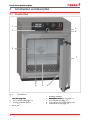
This manual describes the setup, function, transport, operation and maintenance of universal
ovens UN
PLUS
/UF
PLUS
/UF
PLUS
PLUS
,
sterilisers SN
PLUS
/SF
PLUS
/SF
PLUS
PLUS
and incubators IN
PLUS
/IF
PLUS
/IF
PLUS
PLUS
. It is intended for use
by trained personnel of the owner, who have the task of operating and/or maintaining the
respective appliance.
If you are asked to work on the appliance, read this manual carefully before starting. Familiar-
ise yourself with the safety regulations. Only perform work that is described in this manual. If
there is something you do not understand, or certain information is missing, ask your superior
or contact the manufacturer. Do not do anything without authorisation.
Versions
The appliances are available in different configurations and sizes. If specific equipment fea-
tures or functions are available only for certain configurations, this is indicated at the relevant
points in this manual.
The functions described in this manual refer to the latest firmware version.
Due to individual configurations and sizes, illustrations in this manual may be slightly different
from the actual appearance. Function and operation are identical.
Other documents that have to be observed:
►
For operation of the appliance with MEMMERT
AtmoCONTROL, observe the respective
software manual
►
For service and repair (see page 55), please refer to the separate service manual
Storage and forwarding
This instruction manual belongs with the appliance and should always be stored where
persons working on the appliance have access to it. It is the responsibility of the owner to
ensure that persons who are working or will work on the appliance are informed as to the
whereabouts of this instruction manual. We recommend that it is always stored in a protected
location close to the appliance. Make sure that the instruction manual is not damaged by heat
or humidity. If the appliance is sold on or transported and then set up again at a different
location, the operating instructions must go with it.
You will find the current version of our operating manual as pdf file if you go to
www.memmert.com/de/service/downloads/bedienungsanleitung/.

4
Contents
1. For your Safety 6
1.1 Terms and signs used
...........................................................................................................
6
1.2 Product safety and dangers
................................................................................................
7
1.3 Requirements of the operating personnel
..........................................................................
7
1.4 Responsibility of the owner
.................................................................................................
1.4 Responsibility of the owner .................................................................................................1.4 Responsibility of the owner
8
1.5 Intended use
........................................................................................................................
1.5 Intended use ........................................................................................................................1.5 Intended use
8
1.6 Changes and alterations
......................................................................................................
9
1.7 Behaviour in case of malfunctions and irregularities
..........................................................
9
1.8 Switching off the appliance in an emergency
....................................................................
1.8 Switching off the appliance in an emergency ....................................................................1.8 Switching off the appliance in an emergency
9
2. Construction and description 10
2.1 Construction
......................................................................................................................
10
2.2 Function
.............................................................................................................................
11
2.3 Material
..............................................................................................................................
11
2.4 Electrical equipment
..........................................................................................................
11
2.5 Connections and interfaces
...............................................................................................
12
2.6 Designation (nameplate)
...................................................................................................
13
2.7 Technical data
....................................................................................................................
14
2.8 Applied directives and standards
......................................................................................
15
2.9 Declaration of conformity
.................................................................................................
2.9 Declaration of conformity .................................................................................................2.9 Declaration of conformity
15
2.10 Ambient conditions
...........................................................................................................
16
2.11 Scope of delivery
...............................................................................................................
2.11 Scope of delivery ...............................................................................................................2.11 Scope of delivery
16
2.12 Optional accessories
..........................................................................................................
16
3. Delivery, transport and setting up 17
3.1 For your Safety
...................................................................................................................
3.1 For your Safety ...................................................................................................................3.1 For your Safety
17
3.2 Delivery
..............................................................................................................................
3.2 Delivery ..............................................................................................................................3.2 Delivery
18
3.3 Transport
............................................................................................................................
18
3.4 Unpacking
.........................................................................................................................
18
3.5 Storage after delivery
........................................................................................................
3.5 Storage after delivery ........................................................................................................3.5 Storage after delivery
18
3.6 Setting up
..........................................................................................................................
19
4. Putting into operation 22
4.1 Connecting the appliance
.................................................................................................
4.1 Connecting the appliance .................................................................................................4.1 Connecting the appliance
22
4.2 Switching on
......................................................................................................................
22
5. Operation and control 23
5.1 Operating personnel
..........................................................................................................
23
5.2 Opening the door
..............................................................................................................
5.2 Opening the door ..............................................................................................................5.2 Opening the door
23
5.3 Loading the appliance
.......................................................................................................
5.3 Loading the appliance .......................................................................................................5.3 Loading the appliance
24
5.4 Operating the appliance
....................................................................................................
5.4 Operating the appliance ....................................................................................................5.4 Operating the appliance
24
5.5 Temperature monitoring
..................................................................................................
31
5.6 Graph
.................................................................................................................................
35
5.7 Ending operation
...............................................................................................................
35
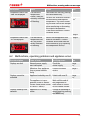
6. Malfunctions, warning and error messages 36
6.1 Warning messages of the monitoring function
................................................................
36
6.2 Malfunctions, operating problems and appliance errors
................................................
37
6.3 Power failure
......................................................................................................................
6.3 Power failure ......................................................................................................................6.3 Power failure
39
Contents

5
Contents
7. Menu mode 40
7.1 Overview
............................................................................................................................
7.1 Overview ............................................................................................................................7.1 Overview
40
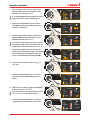
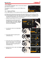
7.2 Basic operation in menu mode using the example of language selection
.......................
41
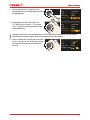
7.3 Setup
..................................................................................................................................
42
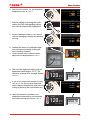
7.4 Date and Time
...................................................................................................................
7.4 Date and Time ...................................................................................................................7.4 Date and Time
46
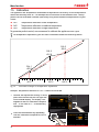
7.5 Calibration
.........................................................................................................................
48
7.6 Programme
........................................................................................................................
7.6 Programme ........................................................................................................................7.6 Programme
50
7.7 Sound
................................................................................................................................
51
7.8 Protocol
.............................................................................................................................
52
7.9 User ID
...............................................................................................................................
53
8. Sterilisers SF
PLUS
/SN
PLUS
/SN
PLUS
PLUS 54
8.1 Intended use
......................................................................................................................
8.1 Intended use ......................................................................................................................8.1 Intended use
54
8.2 Note in accordance with Medical Devices Directive
........................................................
54
8.3 Guidelines for sterilisation
.................................................................................................
54
9. Maintenance and service 55
9.1 Cleaning
.............................................................................................................................
55
9.2 Regular maintenance
.........................................................................................................
55
9.3 Repairs and service
............................................................................................................
9.3 Repairs and service ............................................................................................................9.3 Repairs and service
55
10. Storage and disposal 56
10.1 Storage
..............................................................................................................................
10.1 Storage ..............................................................................................................................10.1 Storage
56
10.2 Disposal
.............................................................................................................................
56
Index 57

6
Safety regulations
1.
For your Safety
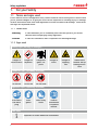
1.1
Terms and signs used
In this manual and on the appliance itself, certain common terms and signs are used to warn
you of possible dangers or to give you hints that are important in avoiding injury or damage.
Observe and follow these hints and regulations to avoid accidents and damage. These terms
and signs are explained below.
1.1.1
Terms used
"Warning"
is used whenever you or somebody else could be injured if you do not
observe the accompanying safety regulation.
"Caution"
is used for information that is important for avoiding damage.
1.1.2
Signs used
Warning signs (warning of a danger)
Danger of
electrocution
Danger of
explosion
Dangerous
gases / va-
pours
Danger of
burns
Danger of
toppling
over
Hazard area!
Observe the op-
erating instruc-
tions
Prohibition signs (forbidding an action)
Do not lift
Do not tilt
Do not enter
Regulation signs (stipulating an action)
Disconnect
the mains
plug
Wear
gloves
Wear safety
boots
Observe
information
in separate
manual
Other icons
Important or useful additional information

7
Safety regulations
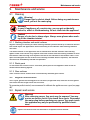
1.2
Product safety and
dangers
The appliances described in this manual are technically sophisticated, manufactured using
high-quality materials and subject to many hours of testing in the factory. They contain the
latest technology and comply with recognised technical safety regulations. However, there are
still risks involved, even when the appliances are used as intended. These are described below.
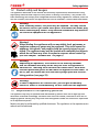
Warning!
After removing covers, live parts may be exposed. You may receive
an electric shock if you touch these parts. Disconnect the mains plug
before removing any covers. Only electrical technicians may work on
the electrical equipment of the appliances.
Warning!
When loading the appliance with an unsuitable load, poisonous or
explosive vapours or gases may be produced. This could cause the
appliance to explode, and people could be severely injured or poi-
soned. The appliance may only be loaded with materials/test objects
which do not form any toxic or explosive vapours when heated up
(see also chapter “Intended use” on page 8).
Warning!
Depending on operation, the surfaces in the working chamber
and the chamber load may still be very hot after the appliance is
switched off. Touching these surfaces can cause burns. Wear heat-
resistant protective gloves or wait until the appliance cools down. To
do so, pull the handle bar until the door springs open into its venti-
lating position (see page 23).
Warning!
In case of appliances of a certain size, you can get accidentally
locked in, which is life-threatening. Do not climb into the appliance!
1.3
Requirements of the
operating personnel
The appliance may only be operated and maintained by persons who are of legal age and
have been instructed accordingly. Personnel who are to be trained, instructed or who are un-
dergoing general training may only work with the appliance under the continuous supervision
of an experienced person.
Repairs may only be performed by qualified electricians. The regulations in the separate service
manual must be observed.

8
Safety regulations
1.4
Responsibility of the owner
The owner of the appliance
►
is responsible for the flawless condition of the appliance and for its proper operation in
accordance with its intended use (see page 8);
►
is responsible for ensuring that persons who are to operate or service the appliance are
qualified to do this, have been instructed accordingly and are familiar with the operating
instructions at hand;
►
must know about the applicable guidelines, requirements and operational safety regula-
tions, and train staff accordingly;
►
is responsible for ensuring that unauthorised persons have no access to the appliance;
►
is responsible for ensuring that the maintenance plan is adhered to and that maintenance
work is carried out properly (see page 55);
►
has to ensure that the appliance and its surroundings are kept clean and tidy, for example
through corresponding instructions and inspections;
►
is responsible for ensuring that personal protective clothing is worn by operating person-
nel, e.g. work clothes, safety shoes and protective gloves.
1.5
Intended use
This appliance is exclusively intended for heating up non-explosive substances and objects.
Any other use is improper, and may result in hazards and damage.
The appliance is not
explosion-proof (does not comply with the German workplace health &
safety regulation VBG 24). The appliance may only be loaded with materials and substances
which cannot form any toxic or explosive vapours at the set temperature and which cannot
explode, burst or ignite.
The appliance may not be used for drying, vaporising and branding paints or similar materi-
als the solvents of which could form an explosive mixture when combined with air. If there
is any doubt as to the composition of materials, they must not be loaded into the appliance.
Potentially explosive gas-air mixtures must not form, neither in the working chamber nor in
the direct vicinity of the appliance.
Intended use as a
medical device
For appliances subject to the 93/42/EEC guideline (Council Directive on the approximation of
the laws of the Member States relating to medical devices), the intended use is defined as
follows:
►
For appliances of the UF
PLUS
type series: The appliance serves for heating non-sterile cloths
and covers.
►
For appliances of the IF
PLUS
type series: The appliance serves for heating non-sterile cloths
and covers, as well as for temperature control of rinsing and infusion solutions.
►
For appliances of the IN
PLUS
type series: The appliance serves for temperature control of
rinsing and infusion solutions.
►
For appliances of the SF
PLUS
type series: The appliance serves for sterilising medical material
through dry heated air at atmospheric pressure (also see page 54).

9
Safety regulations
1.6
Changes and alterations
No unauthorised changes or alterations may be made to the appliance. No parts may be
added or inserted which have not been approved by the manufacturer.
Unauthorised modifications or changes result in the CE declaration of conformity losing its
validity and the appliance must no longer be operated.
The manufacturer is not liable for any damage, danger or injuries that result from unauthor-
ised changes or alterations, or from non-observance of the regulations in this manual.
1.7
Behaviour in case of
malfunctions and irregularities
The appliance may only be used in a flawless condition. If you as the operator notice irregu-
larities, malfunctions or damage, immediately take the appliance out of service and inform
your superior.
You can find information on correcting malfunctions from page 36.
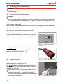
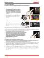
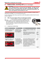
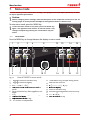
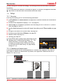
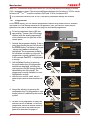
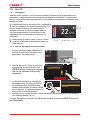
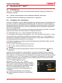
1.8
Switching off the appliance in an
emergency
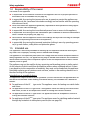
Push the On/Off switch on the control panel
( Fig. 1 ) and disconnect power plug. This
disconnects the appliance from the power
supply at all poles.
Warning!
Depending on operation,
the surfaces in the working
chamber and the chamber
load may still be very hot af-
ter the appliance is switched
off. Touching these surfaces
can cause burns. Wear heat-
resistant protective gloves
or wait until the appliance
cools down. To do so, pull
the handle bar until the
door springs open into its
ventilating position (see
page 23).
Hauptschalter
>
Zu der Typenbezeichnung gibt es momentan drei Entwurfsrichtungen,
ich kann Ihnen noch nicht sagen, ob Memmert hierzu schon eine Entscheidung
getroen hat.
Die hier gezeigt Variante, ist die von uns empfohlene Richtung.
UF 110
PLUS
ON
344.4
444 4.
TEMP
Set
°C
°C
FLAP
40%
TIMER
hd
1002
End Sept.29 22 24
FAN
%0
%
100
ALARM
max
444.4°C
auto
+
/
-
0.0K
min
444.4°C
O
O
ON
N
N
N
O
O
N
O
Manu
44.Sept
Fig. 1
Switch off the appliance by pressing the On/
Off switch

10
Construction and description
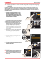
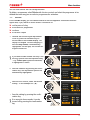
2.
Construction and description
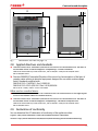
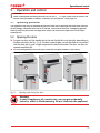
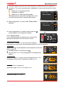
2.1
Construction
1
2
3
4 5 6
1
7
8
9
Fig. 2
Construction
1
ControlCOCKPIT with capacitive function
keys (see page 25)
ControlCOCKPIT with capacitive function
keys (see page 25)
ControlCOCKPIT with capacitive function
2
On/Off switch (see page 22)
keys (see page 25)
On/Off switch (see page 22)
keys (see page 25)
3
Working chamber fan (for
On/Off switch (see page 22)
Working chamber fan (for
On/Off switch (see page 22)
UF/IF/SF appliances only)
Working chamber fan (for
UF/IF/SF appliances only)
Working chamber fan (for
4
Steel grid
UF/IF/SF appliances only)
Steel grid
UF/IF/SF appliances only)
5
Working chamber
6
Nameplate (covered, see page 13)
Working chamber
Nameplate (covered, see page 13)
Working chamber
7
Door handle (see page 23)
Nameplate (covered, see page 13)
Door handle (see page 23)
Nameplate (covered, see page 13)
8
Turn control with confirmation key
Door handle (see page 23)
Turn control with confirmation key
Door handle (see page 23)
9
USB interface (see page 12)
Turn control with confirmation key
USB interface (see page 12)
Turn control with confirmation key

11
Construction and description
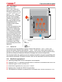
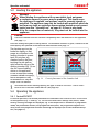
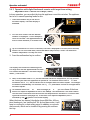
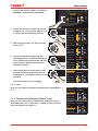
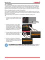
2.2
Function
Appliances of the
UN
PLUS
, SN
PLUS
and IN
PLUS
type series feature natural
circulation (convection). For
the UF
PLUS
, SF
PLUS
and IF
PLUS
type series, air is circulated
by a fan at the working
chamber rear panel (Fig. 3 ,
No. 1). It increases the air
flow and provides stronger
horizontal forced air
circulation than natural
convection.
In both the convection and
fan ventilated appliances,
supply air (2) is preheated
in a pre-heating chamber
(3). Through the ventilation
slits in the side panel of the
working chamber, the pre-
heated air is introduced into
the interior of the chamber.
The supply and exhaust air
(5) volume (air change) is
controlled by the air flap
(4) on the rear panel of the
appliance.
2.3
Material
For the outer housing, MEMMERT deploys stainless steel (Mat.No. 1.4016 – ASTM 430)
and for the interior, stainless steel (Mat.No. 1.4301 – ASTM 304) is used, which stands out
through its high stability, optimal hygienic properties and corrosion-resistance towards many
(but not all!) chemical compounds (caution for example with chlorine compounds).
The chamber load for the appliance must be carefully checked for chemical compatibility with
the materials mentioned. A material resistance table can be requested from the manufacturer.
2.4
Electrical equipment
►
Operating voltage and current consumption: See nameplate
►
Protection class I, i.e. operating insulation with PE conductor in accordance with EN 61010
►
Protection type IP 20 acc. to EN 60 529
►
Interference suppression acc. to EN 55011 class B
►
Appliance fuse: Fusible link 250 V/15 A quick-blow
►
The temperature controller is protected with a miniature fuse 100 mA (160 mA at 115 V)
4
4
4
4
1
1
2
5
3
3
3
Fig. 3
Function
1
Fan
2
Fresh air
3
Pre-heating chamber
4
Air flap
Pre-heating chamber
Air flap
Pre-heating chamber
5
Exhaust air
Air flap
Exhaust air
Air flap

12
Construction and description
2.5
Connections and
interfaces
2.5.1
Electrical connection
This appliance is intended for operation on an electrical power system with a system imped-
ance Z
max
of a maximum of 0.292 ohm at the point of transfer (service line). The operator
max
of a maximum of 0.292 ohm at the point of transfer (service line). The operator
max
must ensure that the appliance is operated only on an electrical power system that meets
these requirements. If necessary, you can ask your local energy supply company what the
system impedance is.
Observe the country-specific regulations when connecting (e.g. in Germany
DIN VDE 0100 with residual current circuit breaker).
2.5.2
Communication interfaces
The interfaces are intended for appliances which meet the requirements of IEC 60950-1.
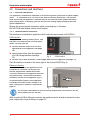
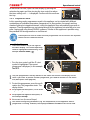
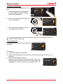
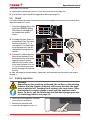
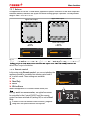
USB interface
The appliance is fitted by default with a
USB
interface in accordance with the USB specifi-
cation. This way, you can
►
transfer software stored on a USB stor-
age medium to the appliance (see page
50).
►
export protocol logs from the appliance
to a USB storage medium (see page
52).
►
transfer user ID data stored on a USB storage medium to the appliance (see page 53).
The USB interface is located on the lower right of the ControlCOCKPIT (Fig. 4 ).
Ethernet interface
Via Ethernet interface, the appliance can be
connected to a
network, so that you can
transfer programmes created with
Atmo-
CONTROL software to the appliance and read
out protocol logs. The Ethernet interface is
located on the rear of the appliance (Fig. 5 ).
For identification purposes, each appliance
connected must have its own unique IP ad-
dress. Setting the IP address is described on
page 42.
You will find a description of how to transfer programmes via Ethernet in the en-
closed
AtmoCONTROL manual.
With an optional USB to Ethernet converter, the appliance can be directly connected to a com-
puter / laptop (see Scope of delivery on page 16).
Fig. 4
USB interface
Fig. 5
Ethernet interface

13
Construction and description
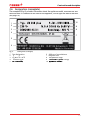
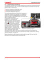
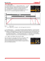
2.6 Designation ( nameplate)
The nameplate (Fig. 6) provides information about the appliance model
, manufacturer and
technical data. It is attached to the front of the appliance, on the right side behind the door
(see page 10).
Typ: UN 260 plus F.-Nr.: 0109.0088
230 V
~
14.8 A 50/60 Hz 3400 W
DIN12880-Kl.3.1 Nenntemp.: 300 °C
1
2
3
4
5
6
10
8
9
7
Fig. 6
Nameplate (example)
1
Type designation
2
Operating voltage
Type designation
Operating voltage
Type designation
3
Applied standard
Operating voltage
Applied standard
Operating voltage
4
Protection type
5
CE conformity
Protection type
CE conformity
Protection type
6
Address of manufacturer
7
Disposal note
8
Temperature range
9
Connection / power ratings
Temperature range
Connection / power ratings
Temperature range
10
Appliance number
Connection / power ratings
Appliance number
Connection / power ratings

14
Construction and description
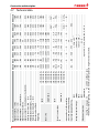
2.7
Technical data
Appliance size 30 55 75 110 160 260 450 750
Appliance width D
1
[mm]
585
585
585
745
745
824
1224
1224
Appliance height E
1
[mm]
707
787
947
867
1107
1186
1247
1726
Appliance depth G
1
(footprint) [mm]
434
514
514
584
584
684
784
784
Depth of door lock [mm]
56
Appliance depth F
1
(including door handle) [mm]
490
570
570
640
640
740
840
840
Working chamber width A
1
[mm]
400
400
400
560
560
640
1040
1040
Working chamber height B
1
[mm]
320
400
560
480
720
800
720
1200
Working chamber depth C
1
[mm]
250
330
330
400
400
500
600
600
Chamber volume [litres]
32
53
74
108
161
256
449
749
Weight [kg]
48
57
66
78
96
110
170
217
Power [W]
IN/IF
115 V, 50/60 Hz
1600
850
1100
1100
1100
1100
1500
1800
230 V, 50/60 Hz
1600
1000
1250
1400
1600
1700
1800
2000
UN/UF/SN/SF
230 V, 50/60 Hz
1600
2000
2500
2800
3200
3400
-
-
115 V, 50/60 Hz
1600
1700
2200
2200
2200
2200
-
-
400 V, 50/60 Hz
–
5800
2
7000
2
Current consumption
[A]
IN/IF
230 V, 50/60 Hz
7,0
4,3
5,4
6,1
7,0
7,4
7,8
8,7
115 V, 50/60 Hz
13,9
7,4
9,6
9,6
9,6
9,6
13,0
15,7
UN/UF/SN/SF
230 V, 50/60 Hz
7,0
8,7
10,9
12,2
13,9
14,8
-
-
115 V, 50/60 Hz
13,9
14,8
19,1
19,1
19,1
19,1
-
-
400 V, 50/60 Hz
–
3 x 8,4
2
3 x 10,2
2
max. number of sliding shelves
3
4
6
5
8
9
8
14
max. load per sliding shelve [kg]
30
max. load per appliance [kg]
60
80
120
175
210
300
Setting temperature range
IN/IF
+20 to +80 °C
3
UN/UF
+20 to +300 °C
3
SN/SF
+20 to +250 °C
3
Adjustment precision
IN/IF
0.1 K
UN/UF/SN/SF
up to 100 °C: 0.1 K, above 100 °C: 0.5 K
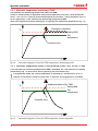
1
See Fig. 7 on page 15
2
3 x 230 V without zero
3
With the interior lighting on, the minimum temperature might not be reached.

15
Construction and description
D
A
G
F
C
56
E
B
Fig. 7
Dimensions (see table on page 14)
2.8
Applied directives and standards
►
Directive 2004/108/EC amended (Directive of the council on harmonisation of the laws of
the member states on electromagnetic compatibility). Fulfilled standards:
DIN EN 61326:2004-05, EN 61326:1997, EN 61326/A1:1998, EN 61326/A2:2001
EN 61326/A2:2003
►
Directive 2006/95/EC amended (Directive of the council on harmonisation of the laws of
member states relating to electrical equipment designed for use within certain voltage
limits). Standards complied with:
DIN EN 61 010-1 (VDE 0411 Part 1):2002-08
DIN EN 61 010-2-010 (VDE 0411 Part 2-010):2004-06
EN 61 010-1:2001, EN 61 010-2-010:2003
When used as a medical device
►
Directive 93/42/EEC (Directive of the Commission on the harmonisation of the legal regula-
tions of the member states on medical devices)
►
Directive 2004/108/EC amended (Directive of the council on harmonisation of the laws of
the member states on electromagnetic compatibility). Standards complied with:
DIN EN 61326:2004-05, EN 61326:1997, EN 61326/A1:1998, EN 61326/A2:2001
EN 61326/A2:2003
2.9
Declaration of conformity
You can download the EC declaration of conformity of the appliance online:
English: http://www.memmert.com/en/service/downloads/ce-statement/
German: http://www.memmert.com/de/service/downloads/eg-konformitaetserklaerung/

16
Construction and description
2.10
Ambient conditions
►
The appliance may only be used in enclosed rooms and under the following ambient
conditions:
Ambient temperature
+5
º
C to +40
º
C
Humidity rh
max. 80 %, non-condensing
Overvoltage category
II
Pollution degree
2
Altitude of installation
max. 2,000 m above sea level
►
The appliance may not be used in areas where there is a risk of explosion. The ambient air
must not contain any explosive dusts, gases, vapours or gas-air mixtures. The appliance is
not explosion-proof.
►
Heavy dust production or aggressive vapours in the vicinity of the appliance could lead to
sedimentation in the interior and, as a consequence, could result in short circuits or dam-
age to electrical parts. For this reason, sufficient measures to prevent large clouds of dust
or aggressive vapours from developing should be taken.
2.11
Scope of delivery
►
Power cable
►
Tilt protection
►
One or two sliding steel grids (load capacity 30 kg each)
►
USB storage medium with software and
AtmoCONTROL manual
►
The operating instructions at hand
►
Calibration certificate
2.12
Optional
accessories
►
USB to Ethernet converter (Fig. 8). Makes it
possible to connect the appliance's
network interface (see page 12) to the
USB port of a computer / laptop.
►
Reinforced, sliding steel grids with a load
capacity of 60 kg each (for appliance size
110 and larger)
Fig. 8
Converter USB to Ethernet

17
Delivery, transport and setting up
3.
Delivery,
transport and
setting up
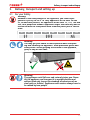
3.1
For your Safety
Warning!
Because of the heavy weight of the appliance, you could injure
yourself if you try to lift it. To
carry appliances of the sizes 30 and
55, at least two persons, for appliances of the sizes 75, 110, 160 and
260, four people are needed. Appliances larger than that may not be
carried but must be transported with a manual pallet jack or forklift
truck.
30 55 75 110 160 260 450 750
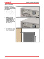
Warning!
You may get your hands or feet squashed when transport-
ing and installing the appliance. Wear protective gloves and
safety boots. When grasping the bottom of the appliance,
grasp it only on the sides:
Warning!
The appliance could fall over and seriously injure you. Never
tilt the appliance and transport it in upright position and
without load only (except for standard accessories such as
steel grids or shelves). Appliances with castors always have to
be moved by two people.

18
Delivery, transport and setting up
3.2
Delivery
The appliance is packed in cardboard and is delivered on a wooden palette.
3.3
Transport
The appliance can be transported in three ways:
►
With a
forklift truck; move the forks of the truck entirely under the pallet
►
On a manual pallet jack
►
On its own castors, in case of the corresponding configuration, for which the catch on the
(front) castors must be released
3.4
Unpacking
To avoid damage, do not unpack the appliance until you reach the installation site.
Remove the cardboard packaging by pulling it upwards or carefully cutting along an edge.
3.4.1
Checking for completeness and
transport damage
►
Check the delivery note to ensure that the delivery is complete.
►
Check the appliance for damage.
If you notice deviations from the delivery note, damage or irregularities, do not put the appli-
ance into operation but inform the haulage company and the manufacturer.
3.4.2
Disposing of
packaging material
Dispose of the packaging material (cardboard, wood, foil) in accordance with the applicable
disposal regulations for the respective material in your country.
3.5
Storage after delivery
If the appliance is first to be stored after delivery: Read the storage conditions from page
56.

19
Delivery, transport and setting up
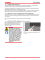
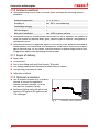
3.6
Setting up
Warning!
Due to its centre of gravity, the appliance can fall over to the front
and injure you or other people. Always attach the appliance to a wall
with the tilt protection (see page 21). If this cannot be done due
to space problems, do not operate the appliance and do not open
the door. Contact the Memmert service team (see page 2).
3.6.1
Prerequisites
The
installation site must be flat and horizontal and must be able to reliably bear the weight
of the appliance (see "Technical data" on page 14). Do not place the appliance on a flam-
mable surface.
Depending on the model (see nameplate), a 230 V, 115 V or 400 V power connection must be
available at the installation site.
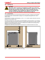
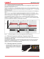
The distance between the wall and the rear of the appliance must be at least 15 cm. The clear-
ance from the ceiling must not be less than 20 cm and the side clearance from walls or nearby
appliances must not be less than 5 cm (Fig. 9). Sufficient air circulation in the vicinity of the
appliance must be guaranteed at all times.
For appliances with castors, these need to be positioned in forward direction at all times.
≥ 5 cm ≥ 5 cm ≥ 15 cm
≥ 20 cm
Fig. 9
Minimum clearance from walls and ceiling

20
Delivery, transport and setting up
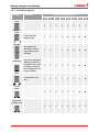
3.6.2
Installation options
Setting up Comments Suitable for appliance size ...
30 55 75 110 160 260 450 750
Floor
Table
Check the load
capacity first
Stacked
two appliances
maximum; mount-
ing material (feet)
provided
Wall
mounting
Separately packaged
fastening material is
included in the scope
of delivery. Observe
the assembly instruc-
tions provided.
Base
with/without cas-
tors
Castor
frame
Height ad-
justable feet
Seite wird geladen ...
Seite wird geladen ...
Seite wird geladen ...
Seite wird geladen ...
Seite wird geladen ...
Seite wird geladen ...
Seite wird geladen ...
Seite wird geladen ...
Seite wird geladen ...
Seite wird geladen ...
Seite wird geladen ...
Seite wird geladen ...
Seite wird geladen ...
Seite wird geladen ...
Seite wird geladen ...
Seite wird geladen ...
Seite wird geladen ...
Seite wird geladen ...
Seite wird geladen ...
Seite wird geladen ...
Seite wird geladen ...
Seite wird geladen ...
Seite wird geladen ...
Seite wird geladen ...
Seite wird geladen ...
Seite wird geladen ...
Seite wird geladen ...
Seite wird geladen ...
Seite wird geladen ...
Seite wird geladen ...
Seite wird geladen ...
Seite wird geladen ...
Seite wird geladen ...
Seite wird geladen ...
Seite wird geladen ...
Seite wird geladen ...
Seite wird geladen ...
Seite wird geladen ...
Seite wird geladen ...
Seite wird geladen ...
-
 1
1
-
 2
2
-
 3
3
-
 4
4
-
 5
5
-
 6
6
-
 7
7
-
 8
8
-
 9
9
-
 10
10
-
 11
11
-
 12
12
-
 13
13
-
 14
14
-
 15
15
-
 16
16
-
 17
17
-
 18
18
-
 19
19
-
 20
20
-
 21
21
-
 22
22
-
 23
23
-
 24
24
-
 25
25
-
 26
26
-
 27
27
-
 28
28
-
 29
29
-
 30
30
-
 31
31
-
 32
32
-
 33
33
-
 34
34
-
 35
35
-
 36
36
-
 37
37
-
 38
38
-
 39
39
-
 40
40
-
 41
41
-
 42
42
-
 43
43
-
 44
44
-
 45
45
-
 46
46
-
 47
47
-
 48
48
-
 49
49
-
 50
50
-
 51
51
-
 52
52
-
 53
53
-
 54
54
-
 55
55
-
 56
56
-
 57
57
-
 58
58
-
 59
59
-
 60
60


Memmert UF PLUS Operating Instructions Manual
- Typ
- Operating Instructions Manual
in anderen Sprachen
- English: Memmert UF PLUS
Verwandte Artikel

Andere Dokumente
-
Binder FED 400 Bedienungsanleitung
-
-
Binder B 28 Bedienungsanleitung
-
CONSTRUCTA CZ53XXB1X6 Spezifikation
-
Parkside PBK 4 A1 Translation Of The Original Instructions
-
-
FLORABEST 273489 Bedienungsanleitung
-
Parkside PFDS 33 A1 Original Instructions Manual
-
-
Vestfrost VTS098 Benutzerhandbuch