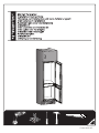
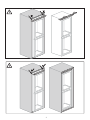
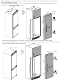
Blomberg BRFB1051FFBIN Installation Diagram
- Typ
- Installation Diagram

5728410000-AP
Seite wird geladen ...

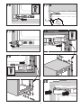
2
64
2.51”
34
1.33”
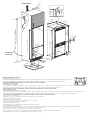
200 cm
2
min 200 cm
2
min.75 mm
min.10 mm
min.30 mm
629.6
24.78”
999.8
39.36”
16
0.62”
min.
1.96”
min.
11.8”
min.
7.87”
min.
7.87”
min.
0.39”

3
90
o
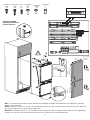
1
1
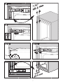
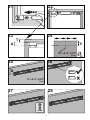
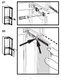
Not: 2-3 numara ile gösterilen montaj adımında üst bağlantı plastiğini kaydırabilmek için bağlantının yapıldığı
vidaları tam sıkmayınız.
Note: Installation step for 2, screws for connecting top plastic rpart should not be screwed very hard, because
of moving the plastic part easily left or right side.
Hinweis: Installationsschritt 2: Die Schrauben zum Fixieren des Kunststoffteils sollten nicht zu fest angezogen
werden, da sich das Kunststoffteil ansonsten nach links oder rechts verschieben kann.
2
3
4
S
For 19 mm
furniture
thickness
2nd Type Wood
(2TW)
X16
1st Type Metric
(1TM)
X5
2st Type Metric
(2TM)
X5
Sheet
(S)
X12
1st Type Wood
(1TW)
X12
* Spares Included
* Ersatzteile inklusive
* Pièces incluses
590 mm
23.22”
1100 mm
43.3”
718 mm
28.27”
Takoz / Wedge
X1
W2
W2
Seite wird geladen ...

For 19 mm
furniture
thickness
590 mm
23.22”
1100 mm
718 mm
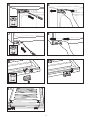
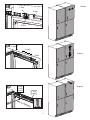
When installing a twin non-ice unit adjacent to the ice maker unit model , same filler strip should be used to align
furniture cabinet for each model .
If the furniture cabinet dimension is 71,6”-72”/1818-1828 mm, long filler strip (5917500100) should be used.
Furnitre cover dimensions are shown in picture.
When installing a singular only non –ice unit , short filler strip should be used to align furniture cabinet.
If the furniture cabinet dimension is 70,43”-74,80”(1789-1900 mm), short filler strip (4918140100) should be used.
Furnitre cover dimensions are shown in picture.
5
70-70,39” /1778-1788 mm
For 19 mm
furniture
thickness
590 mm
23.22”
1140 mm
718 mm
71.6 - 72 ” /1818 - 1828 mm

(2TM)
(2TM)
5 6
7 8
9
11
10
(1TM)
6

40.5 mm
7
40.5 mm
(1TW)
12
13
40.5 mm
40.5 mm
15
14-b14-a
1.59”
1.59”

8
40.5 mm
1,59”
20
17-b
1,59”
40.5 mm
(1TW)
19
16
17-a
40.5 mm
(S)
40.5 mm
(S)
18

9
(2 TW)
22
27 28
23 24
21
25
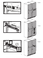
A
T
26
X = A+T- 0,23”
(6mm)
X = A+T- 0,23”
(6mm)

10
29
30
Seite wird geladen ...

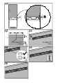
12
37
38

13
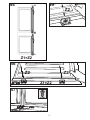
Y-axis
X-axis
Z-axis
38
Y-axis
X-axis
Z-axis
39
X-axis
Z-axis
Y-axis
Y-axis
X-axis
Z-axis
Y-axis
Z-axis
(2 TW)
40

14
Y-axis
X-axis
Z-axis
41
42
X-axis
Z-axis
Y-axis
43
Y-axis
X-axis
Z-axis
Y-axis
X-axis
Z-axis
Y-axis
Z-axis
(2 TW)

15
(1TW)
47
46
45
Z2 Z2
Z2
Z1=Z2
44
Z1=Z2
Z1
Z2
Z1
Z2

16
-
 1
1
-
 2
2
-
 3
3
-
 4
4
-
 5
5
-
 6
6
-
 7
7
-
 8
8
-
 9
9
-
 10
10
-
 11
11
-
 12
12
-
 13
13
-
 14
14
-
 15
15
-
 16
16
-
 17
17


Blomberg BRFB1051FFBIN Installation Diagram
- Typ
- Installation Diagram
in anderen Sprachen
- English: Blomberg BRFB1051FFBIN
- Türkçe: Blomberg BRFB1051FFBIN
Verwandte Artikel

Andere Dokumente
-
Teka TKI2 300 EU Installationsanleitung
-
Beko K54285B Benutzerhandbuch
-
-
Beko S54210B Benutzerhandbuch
-
-
Eneo VPT-601 RAL7035 Installation & Operating Manual
-
 Wolkenstein KGK 180 A Series Benutzerhandbuch
-
Philips SRU5020P/02 Benutzerhandbuch
-
Kollmorgen MKD-N240007 Product Safety Manual
-
Nexo R2 Benutzerhandbuch
