CARLO GAVAZZI RSGD4070E0VX310C Bedienungsanleitung
- Typ
- Bedienungsanleitung

RSGD
Troubleshooting 2
Problembehebung 7
Ricerca guasti 13
Défauts 19
Soluciones 24
Fejlfinding 30
故障排除
35
Поиск и устранение неисправностей 40

Troubleshooting EN
Carlo Gavazzi RSGD Troubleshooting Guide – Rev 1.0 2
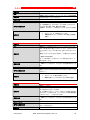
LED Status Indications
State Supply
(green LED) Ramp/Bypass
(yellow LED) Alarm
(red LED) Manual
(yellow LED)
Idle ON OFF OFF OFF/ON
Ramping ON Flashing OFF OFF/ON
Bypass ON OFF OFF OFF/ON
Alarm (Auto-recovery) ON OFF Flashing OFF
Alarm (Manual recovery) ON OFF Flashing ON
Internal fault ON OFF OFF OFF/ON
Relay status indication
State Supply
(green LED)
Relay contact position
RSGD 45mm RSGD 75mm
Alarm
(11, 12)
Bypass
(21, 24)
Alarm
(11, 12, 14)
Bypass
(21, 22, 24)
Run
(31, 34)
Idle
ON
Closed
Open
11, 12
21, 22
Open
Ramping
ON
Closed
Open
11, 12
21, 22
Closed
Bypass
ON
Closed
Closed
11, 12
21, 24
Closed
Alarm (auto
-
recovery) ON Open Open 11, 14 21, 22 Open
Alarm (manual
recovery) ON Open Open 11, 14 21, 22 Open
Internal fault
ON
Open
Open
11, 14
21, 22
Open
Alarms
The RSGD includes a number of diagnostics and protection features each of which is signalled
through a flashing sequence on the red LED. After each flashing cycle, there is a delay (OFF time) on
the red LED of 1.5sec before the next cycle starts. During the alarm recovery period, the red LED will
flash at twice the frequency to indicate that the RSGD is in recovery mode.

Troubleshooting EN
Carlo Gavazzi RSGD Troubleshooting Guide – Rev 1.0 3
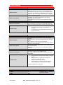
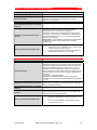
Number of flashes 2
Alarm Wrong phase sequence
Alarm description
If the connection to the soft starter is not done in the correct
sequence (L1, L2, L3), the RSGD will trigger the wrong phase
sequence alarm and the motor will not be started.
Alarm recovery period N/A
Consecutive alarms for hard reset 1
Action to recover alarm
User intervention is required to change the wiring sequence to
recover alarm.
Note: the phase sequence monitoring can be disabled. To disable
the alarm, press the Test/Reset button for 10 seconds when the
RSGD is in IDLE state. The yellow LED will turn ON.
ATTENTION: in this mode, if the wiring is not in the correct
sequence, the motor will rotate in the reverse direction.
Troubleshooting
Check that wiring on L1, L2, L3 is in the correct
sequence.
If you need to reverse the motor, make sure that the
phase sequence LED is ON (phase sequence protection
disabled).
Number of flashes 3
Alarm Line voltage out of range
Alarm description
At every power-up the RSGD automatically detects the supply
voltage level and determines whether it is working on a 220, 400,
480* or 600* V supply. The under- or over- voltage alarm level is
then set at a level of -20% and + 20% (from the measured supply
voltage level) respectively.
If the supply voltage level is out of these limits for more than 5
seconds then the line voltage out of range alarm will be triggered.
* Applies to RSGD60 models.
Note: for RSGD60 over-voltage alarm level (for the case of a
600V supply) is 675V (600V + 11%).
Alarm recovery period
5 minutes
(If manual reset mode is applied, alarm can be reset by pressing
the Test/ Reset button).
Consecutive alarms for hard reset 4
Action to recover alarm The alarm will self-recover (in auto-recovery mode) after 5
minutes from when the supply voltage is within limits.
Troubleshooting
Check supply voltage level across L1, L2, L3 terminals.
Make sure that you are not using a RSGD40 model on a
supply voltage > 440 VAC.

Troubleshooting EN
Carlo Gavazzi RSGD Troubleshooting Guide – Rev 1.0 4
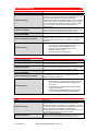
Number of flashes 4
Alarm Phase loss (motor side)
Alarm description
If any of the phases on the load (motor) side becomes open the
RSGD will trip after 5 seconds to protect the motor from running/
starting on 2 phases.
Note: this alarm will also be triggered when a current unbalance of
> 20% is detected on any of the three line currents for a minimum
of 5 secs. Additionally if a SCR and/or bypass relay is open
(damaged) the same alarm will be triggered.
Alarm recovery period
5 minutes
(If manual reset mode is applied, alarm can be reset by pressing
the Test/ Reset button).
Consecutive alarms for hard reset 4
Action to recover alarm
Check connections on the output side of the soft starter and on
the motor terminals. The alarm will self-recover (in Auto-recovery
mode) after 5 minutes.
Troubleshooting
Check for any loose connections on the T1, T2, T3 side
of the soft starter.
Check for any loose connections on the motor terminals.
Check motor windings.
Number of flashes
5
Alarm Locked rotor
Alarm description If a current ≥ 8xFLC setting for 100 msec is detected, the RSGD
will issue the locked rotor alarm.
Alarm recovery period
5 minutes
(If manual reset mode is applied, alarm can be reset by pressing
the Test/ Reset button).
Consecutive alarms for hard reset 4
Action to recover alarm The alarm will self-recover (in Auto-recovery mode) after 5
minutes.
Troubleshooting
Check that FLC setting is not smaller than motor name
plate current.
Check that the RSGD model is suitably rated for the
motor.
Check motor windings resistance to check if motor is
damaged.

Troubleshooting EN
Carlo Gavazzi RSGD Troubleshooting Guide – Rev 1.0 5
Number of flashes 7
Alarm Over-temperature
Alarm description
The RSGD constantly measures the heatsink and thyristors
(SCRs) temperature. If the maximum internal temperature is
exceeded (for a minimum of 0.5 sec) an over-temperature alarm
is triggered. This condition can be triggered by too many starts
per hour, an over-load condition during starting and/or stopping or
a high surrounding temperature.
Alarm recovery period
Depends on the cooling period.
(If MANUAL reset mode is applied, alarm can be reset by
pressing the Test/ Reset button).
The RSGD will only recover if the internal temperature is within
safe limits.
Consecutive alarms for hard reset 4
Action to recover alarm
The alarm will self-recover (in Auto-recovery mode) - the recovery
period will depend on the cooling time required by RSGD. The
higher the surrounding temperature, the longer the cooling period.
Troubleshooting
Check that the specified number of starts/hr is not
exceeded.
Check that the surrounding temperature around the soft
starter is within limits.
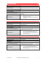
Number of flashes 8
Alarm Overload
Alarm description
The overload alarm can be triggered in case of the following
conditions:
Measured current > 1.05 x FLC during transition from ramp-up to
bypass.
High resistance (> 1000 ohm) at P1, P2 terminals.
Load current > FLC. Trip time will vary according to Trip Class 10.
Alarm recovery period
Depends on the cooling period.
(If manual reset mode is applied, alarm can be reset by pressing
the Test/ Reset button).
The RSGD will only recover if the internal temperature is within
safe limits.
Consecutive alarms for hard reset 4
Action to recover alarm
The alarm will recover automatically after 5 minutes. If manual
reset mode is enabled, press Test/Reset button.
Note: allow enough time for the motor to cool before attempting
the next start.
Troubleshooting
Check that the P1, P2 terminals are shorted (unless PTC
is used). *
Make sure that the FLC setting is according to the
current on the motor name plate.
Check for any blockages in the load.
If overload alarm occurs during ramp-up try to set a
shorter ramp-up time or increase the FLC setting.
* Applies to RSGD 75mm models only
PTC resistance - P1, P2 connection *
< 500Ω No Trip Normal running
> 1000Ω Trip Overload alarm (8 flashes) &
alarm relay activated
< 300Ω Reset
* Note: Applies to RSGD 75mm models only.

Troubleshooting EN
Carlo Gavazzi RSGD Troubleshooting Guide – Rev 1.0 6
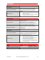
Number of flashes 9
Alarm Supply voltage unbalance
Alarm description
The RSGD measures the voltages on all the three phases and if
there is a difference of more than 20% for ≥ 5sec between any of
the phases, the RSGD will trigger the voltage unbalance alarm.
Alarm recovery period 5 minutes
Consecutive alarms for hard reset 4
Action to recover alarm The alarm will recover automatically after 5 minutes. If manual
reset mode is enabled, press Test/Reset button.
Troubleshooting
Check supply voltage level across L1, L2, L3 terminals.
Check connections on the L1, L2, L3 terminals.
Number of flashes 10
Alarm Shorted thyristor (SCR)
Alarm description In case the RSGD detects that there is a damaged (shorted)
thyristor (SCR) on any of the three phases, the soft starter will trip.
Alarm recovery period -
Consecutive alarms for hard reset 1
Action to recover alarm
Note: this alarm is not resettable and it is suggested to replace the
unit and contact a Carlo Gavazzi representative should this alarm
occur.
Troubleshooting
Check resistance across L1-T1 and L3-T3 to check for
any short.
If any of the SCRs is damaged, replace the soft starter.
Number of flashes Fully ON
Alarm Internal fault
Alarm description In case there is an internal fault in the RSGD circuitry, the Red
LED will remain continuously ON.
Alarm recovery period -
Consecutive alarms for hard reset 1
Action to recover alarm
Note: this alarm is not resettable and it is suggested to replace the
unit and contact a Carlo Gavazzi representative should this alarm
occur.
Troubleshooting
Check resistance across L1 - T1 and L3 - T3 to check for
any short.
If any of the SCRs is damaged, replace the soft starter.
Remote reset of alarms (R1, R2)*
To reset alarms via the R1-R2 terminals you need to:
Make sure that the alarm reset mode is set to MANUAL (MANUAL
LED ON).
To set the alarm reset mode to MANUAL press the Test/Reset
button for 5 seconds when the RSGD is in IDLE mode.
When RSGD is in alarm mode, short the terminals R1, R2 for 1
second. This will clear the alarm and RSGD will go to IDLE state.
Note: do not apply voltage on R1, R2 terminals as this might
damage the soft starter.

Problembehebung DE
Carlo Gavazzi RSGD Troubleshooting Guide – Rev 1.0 7
Status-LED-Anzeigen
Zustand Spannungs-
versorgung
(Grüne LED)
Rampe/Über-
brückung
(Gelbe LED)
Alarm
(Rote LED) Manuell
(Gelbe LED)
Leerlaufzustand Ein AUS AUS AUS/Ein
Anlaufzustand Ein Blinken AUS AUS/Ein
Überbrückungszustand Ein AUS AUS AUS/Ein
Automatische
Alarmrücksetzung Ein AUS Blinken AUS
Manuelle
Alarmrücksetzung Ein AUS Blinken Ein
Interner Fehler Ein AUS AUS AUS/Ein
Relais Zustandsanzeigen
Zustand
Spannungs-
versorgung
(Grüne LED)
Position der Relaiskontakte
RSGD 45mm
RSGD 75mm
Alarm
(11, 12)
Überbrückung
(21, 24)
Alarm
(11, 12,
14)
Überbrückung
(21, 22, 24)
BETRIEB
(31, 34)
Leerlaufzustand Ein Geschlossen Offen 11, 12 21, 22 Offen
Anlaufzustand Ein Geschlossen Offen 11, 12 21, 22 Geschlossen
Überbrückungszustand Ein Geschlossen Geschlossen 11, 12 21, 24 Geschlossen
A u t o m a t i s c h e
Alarmrücksetzung Ein Offen Offen 11, 14 21, 22 Offen
M a n u e l l e
Alarmrücksetzung Ein Offen Offen 11, 14 21, 22 Offen
Interner Fehler Ein Offen Offen 11, 14 21, 22 Offen
Alarme
Das RSGD ist mit verschiedenen Diagnose- und Schutzfunktionen ausgestattet. Alle diese Funktionen werden
mithilfe einer Blinksequenz der roten LED signalisiert.

Problembehebung DE
Carlo Gavazzi RSGD Troubleshooting Guide – Rev 1.0 8
Anzahl der Blinksignale 2
Alarm Falsche Phasenreihenfolge
Alarmbeschreibung
Wenn der Netzanschluss am Sanftstartgerät nicht in der richtigen
Reihenfolge (L1, L2, L3) vorgenommen wurde, löst das RSGD
den Alarm für falsche Phasenreihenfolge aus, und der Motor wird
nicht gestartet.
Alarmerholungsphase
n.v.
Aufeinanderfolgende Alarme für
hartes RÜCKSETZEN 1
Aktion zur Beseitigung des Alarms
In diesem Fall ist ein Eingriff durch den Anwender erforderlich, um
die Beschaltung zu korrigieren und den Alarm zu beseitigen.
Hinweis: kann die Überwachung der Phasenreihenfolge
deaktiviert werden. Drücken Sie zum Deaktivieren des Alarms die
Test-/Rücksetztaste 10 s lang, wenn sich das RSGD im
Leerlaufzustand (IDLE) befindet. Die gelbe LED leuchtet auf.
ACHTUNG: Wenn in diesem Modus die Beschaltung fehlerhaft
ist, rotiert der Motor in umgekehrter Richtung.
Problembehebung
Überprüfen Sie, ob L1, L2 und L3 in der richtigen
Reihenfolge verkabelt wurden.
Wenn Sie die Motorrichtung umkehren müssen, stellen
Sie sicher, dass die LED für die Phasenreihenfolge
EINgeschaltet ist (Phasenfolgenschutz deaktiviert).
Anzahl der Blinksignale
3
Alarm Netzspannung außerhalb des Bereichs
Alarmbeschreibung
Bei jedem Einschalten ermittelt das RSGD automatisch die
Versorgungsspannung und legt fest, ob es mit 220, 400, 480*
oder 600* V arbeitet. Der Unter-oder Überspannungsalarm wird
dann auf –20 % und +20 % unter bzw. über der gemessenen
Versorgungsspannung eingestellt.
Wenn die Versorgungsspannung länger als 5 Sekunden
außerhalb dieser Grenzen liegt, wird der Alarm „Netzspannung
außerhalb des Bereichs“ ausgelöst.
* Gilt für RSGD60-Modelle.
Hinweis: Beim RSGD60 liegt die Überspannungsalarmgrenze (bei
600-V-Versorgung) bei 675 V (600 V + 11 %).
Alarmerholungsphase
5 Minuten
(Wenn der manuelle Rücksetzmodus aktiviert ist, kann der Alarm
durch Drücken der Test-/Rücksetztaste beseitigt werden).
Aufeinanderfolgende Alarme für
hartes RÜCKSETZEN 4
Aktion zur Beseitigung des Alarms
Im automatischen Erholungsmodus wird der Alarm 5 Minuten,
nachdem die Versorgungsspannung wieder innerhalb der
Grenzwerte liegt, automatisch deaktiviert.
Problembehebung
Überprüfen Sie die Versorgungsspannung zwischen den
Anschlüssen L1, L2 und L3.
Stellen Sie sicher, dass Sie kein RSGD40-Modell bei
einer Versorgungsspannung von > 440 V AC betreiben.

Problembehebung DE
Carlo Gavazzi RSGD Troubleshooting Guide – Rev 1.0 9
Anzahl der Blinksignale 4
Alarm Phasenverlust (motorseitig)
Alarmbeschreibung
Wenn eine der Phasen auf der Lastseite (Motorseite)
unterbrochen wird, löst das RSGD nach 5 Sekunden aus, um zu
verhindern, dass der Motor mit 2 Phasen läuft/startet.
Hinweis: Dieser Alarm wird ebenfalls ausgelöst, wenn mindestens
5 s lang bei einem der drei Außenleiterströme eine Unsymmetrie
> 20 % festgestellt wird. Außerdem wird dieser Alarm ausgelöst,
wenn ein Thyristor- und/oder Überbrückungsrelais offen
(beschädigt) ist.
Alarmerholungsphase
5 Minuten
(Wenn der manuelle Rücksetzmodus aktiviert ist, kann der Alarm
durch Drücken der Test-/Rücksetztaste beseitigt werden).
Aufeinanderfolgende Alarme für
hartes RÜCKSETZEN 4
Aktion zur Beseitigung des Alarms
Überprüfen Sie die Verbindungen an der Außenseite des
Sanftstartgeräts und an den Motoranschlüssen. Im automatischen
Erholungsmodus wird der Alarm nach 5 Minuten automatisch
deaktiviert.
Problembehebung
Überprüfen Sie, ob die Verbindungen an der T1-, T2-
und T3-Seite des Sanftstartgeräts lose sind.
Überprüfen Sie, ob die Verbindungen an den
Motoranschlüssen lose sind.
Überprüfen Sie die Motorwindungen.
Anzahl der Blinksignale 5
Alarm Rotorblockage
Alarmbeschreibung Wenn ein Strom ≥ 8×FLC-Einstellung 100 ms lang festgestellt
wird, gibt das RSGD den Alarm für Rotorblockage aus.
Alarmerholungsphase
5 Minuten
(Wenn der manuelle Rücksetzmodus aktiviert ist, kann der Alarm
durch Drücken der Test-/Rücksetztaste beseitigt werden).
Aufeinanderfolgende Alarme für
hartes RÜCKSETZEN 4
Aktion zur Beseitigung des Alarms Im automatischen Erholungsmodus wird der Alarm nach 5
Minuten automatisch deaktiviert.
Problembehebung
Stellen Sie sicher, dass die FLC-Einstellung nicht unter
dem auf dem Typenschild des Motors angegebenen
Strom liegt.
Überprüfen Sie, ob das RSGD-Modell leistungsfähig
genug für den Motor ist.
Überprüfen Sie den Widerstand der Motorwicklungen,
um eventuelle Motorbeschädigungen festzustellen.
Anzahl der Blinksignale 7
Alarm Überhitzung
Alarmbeschreibung
Das RSGD misst kontinuierlich die Temperatur des Kühlkörpers
und der Thyristoren. Wenn die maximale Innentemperatur
überschritten wird (für einen Zeitraum von mindestens 0,5 s), wird
ein Überhitzungsalarm ausgelöst. Dieser Zustand kann durch eine
zu hohe Anzahl von Startvorgängen pro Stunde, eine
Überlastungssituation beim Starten und/oder Stoppen oder durch
hohe Umgebungstemperaturen ausgelöst werden.
Alarmerholungsphase
Hängt vom Abkühlzeitraum ab.
(Wenn der manuelle Rücksetzmodus aktiviert ist, kann der Alarm
durch Drücken der Test-/Rücksetztaste beseitigt werden).

Problembehebung DE
Carlo Gavazzi RSGD Troubleshooting Guide – Rev 1.0 10
Das RSGD deaktiviert den Alarm erst dann, wenn die
Innentemperatur innerhalb sicherer Grenzen liegt.
Aufeinanderfolgende Alarme für
hartes RÜCKSETZEN 4
Aktion zur Beseitigung des Alarms
Im automatischen Erholungsmodus wird der Alarm automatisch
deaktiviert. Die Erholungsdauer hängt von dem Zeitraum ab, den
das RSGD zum Abkühlen benötigt. Die Kühlzeitdauer fällt umso
länger aus, je höher die Umgebungstemperatur liegt.
Problembehebung
Stellen Sie sicher, dass die angegebene Anzahl von
Startvorgängen pro Stunde nicht überschritten wird.
Stellen Sie sicher, dass die Umgebungstemperatur um
das Sanftstartgerät herum innerhalb der zulässigen
Grenzwerte liegt.
Anzahl der Blinksignale 8
Alarm Überlast
Alarmbeschreibung
Der Überlastalarm wird unter folgenden Bedingungen ausgelöst:
Gemessener Strom > 1,05 × FLC beim Wechsel vom Anlauf zur
Überbrückung.
Hoher Widerstand (> 1.000 Ohm) zwischen den Anschlüssen P1,
P2.
Laststrom > FLC. Die Auslösezeit variiert je nach Überlast-
Auslöseklasse 10.
Alarmerholungsphase
Hängt vom Abkühlzeitraum ab.
(Wenn der manuelle Rücksetzmodus aktiviert ist, kann der Alarm
durch Drücken der Test-/Rücksetztaste beseitigt werden).
Das RSGD deaktiviert den Alarm erst dann, wenn die
Innentemperatur innerhalb sicherer Grenzen liegt.
Aufeinanderfolgende Alarme für
hartes RÜCKSETZEN 4
Aktion zur Beseitigung des Alarms
Der Alarm wird nach 5 Minuten automatisch deaktiviert. Wenn der
manuelle Rücksetzmodus aktiviert ist, drücken Sie die Test-
/Rücksetztaste.
Hinweis: Lassen Sie dem Motor vor dem nächsten Startversuch
ausreichend Zeit zur Abkühlung.
Problembehebung
Überprüfen Sie, ob die Anschlüsse P1, P2 überbrückt
sind (es sei denn, es wird ein PTC verwendet).
Stellen Sie sicher, dass die FLC-Einstellung mit dem auf
dem Typenschild des Motors angegebenen Strom
übereinstimmt.
Überprüfen Sie die Last auf Blockagen.
Wenn der Überlastalarm beim Anlaufen auftritt,
versuchen Sie, eine kürzere Anlaufzeit einzustellen, oder
erhöhen Sie die FLC-Einstellung.
PTC
-
Widerstand
-
Anschluss an P1, P2
*
< 500Ω Nicht ausgelöst Normaler Betrieb
> 1000Ω Ausgelöst Überlastalarm (8-maliges Blinken)
und Alarmrelais aktiviert
< 300Ω
Rücksetzen
* Hinweis: Gilt nur für die 75 mm breiten RSGD.

Problembehebung DE
Carlo Gavazzi RSGD Troubleshooting Guide – Rev 1.0 11
Anzahl der Blinksignale 9
Alarm Unsymmetrische Versorgungsspannung
Alarmbeschreibung
Das RSGD misst die Spannung aller drei Phasen. Wenn bei einer
beliebigen Phase ≥ 5 s lang eine Abweichung von mehr als 20 %
auftritt, löst das RSGD den Alarm für unsymmetrische Spannung
aus.
Alarmerholungsphase
5 Minuten
Aufeinanderfolgende Alarme für
hartes RÜCKSETZEN 4
Aktion zur Beseitigung des Alarms
Der Alarm wird nach 5 Minuten automatisch deaktiviert. Wenn der
manuelle Rücksetzmodus aktiviert ist, drücken Sie die Test-
/Rücksetztaste.
Problembehebung
Überprüfen Sie die Versorgungsspannung zwischen den
Anschlüssen L1, L2 und L3.
Überprüfen Sie die Verbindungen an den Anschlüssen
L1, L2 und L3.
Anzahl der Blinksignale
10
Alarm Thyristor-Kurzschluss
Alarmbeschreibung
Falls das RSGD registriert, dass in einer der drei Phasen ein
Thyristor beschädigt (kurzgeschlossen) ist, löst das
Sanftanlaufgerät aus.
Alarmerholungsphase -
Aufeinanderfolgende Alarme für
hartes RÜCKSETZEN 1
Aktion zur Beseitigung des Alarms
Hinweis: Dieser Alarm ist nicht rücksetzbar. Es wird empfohlen,
das Gerät auszutauschen und einen Vertreter von Carlo Gavazzi
zu verständigen, wenn dieser Alarm auftritt.
Problembehebung
Überprüfen Sie den Widerstand zwischen L1–T1 und
L3–T3, um eventuelle Kurzschlüsse festzustellen.
Wenn einer der Thyristoren beschädigt ist, tauschen Sie
das Sanftstartgerät aus.
Anzahl der Blinksignale Dauerhaft AN
Alarm
Interner Fehler
Alarmbeschreibung Im Falle eines internen Fehlers in der RSGD-Schaltung leuchtet
die rote LED stetig.
Alarmerholungsphase
-
Aufeinanderfolgende Alarme für hartes
RÜCKSETZEN 1
Aktion zur Beseitigung des Alarms
Hinweis: Dieser Alarm ist nicht rücksetzbar. Es wird empfohlen,
das Gerät auszutauschen und einen Vertreter von Carlo Gavazzi
zu verständigen, wenn dieser Alarm auftritt.
Problembehebung
Überprüfen Sie den Widerstand zwischen L1–T1 und
L3–T3, um eventuelle Kurzschlüsse festzustellen.
Wenn einer der Thyristoren beschädigt ist, tauschen Sie
das Sanftstartgerät aus.

Problembehebung DE
Carlo Gavazzi RSGD Troubleshooting Guide – Rev 1.0 12
Fernrücksetzen von Alarmen
(R1 und R2)*
Führen Sie folgende Schritte aus, um den Alarm über die
Anschlüsse R1–R2 rückzusetzen:
Stellen Sie sicher, dass der manuelle Alarm-Rücksetzmodus
aktiviert ist (LED MANUELL AN).
Drücken Sie zum Aktivieren des manuellen Alarm-
Rücksetzmodus die Test-/ Rücksetztaste 5 s lang, wenn sich das
RSGD im Leerlaufzustand (IDLE) befindet.
Wenn sich das RSGD im Alarmmodus befindet, überbrücken Sie
eine Sekunde lang die Anschlüsse R1 und R2.
Dadurch wird der Alarm deaktiviert, und das RSGD wechselt zum
Leerlaufzustand (IDLE).
Hinweis: Legen Sie keine Spannung an den Anschlüssen R1 und
R2 an, da das Sanftstartgerät hierdurch beschädigt werden kann.
* Gilt nur für die 75 mm breiten RSGD.

Ricerca guasti IT
Carlo Gavazzi RSGD Troubleshooting Guide – Rev 1.0 13
Indicazioni LED di stato
Stato Alimentazione
(LED verde) Rampa/Bypass
(LED giallo) Allarme
(LED rosso) Manuale
(LED giallo)
Inattivo ON OFF OFF OFF/ON
Rampa ON Lampeggiante OFF OFF/ON
Bypass ON OFF OFF OFF/ON
Allarme (recupero
automatico) ON OFF Lampeggiante OFF
Allarme (recupero
manuale) ON OFF Lampeggiante ON
Guasto interno ON OFF OFF OFF/ON
Indicazioni dello stato dei relè
Stato Alimentazione
(LED verde)
Posizione contatti relè
RSGD 45mm RSGD 75mm
Allarme
(11, 12)
Bypass
(21, 24)
Allarme
(11, 12,
14)
Bypass
(21, 22, 24)
Funziona
-
mento
(31, 34)
Inattivo ON Chiuso Aperto 11, 12 21, 22 Aperto
Rampa ON Chiuso Aperto 11, 12 21, 22 Chiuso
Bypass ON Chiuso Chiuso 11, 12 21, 24 Chiuso
Allarme
( r e c u p e r o
automatico)
ON Aperto Aperto 11, 14 21, 22 Aperto
Allarme
( r e c u p e r o
manuale)
ON Aperto Aperto 11, 14 21, 22 Aperto
Guasto interno ON Aperto Aperto 11, 14 21, 22 Aperto
Allarmi
L’ RSGD dispone di una serie di funzioni di diagnostica e protezione, ciascuna delle quali è segnalata attraverso
una sequenza di lampeggi del LED rosso.

Ricerca guasti IT
Carlo Gavazzi RSGD Troubleshooting Guide – Rev 1.0 14
Numero di lampeggi 2
Allarme Errata sequenza fase
Descrizione allarme
Se la connessione al soft starter non è fatta nella corretta
sequenza (L1, L2, L3), l' RSGD attiverà l'allarme errata sequenza
fasi e il motore non sarà avviato.
Tempo di ripristino allarme N/A
Allarmi consecutivi che richiedono un
RESET completo 1
Azione per disattivare l'allarme
E' richiesto l'intervento dell'utente per modificare la sequenza di
cablaggio e disattivare così, l'allarme.
Nota: il controllo sequenza fasi può essere disattivato. Per
disattivare la funzione, mantenere premuto il pulsante Test/Reset
per 10s quando l' RSGD è disattivato. Il LED arancio sarà ON.
ATTENZIONE: in questa condizione, se il cablaggio delle fasi non
è effettuato con la sequenza corretta, il motore potrebbe ruotare
al contrario.
Riparazione guasto
Controllare che il cablaggio di L1, L2, L3 sia stato
effettuato in modo corretto.
In caso sia necessario effettuare l'inversione di rotazione
del motore, assicurarsi che il LED sequenza fase sia in
condizione ON (protezione sequenza fase disabilitata).
Numero di lampeggi 3
Allarme Tensione di linea fuori range
Descrizione allarme
Ad ogni accensione, l' RSGD rileva automaticamente la tensione
in ingresso e determina a quale alimentazione di linea è connesso
( 220, 400, 480* o 600* V). Il livello di allarme per sotto tensione /
sovra tensione viene impostato a -20% e +20% (del livello
misurato in ingresso) rispettivamente.
Se la tensione della linea di alimentazione risulta fuori da questi
limiti, per più di 5 secondi, l'allarme viene attivato.
* applicabile ai modelli RSGD60.
Nota: per il modello RSGD60 il livello di allarme per sovra
tensione ( in caso di linea di alimentazione a 600V ) è di 675V
(600 +11%).
Tempo di ripristino allarme
5 minuti
(Se la modalità di disattivazione allarme è impostata su
MANUALE, la segnalazione può essere disattivata premendo il
tasto Test/Reset).
Allarmi consecutivi che richiedono un
RESET completo 4
Azione per disattivare l'allarme L'allarme si disattiva ( in modalità AUTO ) trascorsi 5 minuti da
quando il livello di tensione è rientrato nei limiti previsti.
Riparazione guasto
Controllare la tensione di linea sui terminali L1,L2,L3.
Assicurarsi di non aver utilizzato un modello RSGD40 su
una linea di alimentazione con tensione > 440VCA.

Ricerca guasti IT
Carlo Gavazzi RSGD Troubleshooting Guide – Rev 1.0 15
Numero di lampeggi 4
Allarme Mancanza fase (lato motore)
Descrizione allarme
Se una qualsiasi delle tre fasi del carico (lato motore) risulta
mancante, l'allarme si attiva dopo 5 secondi per proteggere il
motore da un'eventuale partenza/funzionamento su 2 fasi.
Nota: Questo allarme viene attivato anche quando viene rilevato
uno sbilanciamento della corrente di carico > 20% di una qualsiasi
delle tre correnti di linea per un minimo di 5s, oppure se un SCR
e/o uno dei relè di bypass è aperto (danneggiato).
Tempo di ripristino allarme
5 minuti
(Se la modalità di disattivazione allarme è impostata su
MANUALE, la segnalazione può essere disattivata premendo il
tasto Test/Reset).
Allarmi consecutivi che richiedono un
RESET completo 4
Azione per disattivare l'allarme
Controllare le connessioni sul lato di uscita del RSGD e sui
terminali di collegamento del motore. L'allarme si disattiva ( in
modalità AUTO ) trascorsi 5 minuti.
Riparazione guasto
Controllare il cablaggio dei terminali T1, T2, T3 sul
RSGD.
Controllare il cablaggio dei terminali di ingresso lato
motore.
Numero di lampeggi 5
Allarme Rotore bloccato
Descrizione allarme Se la corrente di carico è ≥ 8 volte il valore di FLC programmato
per 100ms, l' RSGD attiverà l'allarme rotore bloccato.
Tempo di ripristino allarme
5 minuti
(Se la modalità di disattivazione allarme è impostata su
MANUALE, la segnalazione può essere disattivata premendo il
tasto Test/Reset).
Allarmi consecutivi che richiedono un
RESET completo 4
Azione per disattivare l'allarme L'allarme si disattiva (in modalità AUTO) trascorsi 5 minuti.
Riparazione guasto
Controllare che le impostazioni FLC non siano inferiori
alla corrente nominale del motore.
Verificare che il modello di RSGD scelto sia adatto
all'applicazione.
Verificare che gli avvolgimenti del motore non siano
danneggiati.
Numero di lampeggi 7
Allarme Sovra temperatura
Descrizione allarme
L' RSGD misura costantemente la temperatura del dissipatore e
degli SCR. Se la temperatura interna massima ammessa viene
superata ( per un minimo di 0,5s ) l'allarme per sovra temperatura
viene attivato. Questa condizione può essere causata da un
eccessivo numero di partenze per ora, da una condizione di
sovraccarico durante la rampa di avvio e/o durante la rampa di
arresto o da una eccessiva temperatura ambiente.
Tempo di ripristino allarme
In funzione del tempo di raffreddamento.
(Se la modalità di disattivazione allarme è impostata su
MANUALE, la segnalazione può essere disattivata premendo il
tasto Test/Reset).
L' RSGD si riattiva solo se la temperatura è rientrata nei limiti

Ricerca guasti IT
Carlo Gavazzi RSGD Troubleshooting Guide – Rev 1.0 16
massimi ammessi.
Allarmi consecutivi che richiedono un
RESET completo 4
Azione per disattivare l'allarme
L'allarme si disattiva (in modalità AUTO) autonomamente - il
periodo di ripristino dipende dal tempo di raffreddamento
necessario al RSGD. Maggiore è la temperatura ambiente,
maggiore sarà il tempo necessario per la disattivazione
dell'allarme.
Riparazione guasto
Verificare che non sia stato superato il numero massimo
di partenze/h consentito.
Verificare che la temperatura ambiente dove è installato
il componente sia entro i limiti ammessi.
Numero di lampeggi 8
Allarme Sovraccarico
Descrizione allarme
L' allarme per sovraccarico si attiva in caso si verifichino una o più
delle seguenti condizioni:
Corrente nominale > 1,05 x FLC durante la fase di transizione
dalla condizione di avvio rampa a quella di bypass.
Elevata resistenza (>1000 ohm) ai capi dei terminali P1,P2.
Corrente di carico nominale > FLC. Il tempo di intervento varia in
accordo con la modalità di funzionamento classe 10.
Tempo di ripristino allarme
In funzione del tempo di raffreddamento.
(Se la modalità di disattivazione allarme è impostata su
MANUALE, la segnalazione può essere disattivata premendo il
tasto Test/Reset)
L' RSGD si riattiva solo se la temperatura è rientrata nei limiti
massimi ammessi.
Allarmi consecutivi che richiedono un
RESET completo 4
Azione per disattivare l'allarme
L'allarme si disattiva automaticamente, trascorsi 5 minuti. Se la
modalità di disattivazione allarme è impostata su MANUALE, la
segnalazione può essere disattivata premendo il tasto Test/Reset.
Nota: garantire un adeguato periodo di raffreddamento del
motore, prima di effettuare un nuovo avvio.
Riparazione guasto
Verificare che i terminali P1, P2 siano cortocircuitati
(fatto salvo l'utilizzo di una sonda PTC).
Assicurarsi che il valore impostato di FLC sia in accordo
con quanto riportato nei dati di targa del motore.
Verificare che il rotore non sia bloccato.
In caso di allarme per sovraccarico durante la rampa di
avvio, impostare un tempo di rampa inferiore oppure un
valore di FLC maggiore.
Resistenza sonda PTC - Connessione P1, P2 *
< 500Ω Non attivo Funzionamento normale
> 1000Ω Attivo Segnalazione sovraccarico (8
lampeggi) e relè di allarme attivato
< 300Ω Reset
* Nota: si applica solo ai modelli RSGD da 75mm.

Ricerca guasti IT
Carlo Gavazzi RSGD Troubleshooting Guide – Rev 1.0 17
Numero di lampeggi 9
Allarme Tensione di linea squilibrata
Descrizione allarme
L' RSGD effettua la misurazione della tensione di linea e se
verifica che esiste una differenza superiore al 20% per un tempo
≥ 5s fra due qualsiasi delle tre fasi di ingresso, attiva la
segnalazione di allarme.
Tempo di ripristino allarme 5 minuti
Allarmi consecutivi che richiedono un
RESET completo 4
Azione per disattivare l'allarme
L'allarme si disattiva automaticamente, trascorsi 5 minuti. Se la
modalità di disattivazione allarme è impostata su MANUALE, la
segnalazione può essere disattivata premendo il tasto Test/Reset.
Riparazione guasto
Controllare il livello della tensione di alimentazione L1,
L2, L3.
Verificare il collegamento dei cavi sui terminali L1, L2,
L3.
Numero di lampeggi 10
Allarme Cortocircuito unità di potenza (SCR)
Descrizione allarme
Nel caso in cui l' RSGD rileva che una qualsiasi delle unità di
potenza di uscita (SCR) risulti danneggiata (in cortocircuito), viene
attivata la segnalazione di allarme.
Tempo di ripristino allarme -
Allarmi consecutivi che richiedono un
RESET completo 1
Azione per disattivare l'allarme
Nota: questo allarme non può essere disattivato. Si consiglia di
sostituire il dispositivo e consultare il servizio tecnico Carlo
Gavazzi.
Riparazione guasto
Misurare la resistenza interna tra i terminali L1-T1 e L3-
T3 per verificare l'esistenza di eventuali cortocircuiti.
Se uno qualsiasi degli SCR risulta danneggiato,
sostituire il componente.
Numero di lampeggi Sempre ON
Allarme Guasto interno
Descrizione allarme Qualora presente un guasto dei circuiti interni dell' RSGD il LED
rosso rimarrà sempre acceso.
Tempo di ripristino allarme -
Allarmi consecutivi che richiedono un
RESET completo 1
Azione per disattivare l'allarme
Nota: questo allarme non può essere disattivato. Si consiglia di
sostituire il dispositivo e consultare il servizio tecnico Carlo
Gavazzi.
Riparazione guasto
Misurare la resistenza interna tra i terminali L1-T1 e L3-
T3 per verificare l'esistenza di eventuali cortocircuiti.
Se uno qualsiasi degli SCR risulta danneggiato,
sostituire il componente.

Ricerca guasti IT
Carlo Gavazzi RSGD Troubleshooting Guide – Rev 1.0 18
Reset remoto degli allarmi (R1,R2)*
Per effettuare la disattivazione tramite i contatti R1-R2 sarà
necessario :
Assicurarsi che la modalità di disattivazione allarmi sia impostata
su MANUALE (LED MANUALE ON).
Per impostare la modalità disattivazione allarmi su MANUALE
mantenere premuto il pulsante Test/Reset per 5 secondi, quando
l' RSGD è disattivato.
Quando lì RSGD è in condizione di allarme cortocircuitare i
terminali R1 e R2 per 1 secondo.
L'operazione cancella tutti gli allarmi presenti e disattiva l' RSGD
Nota: non applicare una tensione sui terminali R1, R2 dato che
tale operazione potrebbe causare il danneggiamento del
componente.
* Si applica solo ai modelli RSGD da 75mm.

Défauts FR
Carlo Gavazzi RSGD Troubleshooting Guide – Rev 1.0 19
LED d'indication d'état
Etat Alimentation
(LED verte) Rampe/Bipasse
(LED jaune) Alarme
(LED rouge) Manuel
(LED jaune)
Marche à vide ALLUMÉE OFF OFF OFF/ALLUMÉE
État accélération ALLUMÉE Clignotement OFF OFF/ALLUMÉE
Bipasse ALLUMÉE OFF OFF OFF/ALLUMÉE
Alarme (Auto acquitte-
ment) ALLUMÉE OFF Clignotement OFF
Alarme (Acquittement
manuel) ALLUMÉE OFF Clignotement ALLUMÉE
Défaut interne ALLUMÉE OFF OFF OFF/ALLUMÉE
Indication d’état relais
Etat Alimentation
(LED verte)
Position des contacts de relais
RSGD 45mm RSGD 75mm
Alarme
(11, 12) Bipasse
(21, 24)
Alarme
(11, 12,
14)
Bipasse
(21, 22, 24) Marche
(31, 34)
Marche à vide ALLUMÉE Fermé Ouvert 11, 12 21, 22 Ouvert
État accélération ALLUMÉE Fermé Ouvert 11, 12 21, 22 Fermé
Bipasse ALLUMÉE Fermé Fermé 11, 12 21, 24 Fermé
Alarme (Auto
acquittement) ALLUMÉE Ouvert Ouvert 11, 14 21, 22 Ouvert
Alarme (Acquit-
tement manuel) ALLUMÉE Ouvert Ouvert 11, 14 21, 22 Ouvert
Défaut interne ALLUMÉE Ouvert Ouvert 11, 14 21, 22 Ouvert
Alarmes
Le RSGD intègre un certain nombre de fonctions de diagnostic et de protection, chaque fonction étend
signalée par une diode rouge qui clignote en séquence.

Défauts FR
Carlo Gavazzi RSGD Troubleshooting Guide – Rev 1.0 20
Nombre de clignotements 2
Alarme Erreur de séquence de phases
Description de l'alarme
Si la connexion au démarreur progressif est mal séquencée
(différente de la séquence L1, L2, L3), le RSGD déclenche une
alarme Erreur de Séquence de Phase et interdit le démarrage du
moteur.
Période d'acquittement d'une alarme N/A
Alarmes consécutives pour REDÉ-
MARRAGE À FROID 1
Intervention d'acquittement d'une alarme
Une intervention de l'utilisateur est requise pour modifier l’ordre
de câblage et acquitter une alarme.
Nota: le relais de contrôle d’ordre de phases peut être désactivé.
Pour désactiver l'alarme, appuyer sur le bouton Test/Reset
pendant 10 secondes lorsque le RSGD est en VEILLE. La LED
jaune s'allume.
ATTENTION: dans ce mode, si la séquence de câblage est
incorrecte, le sens de rotation du moteur est inversé.
Localisation de défauts
Constater que la séquence de câblage L1, L2, L3 est
correcte.
En cas de besoin d'inversion du sens de rotation du
moteur, constater que la LED de séquence de
Nombre de clignotements 3
Alarme Tension ligne hors gamme
Description de l'alarme
À chaque mise sous tension, le RSGD détecte automatiquement
le niveau de tension d'alimentation et détermine s'il est alimenté
en 220, 400, 480* ou 600* Volts. Le niveau d'alarme de tension
en plus ou en moins est alors réglé à -20 % et +20 %
respectivement, d'après le niveau de tension d'alimentation
mesuré.
Si la tension d'alimentation est hors gamme plus de 5 secondes,
le RSGD déclenche une alarme « Tension d'alimentation hors
gamme ».
* Applicable aux types RSGD60.
Nota: pour les versions RSGD60 (cas d'une alimentation 600 V),
le niveau d'alarme de surtension est de 675 V (600 V + 11%).
Période d'acquittement d'une alarme
5 minutes
(Si la réinitialisation est en mode MANUEL, appuyer sur le bouton
Test/Reset pour réinitialiser l'alarme).
Alarmes consécutives pour REDÉ-
MARRAGE À FROID 4
Intervention d'acquittement d'une alarme
En mode Acquittement Auto, l'alarme est automatiquement
acquittée 5 minutes après rétablissement de la tension
d'alimentation dans ses limites.
Localisation de défauts
Mesurer la tension d'alimentation aux bornes L1, L2, L3.
Le cas échéant, ne jamais
Seite wird geladen ...
Seite wird geladen ...
Seite wird geladen ...
Seite wird geladen ...
Seite wird geladen ...
Seite wird geladen ...
Seite wird geladen ...
Seite wird geladen ...
Seite wird geladen ...
Seite wird geladen ...
Seite wird geladen ...
Seite wird geladen ...
Seite wird geladen ...
Seite wird geladen ...
Seite wird geladen ...
Seite wird geladen ...
Seite wird geladen ...
Seite wird geladen ...
Seite wird geladen ...
Seite wird geladen ...
Seite wird geladen ...
Seite wird geladen ...
Seite wird geladen ...
Seite wird geladen ...
-
 1
1
-
 2
2
-
 3
3
-
 4
4
-
 5
5
-
 6
6
-
 7
7
-
 8
8
-
 9
9
-
 10
10
-
 11
11
-
 12
12
-
 13
13
-
 14
14
-
 15
15
-
 16
16
-
 17
17
-
 18
18
-
 19
19
-
 20
20
-
 21
21
-
 22
22
-
 23
23
-
 24
24
-
 25
25
-
 26
26
-
 27
27
-
 28
28
-
 29
29
-
 30
30
-
 31
31
-
 32
32
-
 33
33
-
 34
34
-
 35
35
-
 36
36
-
 37
37
-
 38
38
-
 39
39
-
 40
40
-
 41
41
-
 42
42
-
 43
43
-
 44
44


CARLO GAVAZZI RSGD4070E0VX310C Bedienungsanleitung
- Typ
- Bedienungsanleitung
in anderen Sprachen
Verwandte Artikel
-
CARLO GAVAZZI RSGT6045FFV111C Bedienungsanleitung
-
CARLO GAVAZZI RSBT4032FV11HP Bedienungsanleitung
-
-
CARLO GAVAZZI RSGD4070E0VX310C Installationsanleitung
-
-
-
-
-
CARLO GAVAZZI RSWT6090GGV111 Installationsanleitung
-