CARLO GAVAZZI RSWT4016F0V00 Benutzerhandbuch
- Typ
- Benutzerhandbuch

RSWT series
Pump and ventilator soft starters
- 45 mm
INST_RSWT (031117)
ATTENTION
1. To prevent electrical shock, disconnect from
power source before installing or servicing.
2. Unauthorised opening of the product will void warranty.
3. “For use in Pollution Degree 2 Environment”.
4. The device should be configured as indicated in the
connection diagram. Do not operate the product before all
connections are completed.
5. Short circuit protection is not provided with RSWT and
must be procured separately.
6. Excessive lengths of cabling should be avoided in view of
EMC considerations.
7. The RSWT has been designed as Class A equipment. Use
of the product in domestic environments can cause radio
interference.
BEMÆRK
1. For at undgå elektrisk stød, frakobl fra strømkilde
før installation og servicering.
2. Uautoriseret åbning af produktet vil ugyldiggøre garan-
tien.
3. “Til brug i miljø med forureningsgrad 2”.
4. Dette udstyr bør konfigureres som angivet i tilslutnings-
diagrammet. Sæt ikke produktet i drift før alle tilslutninger
er foretaget.
5. Beskyttelse mod kortslutning leveres ikke med RSWT og
skal anskaffes separat.
6. Overdreven længde på kabler bør undgås under hensyn-
tagen til EMC (elektromagnetisk kompatibilitet).
7. RSWT er designet og udviklet som udstyr tilhørende klasse
A. Brug af produktet i private husholdninger kan forårsage
radiostøj.
ATENCIÓN
1. Antes de instalar o revisar el equipo, desconéctelo para
evitar descargas eléctricas.
2.La apertura del equipo sin autorización por parte del fabricante
anula la garantía.
3.“Para uso en entornos con grado de contaminación 2”
4.El equipo debe configurarse como se indica en el diagrama
de conexión. El equipo no debe activarse hasta que se hayan
realizado todas las conexiones.
5.
La protección contra cortocircuitos no está incluida en la
versión RSWT, por lo que debe ser instalada externamente.
6.Hay que evitar una longitud excesiva de los cables, con el fin
de cumplir con los requisitos de compatibilidad electromagnética.
7. El arrancador RSWT es un equipo de Clase A. El uso de este
producto en entornos domésticos puede causar radioin-terfer
-
encias.
ACHTUNG
1. Trennen Sie das Gerät vor der Installation und vor
Wartungsvorgängen von der Stromversorgung, um das Risiko eines elek-
trischen Schlags zu vermeiden.
2. Unerlaubtes Öffnen des Produkts führt zum Verlust der Garantie.
3. „Für die Verwendung in einer Umgebung mit dem Verschmutzungsgrad
2“.
4. Das Gerät muss wie im Anschlussdiagramm angegeben konfiguriert
werden. Schalten Sie das Produkt nicht ein, bevor alle Verbindungen
hergestellt sind.
5.
Die Version RSWT ist nicht mit einem Kurzschlussschutz ausges-
tattet. Dieser Schutz muss separat bereitgestellt werden.
6. Übermäßig große Kabellängen sollten aus Gründen der Störfestigkeit
vermieden werden.
7. Das RSWT ist als Gerät der Klasse A nach DIN EN 55011 eingestuft.
Die Verwendung im Haushalt kann Funkstörungen zur Folge haben.
ATTENTION
1. Avant toute installation ou intervention, déconnecter la
source d’alimentation pour éviter tout risque d’électrocution.
2. L’ouverture non autorisée du produit annule la garantie.
3. « Pour exploitation en environnement de degré de pollution 2».
4. Configurer le dispositif comme indiqué dans le schéma des
connexions.Ne pas utiliser le produit tant que toutes les connex-
ions ne sont pas réalisées.
5.
Le démarreur progressif RSWT n’inclut pas la protection
au court-circuit (à commander séparément).
6. Éviter les longueurs excessives de câblage afin de respecter
les normes de compatibilité électromagnétique.
7. De part sa conception, le relais RSWT se trouve répertorié
dans les équipements de Classe A. L’usage de ce relais en
environnement résidentiel peut provoquer des interférences radio
électriques.
ATTENZIONE
1. Per evitare scosse elettriche, scollegare dalla
corrente prima di installare o effettuare operazioni di
manutenzione.
2. L’apertura non autorizzata del prodotto renderà nulla la
garanzia.
3. “Per l’uso in ambiente grado di inquinamento 2”.
4. Il dispositivo deve essere configurato come indicato nello
schema di collegamento. Non utilizzare il prodotto prima
che tutti i collegamenti sono completati.
5.
La protezione da sortocircuito non non è prevista per le
versioni RSWT e deve essere realizzata separatamente.
6. I cavi non devono avere una lunghezza eccessiva per
rispettare le richieste EMC.
7. Il Soft Start RSWT è un dispositivo progettato in Classe
A per utilizzo in ambiente industriale. Utilizzare questo pro-
dotto in ambiente domestico può causare radio interferenze.
ВНИМАНИЕ
1. Во избежание поражения током отсоединяйте
УПП от сети перед монтажом или обслуживанием.
2. При несогласованном вскрытии изделия гарантия
изготовителя отзывается.
3. Для применения в условиях степени загрязнения 2
4. Электромонтаж УПП в соответствии с прилагаемой
схемой. Исключите эксплуатацию УПП с
незавершенным электромонтажом.
5.
Защита от короткого замыкания не обеспечивается
версией RSWT и должна приобретаться отдельно.
6. Исключите избыточную длину проводников
подключения по соображениям ЭМС.
7. УПП RSWT является оборудованием класса A.
Изделие в домашнем оборудовании может стать
источником радиопомех.
注意事项
1.为防止触电,在安装或维修之前请断开电源。
2.未经授权打开本产品将导致保修失效。
3.“适用于 2 度污染环境”。
4.设备应按照连接图中所示进行配置。完成所有连接
之前,请勿操作本产品。
5.RSWT 版本不提供短路保护,必须单独采购。
6.出于 EMC 方面的考虑,应避免线缆过长。
7.RSWT 按照 A 类设备设计而成。在家庭环境中使用
本产品可能会导致无线电干扰。
Operating Instructions
Kom godt i gang
Instrucciones
Betriebsanleitung
Notice d’utilisation
Istruzioni d’uso
Руководство по
эксплуатации
操作说明
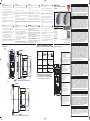
DIMENSIONS (MM) | MÅL (MM) | DIMENSIONES (MM) | ABMESSUNGEN (MM) | DIMENSIONS (MM) | DIMENSIONI (MM) |
РАЗМЕРЫ (ММ) | 尺寸 (MM)
IMPORTANT
Carlo Gavazzi is not to be held responsible for incorrect product
operation or damages resulting from improper use of the product
and/or use of the product outside its specified operating limits.
Products, specifications and data in this document are subject to
change without notice. The product is intended to be used by qual
-
ified personnel at their own discretion and risk. Should you require
information about installation, operation or maintenance of the prod
-
uct that is not covered in this document you should refer the matter
to an authorized Carlo Gavazzi representative. The information in this
document is not considered binding on any product warranty.
VIGTIGT
Carlo Gavazzi kan ikke holdes ansvarlig for ukorrekt anvendelse af
produktet eller skader opstået ved ukorrekt brug og/eller efter brug
af produktet til andet end de specificerede driftsbestemmelser.
Produkter, specifikationer og data i dette dokument kan ændres
uden varsel. Produktet er beregnet til anvendelse af uddannet per
-
sonale efter eget skøn og risiko. Hvis du har brug for oplysninger om
installation, drift eller vedligeholdelse af produktet, der ikke er dæk
-
ket af nærværende dokument, bør du rette henvendelse til en auto-
riseret repræsentant fra Carlo Gavazzi. Informationen i nærværende
dokument anses ikke for bindende for nogen produktgaranti.
IMPORTANTE
Carlo Gavazzi no se responsabiliza del uso incorrecto del producto o
de los daños ocasionados por un uso incorrecto del mismo y /o por
el uso del producto sin tener en cuenta los límites de funcionamiento
especificados. Los equipos, especificaciones y datos recogidos en
este documento están sujetos a cambios sin previo aviso. El equipo
debe usarse por personal cualificado y bajo su responsabilidad y
riesgo. En caso de necesitar más información sobre la instalación,
funcionamiento o mantenimiento del equipo que no se refleje en este
documento, póngase en contacto con un distribuidor autorizado de
Carlo Gavazzi. La información detallada en este documento no se
considera vinculante en ninguna garantía del producto.
WICHTIG
Carlo Gavazzi übernimmt keine Haftung für fehlerhafte Bedienung
des Produkts sowie für Schäden, die aus unsachgemäßer
Verwendung des Produkts und/oder dem Einsatz des Produkts
außerhalb der angegebenen Grenzbetriebsdaten resultieren. Die in
diesem Dokument beschriebenen Produkte, Spezifikationen und
technischen Daten können jederzeit ohne vorherige Ankündigung
geändert werden. Das Produkt ist nur für die Verwendung
durch qualifiziertes Fachpersonal nach eigenem Ermessen und
auf eigenes Risiko vorgesehen. Wenn Sie Informationen zur
Installation, zum Betrieb oder zur Wartung des Produkts benöti-
gen, die nicht in dieser Anleitung enthalten sind, wenden Sie sich
mit Ihrer Frage an einen autorisierten Vertriebspartner von Carlo
Gavazzi. Die Informationen in diesem Dokument sind nicht bind-
end hinsichtlich der Produktgewährleistung.
IMPORTANT
Carlo Gavazzi ne peut être tenu responsable d’une exploitation
incorrecte du produit ou d’avaries résultant d’une utilisation
incorrecte du produit et/ou hors des tolérances de fonctionne-
ment spécifiées. Les produits, caractéristiques et données
décrites dans le présent document peuvent changer sans préavis.
L’utilisation de ce produit est destinée à un personnel qualifié qui
l’exploite à sa guise et à ses propres risques. Pour plus amples
informations concernant l’installation, le fonctionnement ou la
maintenance du produit et ne figurant pas dans ce document,
consulter un concessionnaire agréé Carlo Gavazzi. Les informa-
tions contenues dans ce document ne constituent une obligation
de garantie de quelconque nature du produit.
IMPORTANTE
Carlo Gavazzi non può essere ritenuta responsabile per un
malfunzionamento o danni derivanti da un uso improprio del
prodotto e/o utilizzo del prodotto al di fuori dei suoi limiti operativi
specificati. Prodotti, specifiche e dati in questo documento sono
soggette a modifiche senza preavviso.Il prodotto è destinato ad
essere utilizzato da personale qualificato a propria discrezione e
rischio. Se avete bisogno di informazioni su installazione, funzi-
onamento o manutenzione del prodotto non riportate in questo
documento, dovete fare riferimento al personale autorizzato Carlo
Gavazzi. Le informazioni contenute in questo documento non
sono considerate vincolanti per alcuna garanzia sul prodotto.
PRODUCT | PRODUKT | PRODUCTO | PRODUKT | PRODUIT
| PRODOTTO | ИЗДЕЛИЕ | 产品
CARLO GAVAZZI LTD.
BLB042, Bulebel Industrial Estate, Zejtun
ZTN 3000, Malta
www.gavazziautomation.com
ВАЖНО
重要事项
Carlo Gavazzi не отвечает за некорректную работу или
повреждение УПП вследствие ненадлежащего применения
и/или эксплуатации УПП за пределами паспортных
характеристик. Изделия, характеристики и другие сведения в
настоящем документе могут быть изменены без уведомления.
УПП предназначено для эксплуатации квалифицированным
персоналом на его риск. За отсутствием какой-либо
информации по монтажу, эксплуатации или обслуживанию
изделий в настоящем документе следует обратиться к
официальному представителю Carlo Gavazzi. Информация
в настоящем документе не является основанием для
применения каких-либо гарантийных условий.
对于不当使用本产品和/或在规定的工作限值之外使用本产品而造成
的产品操作错误或损坏,Carlo Gavazzi 不承担任何责任。本文档
中的产品、规格和数据如有变更,恕不另行通知。本产品应由合格人
员自行斟酌使用并承担风险。如果您需要有关本文档未涵盖的产品安
装、操作或维护信息,应告知 Carlo Gavazzi 授权代表。本文档中
的信息不应视为对任何产品保修都有约束力。
RSWT..12
RSWT..16
TERMINATIONS | TERMINERINGER | TERMINALES |
ANSCHLÜSSE | TERMINATIONS | TERMINALI | КЛЕММЫ
| 端接
Use 75ºC copper Cu
conductors
Используйте
медные (Cu)
проводники на 75°C
使用 75°C 铜 (Cu)
导线
1/L1, 3/L2, 5/L3, 2/T1,
4/T2, 6/T3
Pozidrive Bit 2
2.5 Nm (22 lb.in.)
2.5...10 mm
2
AWG 6...14
2 x 2.5...4 mm
2
AWG 2
x 20
8.0 mm
A1, A2
Pozidrive Bit 0
0.6 Nm (5.3 lb.in.)
0.5...2.5 mm
2
AWG 18...10
6 mm
ST*, 11, 12, 21, 24
Pozidrive Bit 0
0.45 Nm (4.0 lb.in.)
0.05...2.5 mm
2
AWG 30...12
6 mm
A
Selector knobs: FLC, Ramp-up, Ramp-down
Omskifter: FLC, Ramp-op, Ramp-ned
Potenciómetros: FLC,Tiempo de rampa
ascendente, descendente
FLC: Anlauf-/Auslaufzeit
Sélecteurs: FLC, Temps d’accélération,décéléra-
tion
Selettori: FLC,Rampa accelerazione/decelerazione
Селекторы: Полный ток нагрузки (FLC), Профиль разгона
(Ramp-up), Профиль останова (Ramp-down)
选择器旋钮:FLC、斜升、斜降
B
LED: Alarm reset mode
LED: Alarm, reset mode
LED: LED modo Manual
LED: Manuell LED
LED: Mode de acquittement des alarmes
LED: Modalita’di reset allarmi
Светодиоды: Режим сброса тревоги
LED:报警复位模式
C
Test/Reset button
Test/rest trykknap
Botón Prueba/Puesta a cero (Test/Reset)
PRÜF-/RÜCKSETZTASTE
Touche Test/Acquittement
Pulsante Test/Reset
Кнопка Test/Reset
测试/复位按钮
D
LED: Supply, Status
LED: Forsyning, Status
LED: Alimentación, Estado
LED-Statusanzeigen: Versorgungsspannung,
Status
LED: Alimentation, État, Alarme
LED: Alimentazione, Stato, Allarme
Светодиоды: Питание (Supply), Состояние (Status)
LED:电源、状态
E
Auxiliary relays, ST (start signal) *
Hjjælpe relæ: ST (start signal) *
Relés auxiliares, ST (Señal de arranque) *
Hilfsrelais , ST-Signal (Startsignal) *
Relais auxiliaires, ST (signal de démarrage) *
Relè ausiliari, ST (tensione di controllo)*
Вспомогательные реле, ST (сигнал на
пуск) *
辅助继电器、ST(启动信号)*
RSWT..25
* RSWT..60 models only | Kun til modellerne RSWT..60 |
Solo para RSWT..60 | Nur bei den Modellen RSWT..60 |
Pour le versions RSWT..60 | Solo per il modello RSWT..60 |
Применимо только к RSWT..60 | 仅适用于RSWT..60

SHORT CIRCUIT PROTECTION | KORTSLUTNINGSBESKYTTE | PROTECCIÓN CONTRA CORTOCIRCUITOS
KURZSCHLUSSSCHUTZ | PROTECTION AU COURT-CIRCUIT | PROTEZIONE DA CORTO CIRCUITO | ЗАЩИТА
ОТ КОРОТКОГО ЗАМЫКАНИЯ | 短路保护
Note: For 24VDC control, A1 should be connected to the (+) terminal and A2 to the (-) terminal. | Примечание: Для напряжения управления 24 В DC A1 подключается на (+), а A2 – на (-). | 注:对于 24 VDC 控制,A1 应连接至 (+) 端子,A2 应连接至 (-) 端子。
CONNECTION DIAGRAM | TILSLUTNINGSDIAGRAMMER | DIAGRAMA DE CONEXIONES | ANSCHLUSSDIAGRAMME | DIAGRAMME DE RACCORDEMENT | DIAGRAMMA DELLE CONNESSIONI | СХЕМА ПОДКЛЮЧЕНИЯ |
连接图
RSWT40...E0V..
RSWT40...F0V..
RSWT40...E0V...
RSWT60...GGV..
SETTING PROCEDURE INDSTILLINGSPROCEDURE PROCÉDURE DE CONFIGURATION PROCEDURA DI AVVIAMENTO CONFIGURACIÓN
EINSTELLVORGANG
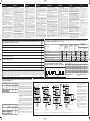
LED INDICATIONS, RELAY CONTACT POSITION | LED, POSITION FOR RELÆKONTAKT | INDICACIONES LED, POSICIÓN DEL CONTACTO DE RELÉ |
LED-ANZEIGEN , POSITION DER RELAISKONTAKTE | INDICATION LED, POSITION DES CONTACTS DE RELAIS | INDICAZIONI LED , POSIZIONE DEI
CONTATTI RELÈ | СВЕТОДИОД ИНДИКАЦИИ, | LED 指示、继电器接触位
State | Состояние | 状态
Green LED (Supply)
Зеленый светодиод
(питание)
绿色 LED(供电)
Yellow LED
(Ramp/Bypass)
Желтый светодиод
(Профиль/Байпас)
黄色 LED(斜坡/旁路)
Red LED (Alarm)
Красный светодиод
(Тревога)
红色 LED(报警)
Yellow LED (Manual)
Желтый светодиод
(Вручную)
黄色 LED(手动)
Relay Contact Position
Позиция контакта реле
继电器接触位
Alarm |
Тревога
|报警
(11, 12)
Bypass |
Байпас
|旁路
(21, 24)
Idle | Без нагрузки | 待机
/
Ramping | Профиль | 斜坡
/
Bypass | Байпас | 旁路
/
Alarm (Auto-recovery) | Тревога (автосброс) | 报警(自动恢复)
Alarm (Manual recovery) |
Тревога (ручная активация)
| 报警(手动恢复)
Internal fault | Внутренняя ошибка | 内部故障
/
TYPICAL SETTINGS | TYPISKE INDSTILLINGER | AJUSTES MÁS COMUNES | TYPISCHE EINSTELLUNGEN | PARAMÈTRES TYPIQUES |
IMPOSTAZIONI TIPICHE | ТИПИЧНЫЕ НАСТРОЙКИ | 典型设置
Ramp-up time (s)
Время профиля
(с)
斜升时间(秒)
Hydraulic pump | Hydraulikpumpe | Bomba hidráulica | Hydraulische Pumpe | Pompe hydraulique | Pompa idraulica | Гидравлический насос | 液压泵
1, 2
Scroll compressor | Scrollkompressor | Compresor Scroll | Scrollkompressoren | Compresseur à spirale | Compressore scroll | Спиральный компрессор | 涡旋式压缩机
1
Screw compressor | Skruekompressor | Compresor de tornillo | Schraubenverdichter | Compresseur à vis | Compressore a vite | Винтовой компрессор | 螺杆式压缩机
2, 5
Piston compressor | Stempelkompressor | Compresor de pistón | Hubkolbenverdichter | Compresseur à piston | Compressore a pistone | Поршневой компрессор | 活塞式压缩机
2
Low inertia fan | Ventilator med lav træghed | Ventilador de baja inercia | Lüfter mit niedrigem Trägheitsmoment | Ventilateur à faible inertie | Ventilatore a bassa
inerzia | Вентилятор малой инерции | 低惯量风扇
5, 10
High inertia fan | Ventilator med høj træghed | Ventilador de alta inercia | Lüfter mit hohem Trägheitsmoment | Ventilateur à haute inertie | Ventilatore ad alta inerzia
| Вентилятор большой инерции | 高惯量风扇
15, 20, 30
Centrifugal pump | Centrifugalpumpe | Bomba centrífuga | Zentrifugalpumpe | Pompe centrifuge | Pompa centrifuga | Центробежный насос | 离心泵
5, 10
Centrifugal blower | Centrifugal blæser | Ventilador centrífugo | Radialgebläse | Soufflante centrifuge | Ventilatore centrifugo | Центробежная воздуходувка | 离心鼓风机
5, 10
Mixer | Mixer | Mezcladora | Mischer | Mixeur | Miscelatore | Мешалка | 混合器
10, 15, 20
Note: Adjust the knob setting to the FLC value corresponding to the motor name plate to ensure proper overload protection. | Bemærk: Juster vælgerindstillingen til den FLC-værdi, der svarer
til mærkepladen på motoren, for at sikre korrekt beskyttelse mod overbelastning. | Nota: Colocar el potenciómetro en el valor de FLC correspondiente a la placa de características del motor
con el fin de asegurar que la protección contra sobrecargas es correcta. | Hinweis: Stellen Sie mit dem Drehpotentiometer Vollaststrom (FLC) den maximalen Betriebsstrom entsprechend dem
Motortypenschild ein, um einen ordnungsgemäßen Überlastschutz zu gewährleisten. | Nota: Régler le courant pleine charge en fonction des caractéristiques de la plaque de firme du moteur/de la
pompe afin d’assurer une protection correcte à la surcharge. | Nota: regolare il selettore FLC sul valore corrispondente al valore di targa riportato sulla targhetta del motore/pompa così da garantire
l’adeguata protezione da sovraccarico. | Примечание: Селектором установите значение тока полной нагрузки в соответствии с данными электродвигателя для обеспечения надлежащей защиты от
перегрузки. | 注:把旋钮设置调节至电机标牌所对应的 FLC 值,以确保适当的过载保护
The RSWT soft starter series feature 3-knob
settings and an additional push button to test the
overload protection, reset the alarms, setting the
alarm recovery to Manual or Auto and enable/
disable phase sequence protection.
Step 1: Set the ramp-up time: Set the knob to the
desired starting time as required for the specific
application.
Step 2: Set the ramp-down time: Set the knob
to the desired stopping time as required for the
specific application. In this case ramp-down time
can be set to a different value from that of the
ramp-up time. Note: If no soft-stop is required, set
the ramp-down knob to 0 sec.
Step 3: Set the full load current (FLC): Adjust the
knob setting to the FLC value corresponding to
the motor name plate to ensure proper overload
protection.
Step 4: Set the alarm recovery mode: Make
sure the RSWT is in idle mode (Green LED ON).
To set the alarm recovery to auto, press the Test/
Reset button for 5 secs. The MANUAL LED (yellow
LED) will turn OFF. To set the alarm recovery to
MANUAL the same procedure as described above
applies.
Step 5: Test the overload function. To make
sure that the overload function is working properly
press the TEST/RESET button for 1 sec. The
RSWT will trip and the red LED will flash 8 times
indicating an overload alarm. The alarm relay
(11,12) will also change state to Open.
RSWT-softstarter-serien har 3-vælgerindstillinger
og en ekstra trykknap til test af beskyttelse af
overbelastning, nulstilling af alarmer og til indstilling af
alarmgenoprettelse til manuel eller automatisk.
Trin 1: Indstil rampe-op-tidspunktet: Indstil
vælgeren til det starttidspunkt, der ønskes for den
pågældende brug.
Trin 2: Indstil rampe-ned-tidspunktet: Indstil
vælgeren til det stoptidspunkt, der ønskes for den
pågældende brug. I dette tilfælde kan rampe-ned-
tidspunktet indstilles til en anden værdi end værdien
for rampe-op-tidspunktet. Bemærk: Hvis der ikke
kræves soft-stop, indstilles rampe-ned-vælgeren fra
0 til 1 sek.
Trin 3: Indstil mærkeeffekt ved fuld belastning
(FLC): Juster vælgerindstillingen til den FLC-værdi,
der svarer til mærkepladen på motoren, for at sikre
korrekt beskyttelse mod overbelastning.
Trin 4: Indstil alarmgenoprettelsestilstand: Sørg
for, at RSWT’en er i idle-tilstand (grøn LED TIL).
Alarmgenoprettelse sættes til automatisk ved at
trykke på knappen Test/Reset (test/nulstil) i mindst
5 sekunder. MANUEL LED (gul LED) vil slå FRA,
hvilket indikerer, at alarmerne vil følge en automatisk
rutine for genoprettelse. Alarmgenoprettelse sættes
til MANUEL på samme måde som beskrevet herover
Bemærk: Standardindstillingen i RSWT er auto
alarmgenoprettelse (gul LED MANUEL OFF)
Trin 5: Test overbelastningsfunktionen Tryk på
knappen TEST/RESET (test/nulstil) i cirka 1 sek. for
at kontrollere, at overbelastningsfunktionen fungerer
korrekt. RSWT’en vil koble ud, og den røde LED vil
blinke 8 gange for at indikere en overbelastningsalarm.
Alarmrelæ (11,12) vil også ændre status til Åben.
Les démarreurs progressifs de la série RSWT comportent
3 boutons de réglage ; le bouton poussoir complémentaire
permet de tester la protection à la surcharge, d’acquitter
les alarmes et de régler l’acquittement manuel ou
automatique des alarmes.
Étape 1: Bouton de réglage du temps d’accélération.
Régler le temps de démarrage souhaité en fonction de
l’application particulière.
Étape 2: Bouton de réglage du temps de décélération.
Régler le temps d’arrêt souhaité en fonction de
l’application particulière. Dans ce cas, on peut régler le
temps de décélération à une valeur différente du temps
d’accélération. Nota : si l’arrêt progressif n’est pas requis,
régler le temps de décélération à 0 s avec le bouton de
réglage.
Étape 3: Bouton de réglage du courant pleine charge
(FLC). Régler le courant pleine charge en fonction des
caractéristiques de la plaque de firme du moteur afin
d’assurer une protection correcte à la surcharge.
Étape 4: Réglage du mode d’acquittement de l’alarme.
Constater que le RSWT est au repos (LED verte allumée).
Pour régler l’acquittement automatique de l’alarme,
appuyer sur le bouton Test/Acquittement pendant 5s.
En s’éteignant, la LED jaune (MANUEL) indique que
l’acquittement des alarmes est un processus automatique.
Pour régler l’acquittement des alarmes en mode manuel,
la procédure est identique à celle décrite plus haut. Nota:
Par défaut, l’acquittement des alarmes du RSWT est réglé
en manuel (LED jaune MANUAL OFF).
Étape 5: Test de la fonction de surcharge. Appuyer
sur la touche Test/Acquittement pendant 1 s environ et
constater le bon fonctionnement de la protection à la
surcharge. En cas de surcharge, le RSWT déclenche et
la LED rouge clignote huit (8) fois, signalant une condition
de surcharge. L’état du relais d’alarme (11,12) change
(ouverture).
ENGLISH DANSK ESPAÑOL DEUTSCH FRANCAIS ITALIANO
Die Motor-Softstarterserie RSWT besitzt drei
Drehknöpfe und einen zusätzlichen Drucktaster. Damit
kann der Überlastschutzes geprüft, die Alarmmeldungen
zurückgesetzt und die Alarmeinstellung auf manuellen
oder automatischen Alarm gesetzt werden. Weiterhin
kann damit der Phasenfolgefehler Alarm aktivieren /
deaktivieren werden.
Schritt 1: Einstellen der Anlaufzeit: Stellen Sie mit dem
Drehknopf die für die jeweilige Anwendung erforderliche
Startzeit ein.
Schritt 2: Einstellen der Auslaufzeit: Stellen Sie mit dem
Drehknopf die für die jeweilige Anwendung erforderliche
Stoppzeit ein. In diesem Fall kann die Auslaufzeit auf
einen von der Anlaufzeit abweichenden Wert eingestellt
werden. Hinweis: Wenn kein Sanftauslauf erforderlich
ist, stellen Sie den Knopf für die Auslaufzeit auf 0 s ein.
Schritt 3: Einstellen des Volllaststroms (FLC): Stellen
Sie mit dem Drehknopf den FLC-Wert entsprechend
dem Motortypenschild ein, um einen ordnungsgemäße
Überlastschutz zu gewährleisten.
Schritt 4: Einstellen des Alarmwiederherstellungsmodus:
Vergewissern Sie sich, dass sich das RSWT im Standby-
Modus befindet (grüne LED EIN). Drücken Sie, um die
Alarmeinstellung auf automatisch zu stellen, die Prüf-/
Rücksetztaste mindestens 5 s. Die LED für manuelle
Alarmrücksetzen (gelbe LED) erlischt. Dies zeigt an, dass
die Alarmeinstellung auf automatisch eingestellt ist. Um
die manuelle Alarmrücksetzen einzustellen, verfahren Sie
in der gleichen Weise wie oben angegeben.
Schritt 5: Prüfung der Überlastfunktion. Drücken Sie die
Prüf-/ Rücksetztaste etwa 1 s lang, um zu überprüfen,
ob die Überlastfunktion einwandfrei arbeitet. Das RSWT
löst aus und die rote LED blinkt 8 Mal zur Anzeige
eines Überlastalarms. Gleichzeitig öffnet des Alarmrelais
(11,12).
La serie RSWT de arrancadores suaves tiene 3
potenciómetros de ajuste y un pulsador adicional para
comprobar la protección contra sobrecargas, poner a cero
las alarmas y configurar la recuperación de alarmas en modo
Manual o Automático.
Paso 1: Ajuste del tiempo de rampa ascendente. Colocar
el potenciómetro en el tiempo de arranque deseado para la
aplicación en cuestión.
Paso 2: Ajuste del tiempo de rampa descendente. Colocar
el potenciómetro en el tiempo de parada deseado para la
aplicación en cuestión. En este caso el tiempo de rampa
descendente debe tener un valor diferente al de la rampa
ascendente.Nota: Si no es necesaria la parada suave, poner
el potenciómetro de rampa descendente a 0 seg.
Paso 3: Ajuste de la intensidad a plena carga (FLC). Colocar
el potenciómetro en el valor de FLC correspondiente a la
placa de características del motor con el fin de asegurar que
la protección contra sobrecargas es correcta.
Paso 4: Ajuste del modo de recuperación de alarmas.
Asegurar que RSWT está en estado de reposo (LED verde
encendido). Para establecer la recuperación de las alarmas
en AUTO, pulsar el botón de Prueba/Puesta a cero durante
un mínimo de 5 seg. El LED MANUAL (LED amarillo) se
apagará indicando que las alarmas seguirán una rutina
automática de recuperación. Para poner la recuperación de
las alarmas en MANUAL seguir el mismo procedimiento que
el arriba indicado.
Paso 5: Comprobación de la función de protección contra
sobrecargas: Para asegurar que la función de protección
contra sobrecargas funciona correctamente pulsar el botón
PRUEBA/PUESTA A CERO durante aproximadamente 1
segundo. RSWT se disparará y el LED rojo parpadeará 8
veces indicando una alarma de sobrecarga. El relé de alarma
(11,12) cambiará su estado a Abierto.
I soft starter della serie RSWT sono caratterizzati da 3
selettori di regolazione e da un pulsante per effettuare
il test della protezione da sovracorrente, resettare
gli allarmi, programmare il ripristino degli allarmi da
manuale ad automatico e per disattivare la protezione
di sequenza fasi.
Fase 1: set del tempo della rampa di avvio.
Posizionare il selettore scegliendo il tempo in funzione
della specifica applicazione.
Fase 2: set del tempo della rampa di decelerazione.
Posizionare il selettore scegliendo il tempo in funzione
della specifica applicazione. Nota: se non è richiesta
una rampa di decelerazione, posizionare il selettore
a 0 sec.
Fase 3: set della massima corrente di carico (FLC).
Posizionare il selettore in accordo con il valore di
corrente max. riportato sulla targhetta del motore così
da garantire la corretta protezione da sovracorrente.
Fase 4: set della modalità di ripristino allarme.
Assicurarsi che l’RSWT sia inattivo (led VERDE
ON). Per impostare il ripristino dell’allarme in modo
automatico, tenere premuto il pulsante Test/Reset
per 5 sec. L’indicatore luminoso MANUALE (led
GIALLO) si spegnerà. Per impostare nuovamente la
modalità di ripristino allarme su MANUALE, seguire
la procedura sopra descritta.
Fase 5: verifica della funzione di sovracorrente. Per
verificare il corretto funzionamento della funzione di
sovracorrente, premere il pulsante di TEST / RESET
per 1 sec. L’ RSWT effettuerà una simulazione e il led
ROSSO lampeggerà per 8 volte indicando l’allarme
di sovracorrente. I contatti del relè di uscita allarme
(11,12) cambieranno il loro stato e risulteranno
aperti.
ПРОЦЕДУРА НАСТРЙОКИ
РУССО
УПП RSWT имеют 3 рукоятки настройки и
дополнительную кнопку для контроля защиты
от перегрузки, сброса тревоги, задания режима
сброса Manual или Auto и подключения/ отключения
защиты от неправильного чередования фаз.
Шаг 1: задайте время профиля разгона:
Установите рукоятку в положение времени пуска,
соответствующего данному применению.
Шаг 2: задайте время профиля останова:
Установите рукоятку в положение времени
останова, соответствующего данному применению.
В этом случае профиль останова может быть
задан отличным от времени профиля разгона.
Примечание: Если плавный останов не нужен,
установите рукоятку времени профиля останова
в позицию 0 с.
Шаг 3: Задайте ток полной нагрузки (FLC):
Установите рукоятку на значение FLC,
соответствующее данным двигателя, для
надлежащей защиты от перегрузки.
Шаг 4: Задайте режим сброса тревоги:
Убедитесь, что RSWT без нагрузки (зеленый
светодиод ВКЛ.). Для задания автоматического
режима сброса нажмите и удерживайте кнопку
Test/Reset в течение 5 с. Светодиод MANUAL
(желтый) изменит состояние на ВЫКЛ. Для
задания ручного режима процедура аналогична
вышеописанной.
Шаг 6: Тестирование защиты от перегрузки
Нажмите и удерживайте кнопку TEST/RESET в
течение 1 с. RSWT отключится по защите, красный
светодиод даст 8 вспышек для индикации тревоги
по перегрузке. Тревожный контакт выходного реле
(11,12,14) перейдет в разомкнутое состояние.
设置步骤
简体中文
RSWT 软启动器系列的主要特征是三个旋钮
设定和一个额外按钮,以测试过载保护、
将报警复位、将报警恢复设定为“手动”
或“自动”以及启用/禁用相序保护。
第 1 步:设置斜升时间:将该旋钮设置到
具体应用所需的启动时间。
第 2 步:设置斜降时间:将该旋钮设置
到具体应用所需的停止时间。在这种情况
下,斜降时间的设定值可与斜升时间的设
定值不同。注:如果不需要软停止,则将
斜降旋钮设置为 0 秒。
第 3 步:设置满载电流 (FLC):把旋钮设
置调节至电机标牌所对应的 FLC 值,以确
保适当的过载保护
第 4 步:设置报警恢复模式:确保 RSWT
处于待机模式(绿色 LED 亮)。要将报
警恢复设定为“自动”,请按下“测试/复
位”按钮 5 秒。“手动 LED”(黄色
LED)将熄灭。将报警恢复设定为“手动”
的步骤同上。
第 5 步:禁用相序保护。确保 RSWT 处于
待机模式(绿色 LED 亮)。要禁用相序保
护,请按下“测试/复位”按钮 10 秒。相
序保护 LED(黄色 LED)将熄灭。如需重
新启用相序保护,请重复上述步骤。
第 6 步:测试过载功能。要确保过载功
能正常工作,请按“测试/复位”按钮 1
秒。RSWT 将脱扣,且红色 LED 将闪烁 8
次,指示过载报警。报警继电器(11、12
)的状态也会变为“开”。
FLASHING SEQUENCE | BLINKENDE SEKVENS | BLINKFREQUENZ
| SÉQUENCE DE CLIGNOTEMENT | SECUENCIA DE PARPADEO |
SEQUENZA LAMPEGGIANTE |
ПОСЛЕДОВАТЕЛЬНОСТЬ СВЕТОДИОДА
|
闪烁顺序
Type 1 (UL508) – Time Delay Fuses | Тип 1 (UL508) – Предохранители
затяжного срабатывания | 一类配合 (UL508) – 延时熔断器
Model
Модель
型号
Max. Fuse Size [A]
Макс. Номинал
предохранителя [A]
熔断器最大规格 [A]
Class
Класс
类
Current [kA]
Ток [кA]
电流 [kA]
Max. Voltage [VAC]
Макс. напряжение
[В AC]
最大电压 [VAC]
RSWT..12.V…. 20
RK5 5 400 / 600RSWT..16.V…. 20
RSWT..25.V…. 25
Type 1 (EN/IEC 60947-4-2) - Manual Motor Starters | Тип 1 (EN/IEC 60947-
4-2) – Ручные пускатели | 一类配合 (EN/IEC 60947-4-2) - 手动电机启动器
Model
Модель
型号
MMS Model No. *
MMS модель Np. *
MMS 型号*
Current [kA]
Ток [кA]
电流 [kA]
Max. Voltage [VAC]
Макс. напряжение
[В AC]
最大电压 [VAC]
RSWT..12.V…. GMS32H-17
5 / 3 400 / 600RSWT..16.V…. GMS32H-17
RSWT..25.V…. GMS32H-32
CURRENT / POWER RATINGS @ 40˚C |
НОМИНАЛЬНЫЙ ТОК/МОЩНОСТЬ ПРИ 40ºC
|
40ºC 下的电流/功率额定值
Part No. IEC Rated Current 220 - 240 VAC 380 - 415 VAC 440 - 480 VAC 550 - 600 VAC
RSWT4012…..
12 AAC 3 kW / 3HP 5.5 kW/ 5 HP - -
RSWT4016…..
16 AAC 4 kW / 5 HP 7.5 kW / 7.5 HP - -
RSWT4025…..
25 AAC 5.5 kW / 7.5 HP 11 kW / 10 HP - -
RSWT6012.....
12 AAC 3 kW / 3HP 5.5 kW/ 5 HP 5.5 kW / 7.5 HP 9 kW /10 HP
RSWT6016.....
16 AAC 4 kW / 5 HP 7.5 kW / 7.5 HP 9 kW / 10 HP 11 kW / 15 HP
RSWT6025.....
25 AAC 5.5 kW / 7.5 HP 11 kW / 10 HP 11 kW / 15 HP 20 kW / 20 HP
* Note: Products protected with manual motor starters must be wired with a minimum length of
2.0m (10.0m for 12,16A models) of Cu wire conductor with a maximum cross-sectional area of
2.5mm
2
for 12, 16A devices and 10mm
2
for higher currents. The length includes the conductors
from the voltage source to the manual motor starter to the soft starter and from the soft starter
to the load.
* Bemærk:
Produkter, der er beskyttet med manuelle motorstartere skal tilsluttes med en
længde på mindst 2,0 (10.0m for produkter 12, 16A) Cu wire. For produkter med 12, 16A skal
det maksimale tværsnitsareal være på 2.5mm
2
, for produkter med 25, 32, 45A skal maksimum
tværsnitsareal være af 10mm
2
.Længden inkluderer ledere fra spændingskilden til den manuelle
motorstarter, fra den manuelle motorstarter til softstarteren og fra softstarteren til belastningen.
*Nota: Los productos protegidos con arrancadores manuales deben utilizar un cable de cobre
de al menos 2.0m (10.0m para los equipos de 12, 16A) de longitud, con una sección mínima de
2.5mm
2
para los equipos de 12, 16 A y de 10mm
2
para corrientes más altas. La longitud incluye
conductores desde la toma de tensión de la protección al arrancador y del arrancador a la carga.
*Hinweis: Die Produkte, die über einen Motorschutzschalter geschützt werden, müssen mit einer
Mindestleitungslänge von 2,0 m (10.0m fur 12, 16A typen) angeschlossen werden und mit einer
max. Leitungsquerschnitten von 2.5 mm
2
für 12, 16 A Typen und 10 mm
2
für höhere Ströme.Die
Länge umfasst die Leitung von der Spannungsquelle zur Motorschutzschalter, Softstarter und
bis zum Softstarter zur Last.
* Nota: Les produits protégés par un démarrage manuel doivent être câblés avec un conducteur
Cu d’une longueur minimum de 2,0 (10,0m pour le produit 12, 16A). Pour le produit 12, 16A, la
section de câble maxi doit être de 2.5mm², pour les produits 25, 32, 45A, la section de câble
maxi doit être de 10mm². Les longueurs indiquées pour les conducteurs s’entendent de la source
de tension au démarreur manuel, du démarreur manuel au démarreur progressif et du démarreur
progressif à la charge.
* Nota: I prodotti protetti con salvamotori, devono essere cablati con cavo in rame della lunghezza
minima di 2,0m (10.0m per i dispositivi 12, 16A). Per i dispositivi con corrente nominale di 12, 16A
la sezione massima del cavo dovrà essere di 2.5mm
2
, per quelli con corrente nominale di 25, 32
e 45A la sezione massima dovrà essere di 10mm
2
.La lunghezza include i conduttori dalla linea di
alimentazione al salvamotore, dal salvamotore al soft start e dal soft start al motore.
* Примечание: электромонтаж УПП, защищенных ручными прерывателями, осуществляется
медным проводником длиной не менее 2,0м (10,0M для УПП током 12, 16A) с максимальным
сечением 2.5 мм2 для УПП током 12, 16A и 10 мм2 для УПП с более высоким током.
Длина включает проводник от источника тока от ручного прерывателя до УПП и от УПП
до нагрузки.
*注:用手动电机启动器保护的产品必须连接最小长度 2,0 m (10.0 m 的铜导线,12, 16A) 的
铜导线,12, 16A 设备对应的最大横截面积为 2.5 mm2,更高电流对应的最大横截面积为 10 mm2
。该长度包括从电压源至手动电机启动器、从手动电机启动器至软启动器、从软启动器至负载之间
的导线。
Overload Protection (UL 508)
This equipment provides motor overload protection at 120% of FLA.
(Full Load Amps)
Protection contre la surcharge (UL 508)
Ce produit intègre une protection contre la surcharge à 120% du
courant de pleine charge.
Note: Note: For RSWT60..GG models apply: 100 - 240VAC
across A1 - A2 terminals. For RSWT60..FF models apply:
24VAC/DC across A1 - A2 terminals.
Bemærk: Ved RSWT60..GG-modeller anvendes 100 - 240 VAC
til A1-, A2- klemmer. Ved RSWT60..FF-modeller anvendes 24
VAC/DC til A1-, A2-klemmer.
Nota: En los modelos RSWT60..GG se aplica 100-240 VCA a
través de los terminales A1, A2. En los modelos RSWT60..FF se
aplica 24 VCA/CC a través de los terminales A1, A2.
Hinweis: Bei den Modellen RSWT60..GG werden 100 – 240 VAC
an den Klemmen A1, A2 angelegt. Bei den Modellen RSWT60..
FF werden 24 VAC/DC an den Klemmen A1, A2 angelegt.
Nota: Types RSWT60..GG: appliquer une tension de 100 - 240
Vca aux bornes A1, A2. Types RSWT60..FF: appliquer une ten
-
sion de 24 Vca/cc aux bornes A1, A2.
Nota: per la versione RSWT60..GG applicare 100-240 VCA sui
terminali A1,A2. Per la versione RSWT60..FF applicare 240 VCC/
CA sui terminali A1,A2.
Примечание: Для моделей RSWT60..GG: 100 – 240 В AC на
клеммах A1 - A2. Для моделей RSWT60..FF: 24 B DC/AC на
клеммах A1 - A2.
注:对于 RSWT60..GG 型:A1 - A2 端子上应为 100 - 240VAC。
对于 RSWT60..FF 型:A1 - A2 端子上应为 24VAC/DC。
-
 1
1
-
 2
2


CARLO GAVAZZI RSWT4016F0V00 Benutzerhandbuch
- Typ
- Benutzerhandbuch
in anderen Sprachen
- English: CARLO GAVAZZI RSWT4016F0V00 User manual
- français: CARLO GAVAZZI RSWT4016F0V00 Manuel utilisateur
- español: CARLO GAVAZZI RSWT4016F0V00 Manual de usuario
- italiano: CARLO GAVAZZI RSWT4016F0V00 Manuale utente
- русский: CARLO GAVAZZI RSWT4016F0V00 Руководство пользователя
- dansk: CARLO GAVAZZI RSWT4016F0V00 Brugermanual
Verwandte Artikel
-
CARLO GAVAZZI RSWT6090GGV111 Installationsanleitung
-
CARLO GAVAZZI RSGD4070E0VX310C Installationsanleitung
-
CARLO GAVAZZI RSGT6045FFV111C Bedienungsanleitung
-
-
-
-
-
-
-
CARLO GAVAZZI RSBS2332A2V23C10HP Installationsanleitung