Bresser 7002550000000 Bedienungsanleitung
- Kategorie
- Wetterstationen
- Typ
- Bedienungsanleitung

Weather Station · Wetterstation ·
Comfort Weather Center 5in1
EN Instruction manual
DE Bedienungsanleitung

DE
Besuchen Sie unsere Website über den folgenden QR Code oder Weblink um weitere Informationen
zu diesem Produkt oder die verfügbaren Übersetzungen dieser Anleitung zu finden.
EN
Visit our website via the following QR Code or web link to find further information on this product or the
available translations of these instructions.
FR
Si vous souhaitez obtenir plus d’informations concernant ce produit ou rechercher ce mode d’emploi en
d’autres langues, rendez-vous sur notre site Internet en utilisant le code QR ou le lien correspondant.
NL
Bezoek onze internetpagina via de volgende QR-code of weblink, voor meer informatie over dit product
of de beschikbare vertalingen van deze gebruiksaanwijzing.
ES
¿Desearía recibir unas instrucciones de uso completas sobre este producto en un idioma determinado?
Entonces visite nuestra página web utilizando el siguiente enlace (código QR) para ver las versiones
disponibles.
IT
Desidera ricevere informazioni esaustive su questo prodotto in una lingua specifica? Venga a visitare il
nostro sito Web al seguente link (codice QR Code) per conoscere le versioni disponibili.
www.bresser.de/P7002550000000
www.bresser.de/warranty_terms
GARANTIE · WARRANTy · GARANTíA · GARANzIA


4
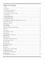
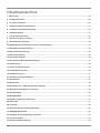
Table of contents
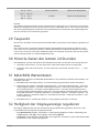
1 Imprint .............................................................................................................................................................6
2 Validity note ....................................................................................................................................................6
3 About this Instruction Manual.......................................................................................................................6
4 General safety instructions ...........................................................................................................................6
5 Parts overview and scope of delivery ..........................................................................................................8
6 Screen display ..............................................................................................................................................10
7 Before commissioning.................................................................................................................................11
8 Setting up power supply..............................................................................................................................11
9 Attaching rubber linings ..............................................................................................................................12
10 Assembling and installing the multifunctional remote sensor ................................................................12
11 Automatic time setting.................................................................................................................................13
12 Manual time setting ......................................................................................................................................13
13 Alarm setting.................................................................................................................................................13
14 Snooze function............................................................................................................................................13
15 Receiving measurements automatically ....................................................................................................14
16 Rainfall...........................................................................................................................................................14
17 HI/LO Alert.....................................................................................................................................................14
18 Clima indication (indoor) .............................................................................................................................15
19 Data clearing .................................................................................................................................................15
20 Pointing the sensor to the south ................................................................................................................15
21 Moon phases.................................................................................................................................................16
22 Weather Trend ..............................................................................................................................................17
23 Barometric / Atmospheric Pressure ...........................................................................................................17
24 Wind speed and direction............................................................................................................................18
25 Beaufort scale...............................................................................................................................................19
26 Wind chill factor............................................................................................................................................19
27 ‘Feels like’ temperature................................................................................................................................20
28 Heat index .....................................................................................................................................................20
29 Dew point ......................................................................................................................................................20
30 History record for the past 24 hours ..........................................................................................................21
31 MAX/MIN Weather data ................................................................................................................................21
32 Adjusting the display brightness................................................................................................................21
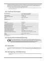
33 Technical data...............................................................................................................................................21
34 EC declaration of conformity ......................................................................................................................22

5
35 UKCA Declaration of Conformity ................................................................................................................22
36 Warranty ........................................................................................................................................................22
37 Cleaning and maintenance ..........................................................................................................................22
38 Disposal.........................................................................................................................................................23

6 / 48
1 Imprint
Bresser GmbH
Gutenbergstr. 2
46414 Rhede
Germany
www.bresser.de
For any warranty claims or service enquiries, please refer to the information on "Warranty" and "Ser-
vice" in this documentation. We apologize for any inconvenience caused by the fact that we cannot
process enquiries or submissions sent directly to the manufacturer's address.
Errors and technical changes excepted.
© 2021 Bresser GmbH
All rights reserved.
The reproduction of this documentation - even in extracts - in any form (e.g. photocopy, print, etc.) as
well as the use and distribution by means of electronic systems (e.g. image file, website, etc.) without
the prior written permission of the manufacturer is prohibited.
The designations and brand names of the respective companies used in this documentation are gen-
erally protected by trade, trademark and/or patent law in Germany, the European Union and/or other
countries.
2 Validity note
This documentation is valid for the products with the following article numbers:
7002550000000
Manual version: 0621
Manual designation:
Manual_7002550000000_Comfort-Weather-Center-5in1_en-de_BRESSER_v062021a
Always provide information when requesting service.
3 About this Instruction Manual
NOTICE
These operating instructions are to be considered a component of the device.
Read the safety instructions and the operating manual carefully before using this device.
Keep this instruction manual in a safe place for future reference. When the device is sold or given to
someone else, the instruction manual must be provided to the new owner/user of the product.
4 General safety instructions
DANGER
Risk of an electric shock!
This device contains electronic parts that are powered by a power source (AC adapter and/or batter-
ies). Improper use of this product may result in electric shock. Electric shock can cause serious or fatal
injuries. It is therefore imperative that you observe the following safety information.

7 / 48
• Never leave children unattended when handling the device! Follow the instructions carefully and
do not attempt to power this device with anything other than power sources recommended in this
instruction manual, otherwise there is a danger of an electric shock!
• Disconnect the power supply by pulling the mains plug when the appliance is not in use, in case of
a longer interruption of operation and before any maintenance and cleaning work.
• Place your device so that it can be disconnected from the power supply at any time. The power
outlet should always be near your appliance and should be easily accessible, as the plug of the
power cord serves as a disconnect device from the mains supply.
• To disconnect the unit from the mains, always pull the mains plug and never pull the cable!
• Check this device, cables and connections for damage before use.
• Never attempt to operate a damaged device, or a device with damaged electrical parts! Damaged
parts must be replaced immediately by an authorized service agent.
• Operate the device only in a completely dry environment and do not touch the device with wet or
damp body parts.
DANGER
Danger of suffocation!
Improper use of this product may result in suffocation, especially for children. It is therefore imperative
that you observe the following safety information.
• Keep packaging materials (plastic bags, rubber bands, etc.) away from children! There is a danger
of choking!
• This product contains small parts that can be swallowed by children! Choking hazard!
DANGER
Explosion hazard!
Improper use of this product may result in fire. It is essential that you observe the following safety in-
formation in order to avoid fires.
• Do not expose the device to high temperatures. Use only the supplied AC adapter or the recom-
mended batteries. Do not short-circuit the device or batteries or dispose of in fire! Excessive heat
and improper handling can cause short circuits, fires and even explosions!
NOTICE
Danger of material damage!
Improper handling may result in damage to the unit and/or accessories. Therefore, use the device only
in accordance with the following safety information.
• Do not disassemble the device! In the event of a defect, please contact your dealer. They will con-
tact the Service Center and can arrange the return of this device for repair if necessary.
• Do not expose the device to high temperatures and protect it from water and high humidity.
• Do not immerse the unit in water!
• Do not subject the device to excessive vibrations.
• Only use accessories and spare parts for this device that comply with the technical specifications.
• Use only the recommended batteries. Always replace weak or empty batteries with a new, com-
plete set of batteries at full capacity. Do not use batteries from different brands or types or with dif-
ferent capacities. Remove batteries from the device if it is not to be used for a longer period of
time!
• Do not use rechargeable AA batteries, as these will not give out the correct voltage for use.

8 / 48
NOTICE
Danger of voltage damage!
The manufacturer accepts no liability for voltage damage as a result of incorrectly inserted batteries,
or the use of an unsuitable mains adapter!
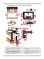
5 Parts overview and scope of delivery
A
B
1
2
5
6
3
7
4
8
12
13
20
19
18
22
18
23
24
25
26
9
10
21
11
14
17
16
15
27
28
29
32
30
31
C
E
33
36
37
35
39
40 42
43
45
46
41
36
34
34
37
35
44
40
38
38
D
F
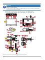
Illustration1: Parts overview for base station (top) and remote sensor (bottom)

9 / 48
1 BARO button (display change between hPa,
InHg or mmHg and selection of air pressure
type)
2 WIND button (display change between mean
value and current gust)
3 RAIN button (change between daily, weekly or
monthly rainfall)
4 ALARM/SNOOZE button (snooze function)
5 MAX/MIN button (display change between max-
imum, minimum or current value)
6 HISTORY button (show measured values of the
last 24 hours)
7 INDEX button (display change between dew
point, heat index and windchill index)
8 Display
9 Wall mount 10 Wall mount adapter
11 DOWN button (Value setting downwards) 12 UP button (Value setting upwards)
13 RESET button (reset all settings) 14 RCC button (initiate RCC signal reception)
15 SENSOR button (initiate data reception from
wireless sensor)
16 °C/°F switch (display change between °C or °F)
17 HI/LO/AUTO switch (display brightness) 18 Power output cable
19 TIME SET button 20 ALARM button
21 ALERT button 22 Battery compartment cover (base unit)
23 Battery compartment (base unit) 24 DC connection socket for barrel connector
25 DC power adapter with EU power plug 26 DC barrel connector
27 Funnel (measurement of the precipitation quant-
ity)
28 Antenna
29 Circular spirit level (horizontal alignment) 30 Windmill (wind speed measurement)
31 Wind vane (wind direction measurement) 32 Radiation shield
33 Mounting rod 34 Mounting foot
35 Aperture for vertical mounting 36 Tube clamp
37 Fixing screw 38 Fixing screw with nut
39 Aperture for horizontal mounting 40 Battery compartment cover (wireless sensor)
41 Fixing screw (battery compartment cover) 42 RESET button (reset all settings)
43 Aperture for the mounting rod in sensor head 44 Function light (wireless sensor)
45 Battery compartment (wireless sensor) 46 Sealing ring
Delivery content
Base unit (A), power adapter (B), wireless sensor (C), mounting rod with 2 screws and 2 nuts (D), tube
clamp with 4 screws and 4 nuts (E), mounting foot (F)
Required batteries (not included):
Station: 3 pcs. Micro batteries (1.5V, type AAA); sensor: 3 pcs. Mignon batteries (1.5V, type AA)
Also required (not included):
Small cross screwdriver, 4 wood screws

10 / 48
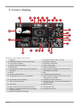
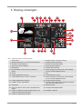
6 Screen display
9
3 8
29
28
15
16
21
2
6
1413
11
24
27
22
26
23
1
12
5
4
17
7
10
18
19
20
25
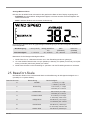
Illustration2: Screen display of the base unit
1 Weekday 2 Air pressure (hPa, inHg or mmHg)
3 AM/PM information in 12-hour time mode 4 Current time (hours)
5 Current time (minutes) 6 Current time (seconds)
7 Symbol for the RCC signal 8 Alarm symbol (bell)
9 Moon phase 10 Current wind direction
11 Climate indicator (indoors) (too cold, optimal,
too warm)
12 Alarm symbol for high (HI AL) or low (LO AL)
temperature or humidity
13 Month 14 Day
15 Humidity value (indoors) 16 Temperature value (indoors)
17 Temperature unit (°C or °F selectable) 18 Alarm symbol for high (HI AL) or low (LO AL)
temperature or humidity
19 Air humidity value (outdoors) 20 Temperature value (outdoors)
21 Signal strength indicator 22 Wind speed value: mean value (AVERAGE) or
last gust (GUST)
23 Heat Index 24 Beaufort scale
25 Alarm symbol for high wind speed (HI AL) 26 Wind speed scale
27 Graph for displaying rainfall and air pressure
history (24 hours)
28 Current air pressure
29 Graphical weather trend display

11 / 48
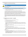
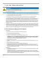
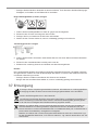
7 Before commissioning
NOTICE
Avoid connection faults!
In order to avoid connection problems between the devices, the following points must be observed
during commissioning.
1. Place the base unit (receiver) and sensor (transmitter) as close together as possible.
2. Connect the power supply to the base unit and wait until the indoor temperature is displayed.
3. Establish power supply for the sensor.
4. Set up/operate the base unit and sensor within the effective transmission range.
5. Make sure that the base unit and the radio sensor are set to the same channel.
When changing the batteries, always remove the batteries in both the base unit and the sensor and
reinsert them in the correct order so that the radio connection can be re-established. If one of the two
devices is operated via a mains power connection, the power connection for this device must also be
disconnected briefly when changing the battery. If, for example, only the batteries in the sensor are re-
placed, the signal cannot be received or can no longer be received correctly.
Note that the actual range depends on the building materials used in the building and the position of
the base unit and outdoor sensor. External influences (various radio transmitters and other sources of
interference) can greatly reduce the possible range. In such cases, we recommend finding other loca-
tions for both the base unit and the outdoor sensor. Sometimes a shift of just a few centimetres is
enough!
8 Setting up power supply
Base unit
1. Insert the DC plug into the connection socket on the base unit.
2. Insert the Euro plug into the mains power socket.
3. The device is powered on directly.
4. Wait until indoor temperature is displayed on the base unit.
NOTICE!For continuous operation, power supply via mains power is recommended. Altern-
atively, operation with batteries is also possible (permanent backlight not active). Proceed as
follows:
5. Remove the battery compartment cover.
6. Insert batteries into the battery compartment. Make sure that the battery terminals are correctly
aligned (+/-).
7. Replace the battery compartment cover.
8. Wait until indoor temperature is displayed on the base unit.
NOTICE!When changing the type of power supply (mains power or batteries), the power
supply is temporarily interrupted for technical reasons. All previously made settings will be
lost.
Wireless sensor
9. Remove the screw on the battery compartment cover with a suitable Phillips screwdriver and re-
move the battery compartment cover.
NOTICE!When removing the battery compartment cover, make sure that the narrow sealing
ring is not being lost by mistake. It is an important protection against water ingress and of-
ten sticks on the cover plate.

12 / 48
10. Insert batteries into the battery compartment. Make sure that the battery terminals are correctly
aligned (+/-).
11. Press RESET button. The function lamp lights up briefely.
12. Place the sealing ring on the edge of the battery compartment.
13. Replace and screw on the battery compartment cover.
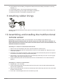
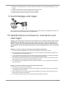
9 Attaching rubber linings
Attach the supplied self-adhesive rubber pads to the clamps as shown to ensure a firmer fitting of the
mounting rod.
10 Assembling and installing the multifunctional
remote sensor
Depending on the desired location, the remote sensor can be installed in two different ways.
NOTICE!During the assembly make sure that the upper part of the wind vanve is minimum 1.5
meters off the ground. Use the circular level in the sensor head to ensure a level installation. The
windmill must point to the North.
Assembly on a vertical or horizontal wooden element
1. Slide one end of the assembly bar into the aperture below the sensor head.
2. Slide one screw through the bore hole and put on the nut on the opposite site. Tighten the screw
connection by hand.
3. Depending on the desired orientation, slide the opposite end of the assembly bar into the aperture
for vertical or horizontal mounting of the assembly base.
4. Slide another screw through the bore hole of the assembly base and put on the nut on the oppos-
ite site. Tighten the screw connection by hand.
5. Place the assembly base with its bottom site first on a wooden element. Use 4 wood screws to
tighten it.
Assembly on a vertical or horizontal tube
6. Repeat steps 1 to 4 as before.
7. Place the assembly base with its bottom site first on the tube. Push the tube bracket against the
tube from the opposite site.
8. Slide 4 screws through the bore holes of the assemby base and through the bore holes of the tube
bracket on the other site.
9. Put on the 4 nuts and tighten the screw connection by hand.

13 / 48
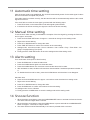
11 Automatic time setting
After the power supply was established, the clock will automatically search for the radio signal. It takes
about 3-8 minutes to complete this process.
If the radio signal is received correctly, the date and time will be set automatically and the radio control
signal icon turns on.
If the clock fails to receive the time signal, go ahead with the following steps:
1. Press RCC button on the base station until radio signal symbol flashes.
2. If the device is still not receiving the signal, the time must be set manually.
12 Manual time setting
To set the time / date manually, first disable the reception of the time signal by pressing the RCC but-
ton for approx. 8 seconds.
1. Press and hold TIME SET button for approx. 3 seconds to change to time setting mode.
2. Digits to be set are flashing.
3. Press UP or DOWN button to change the value.
4. Press TIME SET button to confirm and continue to the next setting.
5. Settings order: 12/24-hours mode > Hours > Minutes > Year > Month > Day > Time offset > Lan-
guage > Daylight Saving Time (DST)
6. Finally press the TIME SET button to save the settings and exit the setting mode.
13 Alarm setting
Turn on/off Alarm clock (and Ice Alert function)
1. Press ALARM button to show the alarm time.
2. Press the ALARM button again to activate the alarm.
3. Press the ALARM button one more time to activate the alarm with ice alert.
4. With activated ice alert, the alarm will sound 30 minutes earlier if outside temperature is below -3°
C.
5. To disable the alarm and ice alert, press the ALARM button until the alarm icons disappear.
Set Alarm time
6. Press and hold ALARM button for approx. 3 seconds to enter the alarm time setting mode.
7. Digits to be set are flashing.
8. Press UP or DOWN button to change the value.
9. Press ALARM button to confirm and continue to the next setting.
10. Settings order: Hours > Minutes
11. Finally press the ALARM button to save the settings and exit the setting mode.
14 Snooze function
1. When the alarm sound starts, press the ALARM/SNOOZE button to activate the Snooze function.
The Alarm will sound again after 5 minutes.
2. When the alarm sound starts, press the ALARM button or press and hold the ALARM/SNOOZE
button for approx. 3 seconds, to stop the alarm.
3. The alarm will be turned off automatically if no button is pressed within 2 minutes.

14 / 48
15 Receiving measurements automatically
Once the power supply is enabled, the base station will display the measurement readings. Readings
from the remote sensor will be displayed within 3 minutes after powering it on.
Read the detailed manual for more information about readings (see download information on page 2).
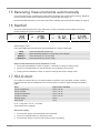
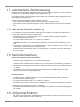
16 Rainfall
The base station displays how many millimeters / inches of rainfall are accumulated over a time
period, based on the current rainfall rate.
Rainfall rate Daily rainfall Weekly rainfall Monthly rainfall
Select display mode
Press the RAIN button several times until the desired time range is displayed:
RATE Current rainfall rate in past hour
DAILY Total rainfall rate within the current day, from midnight
WEEKLY Total rainfall rate for current week
MONTHLY Total rainfall rate for current month
Select rainfall measurement unit (millimeter or inch)
1. Press and hold RAINFALL button for approx. 3 seconds to change to setting mode.
2. Press UP or DOWN button to change between mm (millimeter) and in (inch).
3. Finally press the RAINFALL button to save the settings and exit the setting mode.
17 HI/LO Alert
HI/LO alert are used to alert you of certain weather conditions. Once activated, an alarm sound is
triggered and the alert icon flashes as soon as a set value is reached. Supported areas and alarm
types:
Area Type of alert available
Indoor temperature HI AL / LO AL
Indoor humidity HI AL / LO AL
Outdoor temperature HI AL / LO AL
Outdoor humidity HI AL / LO AL
Rainfall (daily) HI AL*
Wind speed HI AL
HI AL = High alert / LO AL = Low alert
*Daily rainfall since midnight
HI/LO alert setting
1. Press ALERT button until the desired area is selected.
2. Press UP or DOWN button to change the value.
3. Press ALERT button to confirm and continue to the next setting.

15 / 48
Enable/Disable HI/LO Alert
4. Press ALERT button until the desired area is selected.
5. Press ALARM button, to activate the alarm.
6. Press ALERT button to confirm and continue to the next setting.
Note:
7. The unit will automatically exit setting mode in 5 seconds if no button is pressed.
8. When ALERT alarm is on, the area and type of alarm that triggered the alarm will be flashing and
the alarm will sound for 2 minutes.
9. Press SNOOZE/LIGHT button when alarm sounds to interrupt the alarm. The alarm will then start
again after 2 minutes.
Data clearing
10. Press and hold HISTORY button for approx. 3 seconds.
11. Press UP or DOWN button to choose YES or NO.
12. Press HISTORY button to confirm. This will clear out any rainfall data recorded before.
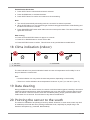
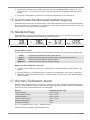
18 Clima indication (indoor)
1
2
3
1 too cold 2 comfortable
3 too warm
The clima indication is a pictorial indication based on indoor air temperature and humidity in an at-
tempt to determine comfort level.
Note:
• Comfort indication can vary under the same temperature, depending on the humidity.
• There is no comfort indication when temperature is below 0° C (32° F) or over 60° C (140° F)
19 Data clearing
During installation of the outdoor sensor, the sensor could have been triggered, resulting in erroneous
rainfall and wind measurements. After the installation user may clear all the erroneous data from the
main unit without a need to reset the clock and re-establish pairing. Simply press and hold the HIS-
TORY button for 10 seconds. This will clear out any data recorded before.
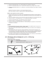
20 Pointing the sensor to the south
The sensor is calibrated to be pointing to North by default. However, in some cases, users may wish
to install the product with the arrow pointing towards the South, especially for people living in the
Southern hemisphere (e.g. Australia, New Zealand).

16 / 48
1
2
1 Northern hemisphere 2 Southern hemisphere
1. First install the outdoor sensor with its arrow pointing to the south. Please refer to "Installation"
chapter for mounting details.
2. Press and hold the WIND button for approx. 8 seconds until the upper part (northern hemisphere)
of the compass rose is blinking.
3. Press the UP or DOWN button to change to lower part (southern hemisphere).
4. Press the WIND button to confirm and exit.
Note:
Changing the hempisphere setting will automatically switch the direction of the moon phase on the dis-
play.
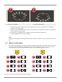
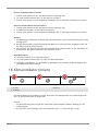
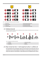
21 Moon phases
In the Northern hemisphere, the moon waxes from the right. Hence the sun-lit area of the moon moves
from right to left in the Northern hemisphere, while in the Southern hemisphere, it moves from left to
right. Below are the 2 tables which illustrate how the moon will appear on the main unit.
A
1
2
3
4
5
6
7
8
B
1
2
3
4
5
6
7
8
Illustration3: (A) Northern hemisphere, (B) Southern hemisphere

17 / 48
1 New moon 2 Waxing crescent
3 First quarter 4 Waxing gibbous
5 Full moon 6 Waning gibbous
7 Third quarter 8 Waning crescent
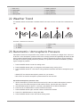
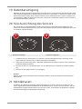
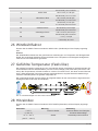
22 Weather Trend
The weather station will calculate a weather trend for the next 12 hours on basis of the measured val-
ues.
1
2
3
4
5
6
Illustration4: Weather trend indicators
1 Sunny 2 Partly cloudy
3 Cloudy 4 Rain
5 Storm 6 Snow
23 Barometric / Atmospheric Pressure
Atmospheric Pressure is the pressure at any location on earth, caused by the weight of the column of
air above it. One atmospheric pressure refers to the average pressure and gradually decreases as alti-
tude increases. Meteorologists use barometers to measure atmospheric pressure. Since variation in
atmospheric pressure is greatly affected by weather, it is possible to forecast the weather by measur-
ing the changes in pressure.
1. Press the BARO button to enter the setting mode.
2. Press the BARO button again, to change the unit between inHg / mmHg / hPa.
3. Press the BARO button for 3 seconds to change between absolute and relative atmospheric pres-
sure.
• ABSOLUTE: the absolute atmospheric pressure of your location.
• RELATIVE: the relative atmospheric pressure based on the sea level.
Set relative atmospheric pressure value
4. Get the atmospheric pressure data of the sea level (it is also the relative atmospheric pressure
data of your home area) through the local weather service, internet and other channels.
5. Hold the BARO button for approx. 3 seconds, until ABSOLUTE or RELATIVE flashes.
6. Press the UP or DOWN button to switch to RELATIVE mode.
7. Press the BARO button again, and the number for RELATIVE flashes.
8. Press UP or DOWN button to change the value.
9. Press the BARO button to save and exit the setting mode.

18 / 48
NOTE
10. The default relative atmospheric pressure value is 1013 mb/hPa (29.91 inHg), which refers to the
average atmospheric pressure.
11. When you change the relative atmospheric pressure value, the weather indicators will change
along with it.
12. The built-in barometer can notice the environmental absolute atmospheric pressure changes.
Based on the data collected, it can predict the weather conditions in the forthcoming 12 hours.
Therefore, the weather indicators will change according to the detected absolute atmospheric
pressure after you operate the clock for 1 hour.
13. The relative atmospheric pressure is based on the sea level, but it will change with the absolute at-
mospheric pressure changes after operating the clock for 1 hour.
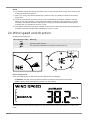
24 Wind speed and direction
Reading the wind direction
Wind direction indic-
ator
Meaning
Real-time wind direction
Wind directions appeared in the last 5 minutes (max. 6)
Select display mode
Press the WIND button several times until the desired rate is displayed:
• AVERAGE: average of all wind speed numbers recorded in the previous 30 seconds
• GUST: highest wind speed (gust) recorded from last reading
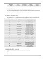
The wind level provides a quick reference on the wind condition and is indicated by a series of text
icons:

19 / 48
Wind level LIGHT MODERATE STRONG STORM
Speed 1 – 19 km/h 20 – 49 km/h 50 – 88 km/h > 88 km/h
Select wind speed unit
1. Press the WIND button for approx. 3 seconds to enter the setting mode.
2. Press the UP or DOWN button to change the unit between mph (miles per hour), m/s (miles per
second), km/h (kilometer per hour) or knots.
3. Press the WIND button to save the settings and exit the setting mode.
25 Beaufort scale
The Beaufort scale is an international scale of wind velocities from 0 (calm) to 12 (Hurricane force).
Beaufort number Description Speed
0 calm < 1 km/h | < 1 mph
< 1 knots | < 0.3 m/s
1 light air 1.1-5.5 km/h | 1-3 mph
1-3 knots | 0.3-1.5 m/s
2 light breeze 5.6-11 km/h | 4-7 mph
1-3 knots | 0.3-1.5 m/s
3 gentle breeze 12-19 km/h | 8-12 mph
7-10 knots | 3.5-5.4 m/s
4 moderate breeze 20-28 km/h | 13-17 mph
11-16 knots | 5.5-7.9 m/s
5 fresh breeze 29-38 km/h | 18-24 mph
17-21 knots | 8.0-10.7 m/s
6 strong gale 39-49 km/h | 25-30 mph
22-27 knots | 10.8-13.8 m/s
7 high wind 50-61 km/h | 31-38 mph
28-33 knots | 13.9-17.1 m/s
8 gale 62-74 km/h | 39-46 mph
34-40 knots | 17.2-20.7 m/s
9 strong gale 75-88 km/h | 47-54 mph
41-47 knots | 20.8-24.4 m/s
10 storm 89-102 km/h | 55-63 mph
48-55 knots | 24.5-28.4 m/s
11 violent storm 103-117 km/h | 64-73 mph
56-63 knots | 28.5-32.6 m/s
12 hurricane force > 118 | > 74 mph
> 64 knots | 32.7 m/s
26 Wind chill factor
Press the INDEX button several times until WIND CHILL is displayed.
Note:

20 / 48
The wind chill factor is based on the common effects of temperature and wind speed.The displayed
wind chill is calculated solely from temperature and wind speed and is measured by the outdoor
sensor.
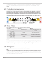
27 ‘Feels like’ temperature
The 'feels like' temperature corresponds on the outside temperature perceived by the human body. It
is a collective mix of wind chill factor (18°C/64°F or lower) and heat index (26°C/78°F or higher). At
temperatures in the range between 18°C/64°F and 26°C/78°F, where both wind and humidity have
less influence on the temperature, the unit displays the actual measured outdoor temperature as the
‘feels like’ temperature.
The following graph illustrates the increasing danger to the human organism when the heat index or
wind chill increases.
Illustration5: Proportionality of heat index and wind chill.
28 Heat index
Press the INDEX button several times until HEAT INDEX is displayed.
Heat index Warning Meaning
> 55° C
(> 130° F)
Extreme danger Strong risk of dehydration / sun
stroke
41° C – 54° C
(106° F – 129° F)
Danger Heat exhaustion likely
33° C – 40° C
(91° F – 105° F)
Extreme caution Possibility of dehydration
27° C – 32° C
(80° F – 90° F)
Caution Possibility of heat exhaustion
Notice:
The perceived temperature is based on the common effects of temperature and humidity. Heat index
is only calculated when room temperature is at 27° (80° F) or higher. The displayed perceived temper-
ature is calculated solely from temperature and humidity and is measured by the outdoor sensor.
29 Dew point
Press the INDEX button several times until DEW POINT is displayed.
Note:
The dew point is the temperature below which the water vapor in air at constant barometric pressure
condenses into liquid water at the same rate at which it evaporates. The condensed water is called
dew when it forms on a solid surface. The dewpoint temperature is calculated from the indoor temper-
ature and humidity measured at the main unit.
Seite wird geladen ...
Seite wird geladen ...
Seite wird geladen ...
Seite wird geladen ...
Seite wird geladen ...
Seite wird geladen ...
Seite wird geladen ...
Seite wird geladen ...
Seite wird geladen ...
Seite wird geladen ...
Seite wird geladen ...
Seite wird geladen ...
Seite wird geladen ...
Seite wird geladen ...
Seite wird geladen ...
Seite wird geladen ...
Seite wird geladen ...
Seite wird geladen ...
Seite wird geladen ...
Seite wird geladen ...
Seite wird geladen ...
Seite wird geladen ...
Seite wird geladen ...
Seite wird geladen ...
Seite wird geladen ...
Seite wird geladen ...
Seite wird geladen ...
Seite wird geladen ...
-
 1
1
-
 2
2
-
 3
3
-
 4
4
-
 5
5
-
 6
6
-
 7
7
-
 8
8
-
 9
9
-
 10
10
-
 11
11
-
 12
12
-
 13
13
-
 14
14
-
 15
15
-
 16
16
-
 17
17
-
 18
18
-
 19
19
-
 20
20
-
 21
21
-
 22
22
-
 23
23
-
 24
24
-
 25
25
-
 26
26
-
 27
27
-
 28
28
-
 29
29
-
 30
30
-
 31
31
-
 32
32
-
 33
33
-
 34
34
-
 35
35
-
 36
36
-
 37
37
-
 38
38
-
 39
39
-
 40
40
-
 41
41
-
 42
42
-
 43
43
-
 44
44
-
 45
45
-
 46
46
-
 47
47
-
 48
48


Bresser 7002550000000 Bedienungsanleitung
- Kategorie
- Wetterstationen
- Typ
- Bedienungsanleitung
in anderen Sprachen
- English: Bresser 7002550000000 Owner's manual
Verwandte Artikel
-
Bresser 7002550000000 Bedienungsanleitung
-
Bresser 9080500 - Colour Weather Center 5-in-1 National Geographic Bedienungsanleitung
-
-
-
-
-
-
Bresser Profi 7002540CM3000 Bedienungsanleitung
-
Bresser 7002525 Bedienungsanleitung
-
Bresser 7002510 Bedienungsanleitung
Andere Dokumente
-
National Geographic 256-color and RC weather center 5-in-1 Bedienungsanleitung
-
Emos ESW5003 Benutzerhandbuch
-
-
Emos ESW5002 Benutzerhandbuch
-
National Geographic 9070110 Bedienungsanleitung
-
Renkforce E0202LNS Bedienungsanleitung
-
-
-
-
Extech Instruments WTH600-E-KIT Benutzerhandbuch