Bresser 7002525 Bedienungsanleitung
- Kategorie
- Wetterstationen
- Typ
- Bedienungsanleitung
Dieses Handbuch ist auch geeignet für

Weather Station · Wetterstation ·
Colour Weather Center 5in1
EN Instruction manual
DE Bedienungsanleitung

DE
Besuchen Sie unsere Website über den folgenden QR Code oder Weblink um weitere
Informationen zu diesem Produkt oder die verfügbaren Übersetzungen dieser Anleitung
zu nden.
EN
Visit our website via the following QR Code or web link to nd further information on this
product or the available translations of these instructions.
FR
Si vous souhaitez obtenir plus d’informations concernant ce produit ou rechercher ce
mode d’emploi en d’autres langues, rendez-vous sur notre site Internet en utilisant le
code QR ou le lien correspondant.
NL
Bezoek onze internetpagina via de volgende QR-code of weblink, voor meer informatie
over dit product of de beschikbare vertalingen van deze gebruiksaanwijzing.
ES
¿Desearía recibir unas instrucciones de uso completas sobre este producto en un idioma
determinado? Entonces visite nuestra página web utilizando el siguiente enlace (código
QR) para ver las versiones disponibles.
IT
Desidera ricevere informazioni esaustive su questo prodotto in una lingua specica?
Venga a visitare il nostro sito Web al seguente link (codice QR Code) per conoscere le
versioni disponibili.
www.bresser.de/P7002525
www.bresser.de/P7902525
www.bresser.de/P7802525
www.bresser.de/warranty_terms
GARANTIE · WARRANTY · GARANTÍA · GARANZIA
RECYCLAGE (TRIMAN/FRANCE)


4
Table of contents
1 Imprint ............................................................................................................................................................. 6
2 Validity note .................................................................................................................................................... 6
3 Features .......................................................................................................................................................... 6
4 About this Instruction Manual....................................................................................................................... 7
5 Parts overview base station .......................................................................................................................... 7
6 Scope of delivery............................................................................................................................................ 8
7 Screen display ................................................................................................................................................ 8
8 Establish power supply ................................................................................................................................. 9
9 Attaching rubber linings................................................................................................................................ 9
10 Assembling and installing the multifunctional remote sensor................................................................ 10
11 Signal transmission ..................................................................................................................................... 11
12 Automatic time setting................................................................................................................................. 11
13 Manual time setting...................................................................................................................................... 11
14 Time zone setting ......................................................................................................................................... 11
15 Setting Daylight Saving Time (DST) ........................................................................................................... 12
16 Alarm setting ................................................................................................................................................ 12
17 Snooze function ........................................................................................................................................... 12
18 Receiving measurements automatically .................................................................................................... 12
19 Rainfall .......................................................................................................................................................... 13
20 HI/LO Alert..................................................................................................................................................... 13
21 Clima indication (indoor) ............................................................................................................................. 14
22 Data clearing................................................................................................................................................. 14
23 Pointing the sensor to the south ................................................................................................................ 14
24 Moon phases ................................................................................................................................................ 15
25 Weather trend ............................................................................................................................................... 16
26 Barometric / Atmospheric Pressure ........................................................................................................... 16
27 Wind speed and direction............................................................................................................................ 17
28 Beaufort scale............................................................................................................................................... 19
29 Wind chill factor ........................................................................................................................................... 19
30 Temperature display .................................................................................................................................... 20
31 Feels like temperature ................................................................................................................................. 20
32 Heat index ..................................................................................................................................................... 20
33 Dew point ...................................................................................................................................................... 20
34 History record for the past 24 hours .......................................................................................................... 21

5
35 MAX/MIN Weather data ................................................................................................................................ 21
36 Display brightness regulation..................................................................................................................... 21
37 Disposal ........................................................................................................................................................ 21
38 Technical data .............................................................................................................................................. 21
39 Warranty........................................................................................................................................................ 22
40 CE declaration of conformity ...................................................................................................................... 22

6 / 44
1 Imprint
Bresser GmbH
Gutenbergstr. 2
46414 Rhede
Germany
www.bresser.de
For any warranty claims or service inquiries, please refer to the information on "Warranty" and "Ser-
vice" in this documentation. We ask for your understanding that unsolicited returns cannot be pro-
cessed.
Errors and technical changes excepted.
© 2023 Bresser GmbH
All rights reserved.
The reproduction of this documentation - even in extracts - in any form (e.g. photocopy, print, etc.) as
well as the use and distribution by means of electronic systems (e.g. image file, website, etc.) without
the prior written permission of the manufacturer is prohibited.
The designations and brand names of the respective companies used in this documentation are gen-
erally protected by trade, trademark and/or patent law in Germany, the European Union and/or other
countries.
2 Validity note
This documentation is valid for the products with the following article numbers:
7002525 7902525 7802525
Manual version: 0124
Manual designation:
Manual_7002525-7902525-7802580_Colour-Weather-Center-5in1_en-de_BRESSER_v012024a
Always provide information when requesting service.
3 Features
• Precipitation measurement
• Measurement of wind speed
• Wind direction measurement
• DCF radio clock reception and display
• Alarm with snooze function
• Outdoor temperature alarm (frost warning)
• Outdoor temperature (in °C or °F)
• Indoor temperature (in °C or °F)
• Humidity indoor/outdoor
• Air pressure
• Weather index: "Feels like", Wind chill, Heat index, Dew point
• Beaufort scale
• Lowest and highest value display
• Max/min values storage
• Weather Forecast (12~24 hours)
• Moon phases
• Colour display

7 / 44
• Backlight
4 About this Instruction Manual
NOTICE
These operating instructions are to be considered a component of the device.
Read the safety instructions and the instruction manual carefully before using this device.
Keep these instruction manual in a safe place for future reference. If the device is sold or passed on,
the instruction manual must be passed on to any subsequent owner/user of the product.
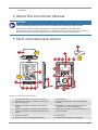
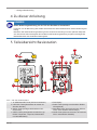
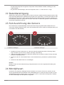
5 Parts overview base station
1
2
18
17
22
21
2013
9
10
11 1912
15
A
C
3
5
487
6
9
16
14
23
B
Illustration1: All parts of the base station
1 ALARM/SNOOZE button (snooze function) 2 Colour display
3 HISTORY key (retrieve measured values from
the last 24 hours)
4 RAIN button (displays various precipitation
values)
5 BARO key (display of different air pressure
values)
6 MAX/MIN key (change between maximum,
minimum or current value display)
7 INDEX key (display change between felt tem-
perature, dew point, heat index and wind chill
factor)
8 WIND key (change between average and cur-
rent wind gust)
9 Stand, removable 10 Wall bracket
11 ALERT key (e.g. set temperature alarm) 12 ALARM button (wake-up call setting)

8 / 44
13 CLOCK SET key (manual time setting) 14 HI/LO/AUTO switch (display brightness)
15 °C/°F key (display changes between °C and
°F)
16 RCC Button (Initiate time signal reception)
17 Battery compartment (cover) 18 USB power socket for mains adapter
19 DOWN key (value change downwards) 20 UP key (value change upwards)
21 RESET button (reset all settings) 22 SENSOR button (sensor search)
23 AC adapter with DC plug (USB)
6 Scope of delivery
Base station (A), power adapter (B), stand (C), multifunctional outdoor sensor (D), mounting rod (E),
mounting shoe (F), pipe clamp (G), screws, instruction manual
Also required (not included in delivery):
3 x 1.5V batteries type AA/LR6 (outdoor sensor)
Backup battery (not included in delivery):
1 piece of 3V battery type CR2032 (base station)
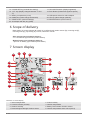
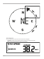
7 Screen display
2
24
8
3
7
27
1
4
6
25 30
28 32 31
29
26
9
12
13
16
10
11
14
15
17
18
19 23
24
5
20
21
22
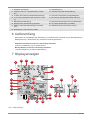
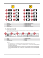
Illustration2: Screen display
1 Internal temperature 2 Indoor humidity
3 Comfort indicator (climate) 4 Outdoor temperature
5 Outdoor humidity 6 Battery level indicator Outdoor sensor
7 Received signal strength Outdoor sensor 8 Outdoor temperature alarm active (HI/LO)

9 / 44
9 Wind direction 10 Wind direction indicator
11 Wind direction indicator (of the last 5
minutes)
12 Wind speeds
13 Wind alarm active (HI) 14 Wind speed value: mean value (AVERAGE) or
last gust (GUST)
15 Wind speed value (mph, m/s, km/h, knot) 16 Beaufort scale for wind force classification
17 INDEX Display change between: feels like,
wind chill factor, heat index and dew point
18 Current time
19 Symbol for active daylight saving time
(DST)
20 Symbol for the radio signal
21 Wake-up call active 22 Moon phase
23 Day of the week 24 Weather forecast
25 Display change: Relative or absolute air
pressure
26 Air pressure (hPa, inHg or mmHg)
27 Air pressure history (24 hours) 28 History of air pressure values
29 Precipitation alarm active (HI/LO) 30 Precipitation quantity
31 Precipitation history (5 days) 32 Timing information
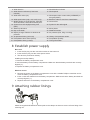
8 Establish power supply
Base unit
1. Insert the DC plug into the connection socket on the base unit.
2. Insert the Euro plug into the mains power socket.
3. The device is powered on directly.
Installing the backup battery:
1. Remove the battery compartment cover.
2. Insert the battery into the battery compartment. Make sure that the battery terminals are correctly
aligned (+/-).
3. Replace the battery compartment cover.
Wireless sensor
4. Remove the screw on the battery compartment cover with a suitable Phillips screwdriver and re-
move the battery compartment cover.
5. Insert 2 x AA size batteries into the battery compartment. Make sure that the battery terminals are
correctly aligned (+/-).
6. Replace and screw on the battery compartment cover.
9 Attaching rubber linings
Attach the supplied self-adhesive rubber pads to the clamps as shown to ensure a firmer fitting of the
mounting rod.

10 / 44
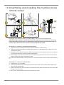
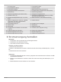
10 Assembling and installing the multifunctional
remote sensor
12
34
5
Depending on the desired location, the wireless sensor can be mounted in different ways.
NOTICE!During installation, always ensure that the upper part of the wind vane is at least 1.5
metres above the ground. Ensure an absolutely horizontal position when mounting using the
circular level in the sensor head. The wind vane must always face north.
Assembly on a vertical or horizontal wooden element
1. Slide one end of the assembly bar into the aperture below the sensor head.
2. Slide one screw through the bore hole and put on the nut on the opposite site. Tighten the screw
connection by hand.
3. Depending on the desired orientation, slide the opposite end of the assembly bar into the aperture
for vertical or horizontal mounting of the assembly base.
4. Slide another screw through the bore hole of the assembly base and put on the nut on the oppos-
ite site. Tighten the screw connection by hand.
Place the assembly base with its bottom site first on a wooden element. Use 4 wood screws to tighten
it.
Assembly on a vertical or horizontal tube
5. Repeat steps 1 to 4 as before.
6. Place the assembly base with its bottom site first on the tube. Push the tube bracket against the
tube from the opposite site.
7. Slide 4 screws through the bore holes of the assemby base and through the bore holes of the tube
bracket on the other site.
8. Put on the 4 nuts and tighten the screw connection by hand.

11 / 44
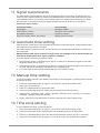
11 Signal transmission
The base station will automatically connect to the outdoor sensor. If the battery is changed, the con-
nection must be made manually by pressing the [SENSOR] button at the base station and then press-
ing the [RESET] button on the sensor with a pointed object to manually search for the sensor. When
the connection is successful, the sensor signal strength indicator will be shown on the display.
Connection status display:
Connection status Screen display
Good signal Reception symbol
Searching for a sensor Reception symbol flashes
No signal for 48 hours Er' (Error) is shown
Sensor low battery status, good signal Battery symbol is shown
12 Automatic time setting
After the power is restored, the unit automatically searches for the radio signal. It takes approximately
3-8 minutes for this process to complete.
If the radio signal is received correctly, the date and time are set automatically and the reception sym-
bol is displayed.
NOTICE!During radio signal reception (every 6 hours), the backlight is set to dimmed mode and
returned to normal mode when signal reception is complete.
If no radio signal is received, proceed as follows:
1. Press the RCC button on the base unit for approx. 8 seconds to deactivate reception of the radio
signal (the display shows "OFF").
2. Press the RCC button on the base unit for approx. 8 seconds to activate reception of the radio sig-
nal ("ON" appears in the display). Reception is now initialised again.
3. If no radio signal is still received, the time setting must be made manually.
13 Manual time setting
To set the time/date manually, first disable the reception of the time signal by pressing the RCC button
for about 8 seconds.
1. Press the CLOCK-SET button for approx. 3 seconds to enter the time setting mode.
2. Digits to be set are flashing.
3. Press UP or DOWN button to change the value.
4. Press the CLOCK-SET button to confirm the entry and move to the next setting.
5. Settings order: 12/24-hour mode > Hours > Minutes > Seconds > Year > M> Day > Time offset >
Language > Daylight saving time Auto/off
6. Finally, press the CLOCK-SET button to save the settings and exit the setting mode.
14 Time zone setting
To set a different time zone, proceed as follows:
1. Press the CLOCK-SET button for approx. 3 seconds to enter the time setting mode.
2. Press the CLOCK-SET button several times until the display shows 00 Hr time offset.
3. Press UP or DOWN button to select the desired time deviation in hours (-23 up to +23 hours).
4. Press the CLOCK-SET button for approx. 3 seconds to confirm the selected time deviation.

12 / 44
15 Setting Daylight Saving Time (DST)
To set a different time zone, proceed as follows:
1. Press the TIME button for about 3 seconds to enter the time setting mode.
2. Press the TIME button repeatedly until the daylight saving time (DST) setting flashes on the dis-
play.
3. Press the UP or DOWN button to select between AUTO (summer time on) and OFF (summer time
off).
4. Press the TIME button for about 3 seconds to confirm the setting.
16 Alarm setting
Turn on/off Alarm clock (and Ice Alert function)
1. Press ALARM button to show the alarm time.
2. Press the ALARM button again to activate the alarm.
3. Press the ALARM button one more time to activate the alarm with ice alert.
4. With activated ice alert, the alarm will sound 30 minutes earlier if outside temperature is below -3°
C.
5. To disable the alarm and ice alert, press the ALARM button until the alarm icons disappear.
Set Alarm time
6. Press and hold ALARM button for approx. 3 seconds to enter the alarm time setting mode.
7. Digits to be set are flashing.
8. Press UP or DOWN button to change the value.
9. Press ALARM button to confirm and continue to the next setting.
10. Settings order: Hours > Minutes
11. Finally press the ALARM button to save the settings and exit the setting mode.
17 Snooze function
1. When the alarm sound starts, press the ALARM/SNOOZE button to activate the Snooze function.
The Alarm will sound again after 5 minutes.
2. When the alarm sound starts, press the ALARM button or press and hold the ALARM/SNOOZE
button for approx. 3 seconds, to stop the alarm.
3. The alarm will be turned off automatically if no button is pressed within 2 minutes.
18 Receiving measurements automatically
Once power is restored, the base station will begin to display indoor readings and the first readings re-
ceived from the outdoor sensor will be displayed within approximately 3 minutes of commissioning.
If no signal is received, proceed as follows:
Press the SENSOR button for approx. 2 seconds to initiate the reception of the measured values
again.

13 / 44
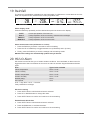
19 Rainfall
The amount of precipitation is displayed on the base station in millimeters or inches that has accumu-
lated over a period of time, based on the current precipitation rate.
Rainfall rate Daily rainfall Weekly rainfall Monthly rainfall
Select display mode
Press the RAIN key repeatedly until the desired time period is shown on the display:
RATE Current precipitation of the last hour
DAILY Total precipitation of the current day, measured from midnight
WEEKLY Total precipitation of the current week
MONTHLY Total precipitation of the current month
Select measurement unit (millimeters or inches)
1. Press the RAIN key for about 3 seconds to enter unit setting.
2. Press the UP or DOWN key to toggle between mm (millimeters) and in (inches).
3. Finally, press the RAIN key to save the settings and exit settings mode.
NOTICE!The readings are automatically updated every 6 minutes.
20 HI/LO Alert
HI/LO alert are used to alert you of certain weather conditions. Once activated, an alarm sound is
triggered and the alert icon flashes as soon as a set value is reached. Supported areas and alarm
types:
Area Type of alert available
Indoor temperature HI AL / LO AL
Indoor humidity HI AL / LO AL
Outdoor temperature HI AL / LO AL
Outdoor humidity HI AL / LO AL
Rainfall (daily) HI AL*
Wind speed HI AL
HI AL = High alert / LO AL = Low alert
*Daily rainfall since midnight
HI/LO alert setting
1. Press ALERT button until the desired area is selected.
2. Press UP or DOWN button to change the value.
3. Press ALERT button to confirm and continue to the next setting.
Enable/Disable HI/LO Alert
4. Press ALERT button until the desired area is selected.
5. Press ALARM button, to activate the alarm.
6. Press ALERT button to confirm and continue to the next setting.

14 / 44
Note:
7. The unit will automatically exit setting mode in 5 seconds if no button is pressed.
8. When ALERT alarm is on, the area and type of alarm that triggered the alarm will be flashing and
the alarm will sound for 2 minutes.
9. Press SNOOZE/LIGHT button when alarm sounds to interrupt the alarm. The alarm will then start
again after 2 minutes.
Data clearing
10. Press and hold HISTORY button for approx. 3 seconds.
11. Press UP or DOWN button to choose YES or NO.
12. Press HISTORY button to confirm. This will clear out any rainfall data recorded before.
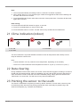
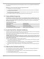
21 Clima indication (indoor)
123
1 too cold 2 comfortable
3 too warm
The clima indication is a pictorial indication based on indoor air temperature and humidity in an at-
tempt to determine comfort level.
Note:
• Comfort indication can vary under the same temperature, depending on the humidity.
• There is no comfort indication when temperature is below 0° C (32° F) or over 60° C (140° F)
22 Data clearing
During installation of the outdoor sensor, the sensor could have been triggered, resulting in erroneous
rainfall and wind measurements. After the installation user may clear all the erroneous data from the
main unit without a need to reset the clock and re-establish pairing. Simply press and hold the HIS-
TORY button for 10 seconds. This will clear out any data recorded before.
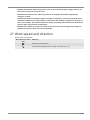
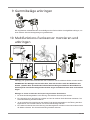
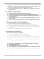
23 Pointing the sensor to the south
The sensor is calibrated to be pointing to North by default. However, in some cases, users may wish
to install the product with the arrow pointing towards the South, especially for people living in the
Southern hemisphere (e.g. Australia, New Zealand).

15 / 44
12
1 Northern hemisphere 2 Southern hemisphere
1. First install the outdoor sensor with its arrow pointing to the south. Please refer to "Installation"
chapter for mounting details.
2. Press and hold the WIND button for approx. 8 seconds until the upper part (northern hemisphere)
of the compass rose is blinking.
3. Press the UP or DOWN button to change to lower part (southern hemisphere).
4. Press the WIND button to confirm and exit.
Note:
Changing the hempisphere setting will automatically switch the direction of the moon phase on the dis-
play.
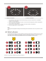
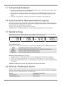
24 Moon phases
In the Northern hemisphere, the moon waxes from the right. Hence the sun-lit area of the moon moves
from right to left in the Northern hemisphere, while in the Southern hemisphere, it moves from left to
right. Below are the 2 tables which illustrate how the moon will appear on the main unit.
A
1
2
3
4
5
6
7
8
B
1
2
3
4
5
6
7
8
Illustration3: (A) Northern hemisphere, (B) Southern hemisphere

16 / 44
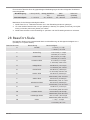
1 New moon 2 Waxing crescent
3 First quarter 4 Waxing gibbous
5 Full moon 6 Waning gibbous
7 Third quarter 8 Waning crescent
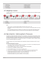
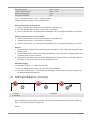
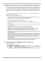
25 Weather trend
A weather trend for the next 12-24 hours is calculated from the measured values and displayed graph-
ically as follows:
123456
1 Sunny 2 Partly cloudy
3 Cloudy 4 Rain
5 Rain/storm 6 Snow
Note:
• The accuracy of a pressure-based weather forecast is about 70% to 75%.
• The weather forecast is intended for the next 12 hours and does not necessarily reflect the current
situation.
• The snow weather forecast is not based on air pressure, but on the outdoor temperature. When
the outdoor temperature is below -3°C (26°F), the snow symbol appears on the LCD display.
26 Barometric / Atmospheric Pressure
Atmospheric pressure (hereinafter referred to as "air pressure") is the pressure at any place on earth
caused by the weight of the layer of air above it. Air pressure is proportional to average pressure and
decreases gradually with altitude. Meteorologists use barometers to measure air pressure. Because
the weather is highly dependent on changes in air pressure, it is possible to make a weather forecast
from the measured changes in air pressure.
In normal display mode, press the BARO button repeatedly to display the desired unit (hPa, inHg or
mmHg).
Set relative atmospheric pressure
1. Find out the relative air pressure value for your location (or as close to it as possible) through the
local weather service, the Internet or other sources.
2. Press the BARO button for approx. 3 seconds until ABS or REL flashes.
3. Press the UP or DOWN key until REL flashes.
4. Press the BARO button to move to the next setting value.
5. Press the UP or DOWN key to change the REL value (according to the researched value).
6. Finally, press the CLOCK-SET button to save the settings and exit the setting mode.
•NOTICE!ABS: Absolute air pressure at your current location
•NOTICE!REL: Relative air pressure based on sea level (N.N.)

17 / 44
•NOTICE!The default relative air pressure value is 1013 mbar/hPa (29.91 inHg), which is rel-
ative to the average air pressure value.
•NOTICE!If the value for the relative air pressure is changed, the weather displays also
change as a result.
•NOTICE!The built-in barometer registers changes in absolute air pressure caused by the en-
vironment. Based on the collected data, a forecast for the weather conditions in the next 12
hours can be made. The weather indicators change according to the determined absolute air
pressure after only one hour of operation.
•NOTICE!The relative air pressure is based on sea level, but it also changes with changes in
absolute air pressure after one hour of operation.
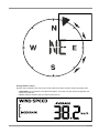
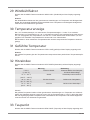
27 Wind speed and direction
Reading the wind direction
Wind direction indic-
ator
Meaning
Real-time wind direction
Wind directions appeared in the last 5 minutes (max. 6)

18 / 44
Select display mode
Press the WIND button several times until the desired rate is displayed:
•AVERAGE: average of all wind speed numbers recorded in the previous 30 seconds
•GUST: highest wind speed (gust) recorded from last reading

19 / 44
The wind level provides a quick reference on the wind condition and is indicated by a series of text
icons:
Wind level LIGHT MODERATE STRONG STORM
Speed 1 – 19 km/h 20 – 49 km/h 50 – 88 km/h > 88 km/h
Select wind speed unit
1. Press the WIND button for approx. 3 seconds to enter the setting mode.
2. Press the UP or DOWN button to change the unit between mph (miles per hour), m/s (miles per
second), km/h (kilometer per hour) or knots.
3. Press the WIND button to save the settings and exit the setting mode.
28 Beaufort scale
The Beaufort scale is an international scale of wind velocities from 0 (calm) to 12 (Hurricane force).
Beaufort number Description Speed
0calm < 1 km/h | < 1 mph
< 1 knots | < 0.3 m/s
1light air 1.1-5.5 km/h | 1-3 mph
1-3 knots | 0.3-1.5 m/s
2light breeze 5.6-11 km/h | 4-7 mph
1-3 knots | 0.3-1.5 m/s
3gentle breeze 12-19 km/h | 8-12 mph
7-10 knots | 3.5-5.4 m/s
4moderate breeze 20-28 km/h | 13-17 mph
11-16 knots | 5.5-7.9 m/s
5fresh breeze 29-38 km/h | 18-24 mph
17-21 knots | 8.0-10.7 m/s
6strong gale 39-49 km/h | 25-30 mph
22-27 knots | 10.8-13.8 m/s
7high wind 50-61 km/h | 31-38 mph
28-33 knots | 13.9-17.1 m/s
8gale 62-74 km/h | 39-46 mph
34-40 knots | 17.2-20.7 m/s
9strong gale 75-88 km/h | 47-54 mph
41-47 knots | 20.8-24.4 m/s
10 storm 89-102 km/h | 55-63 mph
48-55 knots | 24.5-28.4 m/s
11 violent storm 103-117 km/h | 64-73 mph
56-63 knots | 28.5-32.6 m/s
12 hurricane force > 118 | > 74 mph
> 64 knots | 32.7 m/s
29 Wind chill factor
Press the INDEX button several times until WIND CHILL is displayed.

20 / 44
Note:
The wind chill factor is based on the common effects of temperature and wind speed.The displayed
wind chill is calculated solely from temperature and wind speed and is measured by the outdoor
sensor.
30 Temperature display
Move the °C/°F switch to toggle between °C and °F temperature display.
When temperatures of -40° C or below are reached, the information "LO" is output for the respective
range, when temperatures of over 70° C or above are reached, the information "HI" is output. The
measurable temperature range has been exceeded or fallen below.
When returning to a measurable temperature range, the appropriate temperature is displayed again.
31 Feels like temperature
Press the INDEX button repeatedly until FEELS LIKE appears on the display.
Note:
The feels like temperature indicates the temperature value according to the personal temperature per-
ception.
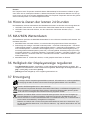
32 Heat index
Press the INDEX button several times until HEAT INDEX is displayed.
Heat index Warning Meaning
> 55° C
(> 130° F)
Extreme danger Strong risk of dehydration / sun
stroke
41° C – 54° C
(106° F – 129° F)
Danger Heat exhaustion likely
33° C – 40° C
(91° F – 105° F)
Extreme caution Possibility of dehydration
27° C – 32° C
(80° F – 90° F)
Caution Possibility of heat exhaustion
Notice:
The perceived temperature is based on the common effects of temperature and humidity. Heat index
is only calculated when room temperature is at 27° (80° F) or higher. The displayed perceived temper-
ature is calculated solely from temperature and humidity and is measured by the outdoor sensor.
33 Dew point
Press the INDEX button several times until DEW POINT is displayed.
Note:
The dew point is the temperature below which the water vapor in air at constant barometric pressure
condenses into liquid water at the same rate at which it evaporates. The condensed water is called
dew when it forms on a solid surface. The dewpoint temperature is calculated from the indoor temper-
ature and humidity measured at the main unit.
Seite laden ...
Seite laden ...
Seite laden ...
Seite laden ...
Seite laden ...
Seite laden ...
Seite laden ...
Seite laden ...
Seite laden ...
Seite laden ...
Seite laden ...
Seite laden ...
Seite laden ...
Seite laden ...
Seite laden ...
Seite laden ...
Seite laden ...
Seite laden ...
Seite laden ...
Seite laden ...
Seite laden ...
Seite laden ...
Seite laden ...
Seite laden ...
-
 1
1
-
 2
2
-
 3
3
-
 4
4
-
 5
5
-
 6
6
-
 7
7
-
 8
8
-
 9
9
-
 10
10
-
 11
11
-
 12
12
-
 13
13
-
 14
14
-
 15
15
-
 16
16
-
 17
17
-
 18
18
-
 19
19
-
 20
20
-
 21
21
-
 22
22
-
 23
23
-
 24
24
-
 25
25
-
 26
26
-
 27
27
-
 28
28
-
 29
29
-
 30
30
-
 31
31
-
 32
32
-
 33
33
-
 34
34
-
 35
35
-
 36
36
-
 37
37
-
 38
38
-
 39
39
-
 40
40
-
 41
41
-
 42
42
-
 43
43
-
 44
44


Bresser 7002525 Bedienungsanleitung
- Kategorie
- Wetterstationen
- Typ
- Bedienungsanleitung
- Dieses Handbuch ist auch geeignet für
in anderen Sprachen
- English: Bresser 7002525 Owner's manual
Verwandte Papiere
-
Bresser 7902525 Bedienungsanleitung
-
Bresser 9080500 - Colour Weather Center 5-in-1 National Geographic Bedienungsanleitung
-
-
-
-
Bresser 7902580 Bedienungsanleitung
-
Bresser 7002510 Bedienungsanleitung