
Bedienungsanleitung
Operation Manual
Innovation,
die bewegt!
AC
~
DC
=
5216
Langsamfahrwiderstand
Slow speed resistor
1. Wichtige Hinweise ........................ 2
2. Einleitung ...................................... 2
3. Überlast ........................................ 2
4. Langsamfahrabschnitt .................. 3
5. Anschluss ..................................... 3
6. Montage ........................................ 3
7. Technische Daten ......................... 3
Abbildungen .................................. 6
1. Important information .................... 4
2. Introduction ................................... 4
3. Overload ....................................... 4
4. Slow drive section ......................... 4
5. Connection ................................... 5
6. Mounting ....................................... 5
7. Technical data ............................... 5
Figures .......................................... 6

2
DE
1. Wichtige Hinweise
Bitte lesen Sie vor der ersten Anwendung des Produktes bzw. dessen Einbau diese Bedienungsanleitung
aufmerksam durch. Bewahren Sie diese auf, sie ist Teil des Produktes.
1.1 Sicherheitshinweise
Vorsicht:
Für die Montage sind Werkzeuge nötig.
Stromschlaggefahr!
Die Anschlussdrähte niemals in eine Steckdose einführen! Verwendetes Versorgungsgerät (Transformator,
Netzteil) regelmäßig auf Schäden überprüfen. Bei Schäden am Versorgungsgerät dieses keinesfalls
benutzen!
Alle Anschluss- und Montagearbeiten nur bei abgeschalteter Betriebsspannung durchführen!
Ausschließlich nach VDE/EN gefertigte Modellbahntransformatoren verwenden!
Stromquellen unbedingt so absichern, dass es bei einem Kurzschluss nicht zum Kabelbrand kommen kann.
1.2 Das Produkt richtig verwenden
Dieses Produkt ist bestimmt:
- Zum Einbau in Modelleisenbahnanlagen und Dioramen.
- Zum Anschluss an einen Modellbahntransformator (z. B. Art. 5200) bzw. an einer Modellbahnsteuerung
mit zugelassener Betriebsspannung.
- Zum Betrieb in trockenen Räumen.
Jeder darüber hinausgehende Gebrauch gilt als nicht bestimmungsgemäß. Für daraus resultierende
Schäden haftet der Hersteller nicht.
1.3 Packungsinhalt überprüfen
Kontrollieren Sie den Lieferumfang auf Vollständigkeit:
- Langsamfahrwiderstand, Art. 5216
- 2 Schrauben
- 4 Stecker
- Anleitung
2. Einleitung
Der Langsamfahrwiderstand wurde speziell für den Einsatz auf Modelleisenbahnanlagen entwickelt. In
diesem Zusammenhang sei insbesondere auf den integrierten Überlast-Schutz mit Anzeige hingewiesen.
Die Digitaltauglichkeit ist eingeschränkt, da moderne Lokdecoder mit Lastregelung den Widerstand ohne
Abbremsen überfahren. Der Anschluss ist kinderleicht – der Baustein wird einfach in die Fahrstromzufüh-
rung zum Langsamfahrabschnitt eingefügt.
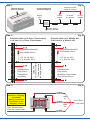
Je nach gewünschter bzw. erforderlicher Geschwindigkeitsreduzierung im Langsamfahrbereich ist die
Einstellung eines individuellen Widerstandswertes erforderlich (Abb. 1). Diese Einstellung erfolgt über die
Belegung der Anschlussbuchsen.
In den Anschlussplänen dieser Anleitung finden Sie häufig das oben stehende Symbol. Es kennzeichnet
eine Leitungsverbindung. Die sich hier kreuzenden Leitungen müssen an einer beliebigen Stelle ihres
Verlaufs elektrisch leitend miteinander in Verbindung stehen. Der Verbindungspunkt muss also nicht
exakt an der eingezeichneten Stelle sitzen, sondern kann z. B. zu einem Stecker, welcher sich an einer
der kreuzenden Leitungen befindet, verlagert werden.

3
3. Überlast
Der Langsamfahrwiderstand, Art. 5216 besitzt eine Überlastschutzabschaltung. Im Falle eines Ansprechens des
Überlastschutzes – erkennbar am Leuchten der roten Anzeige – ist zunächst die Ursache der Überlastung (z. B.
entgleister Zug auf den Schienen) zu beseitigen und die Fahrspannung abzuschalten. Nach einer Abkühlphase
von ca. 1 – 2 Minuten ist der Langsamfahrwiderstand wieder einsatzbereit.
4. Langsamfahrabschnitt
Wir haben hier den Abschnitt hinter einem Signal als Langsamfahrabschnitt eingerichtet (Abb. 2). Dieser
Abschnitt kann auch Weichen enthalten. Eine am Lichtsignal angezeigte Langsamfahrt (Hp2) gilt schließlich
nicht (nur) für den Halteabschnitt unmittelbar vor dem Signal sondern insbesondere für den Bereich
dahinter. Mehrere der umseitig abgebildeten Schaltungen können auf einen Weichenbereich gemeinsam
wirken, so dass von derart abgesicherten Bahnhofsgleisen über die Weichenstraße langsam ein- oder
ausgefahren werden kann. Es ist nur ein Langsamfahrwiderstand erforderlich!
5. Anschluss
1. Schließen Sie den Fahrstrom ausschließlich an die mit „Eingang“ beschriftete Buchse an.
2. Der Ausgang zur Schiene kann nun wahlweise an den Buchsen “10 Ohm”, “20 Ohm” oder ”30 Ohm”
abgegriffen werden (Abb. 3). Je höher der Ohm-Wert, desto geringer ist die Geschwindigkeit des Zuges.
Der richtige Wert ist individuell zu ermitteln.
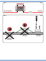
3. Den Zwischenwert “15 Ohm” (rot beschriftet) erhalten Sie, wenn für den Anschluss der Schiene die
“20 Ohm”-Buchse verwendet wird und gleichzeitig eine Verbindung von der “10 Ohm”-Buchse zur ”30
Ohm”-Buchse gesteckt wird (Abb. 4).
6. Montage
Die Befestigung des Bausteins erfolgt mit den beiliegenden Schrauben. Da der Langsamfahrwiderstand im
Betrieb heiß werden kann, beachten Sie folgende Hinweise.
Vorsicht!
Lüftungsschlitze nicht abdecken!
Baustein mit nach oben zeigenden Lüftungsschlitzen montieren, also keine Über-Kopf-Montage direkt
unter der Anlage (Abb. 5).
Keine leicht entzündlichen Materialien in unmittelbarer Nähe anbringen bzw. deponieren.
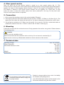
7. Technische Daten
Betriebsspannung: max. 24 V ~/=
Verlustleistung max. 5 W
Einstellbare Widerstandswerte: 10 Ohm
15 Ohm
20 Ohm
30 Ohm
Gewicht: 25 g
Abmessungen: L 5,4 x B 3,4 x H 2,2 cm
Änderungen vorbehalten. Keine Haftung für Druck-
fehler und Irrtümer.
Die aktuelle Version der Anleitung finden Sie auf
der Viessmann Homepage unter der Artikelnummer.
Entsorgen Sie dieses Produkt nicht über
den (unsortierten) Hausmüll, sondern
führen Sie es der Wiederverwertung zu.

4
1. Important information
Please read this manual completely and attentively before using the product for the first time. Keep this
manual. It is part of the product.
1.1 Safety instructions
Caution:
For installation tools are required.
Electrical hazard!
Never put the connecting wires into a power socket! Regularly examine the transformer for damage. In
case of any damage, do not use the transformer.
Make sure that the power supply is switched off when you mount the device and connect the cables!
Only use VDE/EN tested special model train transformers for the power supply!
The power sources must be protected to avoid the risk of burning cables.
1.2 Using the product for its correct purpose
This product is intended:
- For installation in model train layouts and dioramas.
- For connection to an authorized model train transformer (e. g. item 5200) or a digital command station.
- For operation in dry rooms only.
Using the product for any other purpose is not approved and is considered inappropriate. The manufac-
turer is not responsible for any damage resulting from the improper use of this product.
1.3 Checking the package contents
Check the contents of the package for completeness:
- Slow speed resistor, item 5216
- 2 Screws
- 4 Plugs
- Manual
EN
2. Introduction
The slow speed resistor, item 5216 has been especially developed for the use on model train layouts. We
want to your special attention to the integrated overload protection with indicator. The digital suitability
is limited, as modern locomotive decoders with load on track pass the resistor without braking. It is quite
easy to connect the module. You have to insert it only into the tracking current supply to the track.
You have to choose an individual resistance. The value depends on the necessary driving speed (fig. 1).
You can select the value by using the different sockets of the module.
In the connection diagrams of this instruction you can often see the above shown symbol. It describes a
wire connection. The wires which are crossing themselves have to be connected electrically at any point
on their way. So the connection point needs not to be exactly at the shown location. It can be moved e. g.
to a plug which is connected to one of the crossing wires.
3. Overload
The slow speed resistor, item 5216 has got an overload protection unit. If an overload is detected, the red
light turns on. First, you have to remove the cause of the overload and switch off the driving voltage. After
a cooling time of 1 – 2 minutes, the slow speed resistor is ready for use again.

5
4. Slow speed section
Here we have set up the section behind a signal as a slow speed section (fig. 2). This
section can also contain points. A slow speed section indicated by the colour light signal (Hp2) finally applies
applies not (only) to the stopping section directly in front of the signal, but especially to the sec-
tion behind it. Several of the circuits shown overleaf can act together on a point area, so that
trains can enter or leave the station slowly from tracks protected in this way via the point road.
Only one slow speed resistor is required!
5. Connection
1. Only connect the tracking current to the socket labelled “Eingang”.
2. The output to the track now can be taken from the sockets “10 Ohm”, “20 Ohm“ or “30 Ohm“ (fig. 3). The
higher the Ohm value, the slower the train will be. You have to determine individual the correct value.
3. You will get a resistance of 15 Ohms (red box print), if you use the “20 Ohm“ socket and make an
additional connection from the ”10 Ohm” socket to the “30 Ohm” socket (fig. 4).
6. Mounting
Fasten the module with the enclosed screws. During operation the resistor can get hot. Please observe
the following notes.
Caution!
Do not cover the ventilation slots!
Mount the module with the ventilation slots on the top. Do not mount it overhead (fig. 5).
Never mount or store any inflammable materials in direct nearness of the resistor.
7. Technical data
Operating voltage: max. 24 V AC/DC
Power dissipation: max. 5 W
Selectable resistance value: 10 Ohm
15 Ohm
20 Ohm
30 Ohm
Weight: 25 g
Dimensions: L 5.4 x W 3.4 x H 2.2 cm
Subject to change without prior notice. No liability
for mistakes and printing errors.
You will find the latest version of the manual on the
Viessmann website using the item number.
Do not dispose of this product through
(unsorted) domestic waste, supply it to
recycling instead.

6
Überlast
10 Ohm 30 Ohm
Eingang 15/20 Ohm
5216
Langsamfahrwiderstand
Überlast-Anzeige
Overload indicator
Brücke für 15 Ohm
10 Ohm 15 / 20 Ohm 30 Ohm
10 Ohms 15 / 20 Ohms 30 Ohms
Überlast-Anzeige
Overload indicator
Bridge for 15 Ohms
Überlast-
schutz
Overload
protection
Eingang
Input
Funktionsdiagramm
Functional diagram
Fig. 1
Abb. 1
Zweileiter Gleis (z. B. Roco, Fleischmann)
2 rail track (e. g. Roco, Fleischmann )
Dreileiter Gleis (z. B. Märklin H0)
3 rail track (e. g. Märklin H0)
Langsamfahrabschnitt
Slow speed section
z. B. Art.-Nr. 4011
e. g. item-No. 4011
Halteabschnitt
Stop section
Trennstellen
Insulations
Länge bitte
empirisch ermitteln.
Please determine
this length empirically.
Langsamfahrabschnitt
Slow speed section
Halteabschnitt
Stop section
Mittelleiter-Trennstellen
Third rail insulations
z. B. Art.-Nr. 4011
e. g. item-No. 4011
Fig. 2
Abb. 2
Transformator immer
an Buchse “Eingang”
anschließen.
Always connect the
transformer to the
“Eingang” socket!
Vom Transformator
From the transformer
10 Ohm
10 Ohms
30 Ohm
30 Ohms
20 Ohm
20 Ohms
oder
or
oder
or
Zum Gleis
To the track
Fig. 3
Abb. 3

7
15 Ohm
15 Ohms
Zum Gleis
To the track
Vom Transformator
From the transformer
Drahtbrücke
Wire bridge
Fig. 4
Abb. 4
Falsch!
Wrong!
Falsch!
Wrong!
Richtig!
Correct!
Fig. 5
Abb. 5

Modellbauartikel, kein Spielzeug! Nicht geeignet für
Kinder unter 14 Jahren! Anleitung aufbewahren!
Model building item, not a toy! Not suitable for children
under the age of 14 years! Keep these instructions!
Ce n’est pas un jouet! Ne convient pas aux enfants de moi-
ns de 14 ans! Conservez cette notice d’instructions!
Não é um brinquedo! Não aconselhável para menores de
14 anos! Conservar o manual de instruções!
Modelbouwartikel, geen speelgoed! Niet geschikt voor
kinderen onder 14 jaar! Gebruiksaanwijzing bewaren!
Articolo di modellismo, non è un giocattolo! Non adatto
a bambini al di sotto dei 14 anni! Conservare istruzioni per
l’uso!
Artículo para modelismo ¡No es un juguete! No
recomendado para menores de 14 años! Conserva las
instrucciones de servicio!
DE
EN
FR
NL
IT
ES
PT
Made in Europe
Viessmann
Modelltec
hnik GmbH
Bahnhofstraße 2a
D - 35116 Hatzfeld-Reddighausen
+49 6452 9340-0
www.viessmann-modell.de
8
98032
Stand 03/fa
08/2022
Ho/Kf
-
 1
1
-
 2
2
-
 3
3
-
 4
4
-
 5
5
-
 6
6
-
 7
7
-
 8
8


in anderen Sprachen
- English: Viessmann 5216 Owner's manual
Verwandte Artikel
-
Viessmann 5216 Bedienungsanleitung
-
-
-
-
-
-
-
-
-