
Bedienungsanleitung
Operation Manual
AC
~
DC
=
5216
Langsamfahrwiderstand
5216
Slow speed resistor
1. Wichtige Hinweise ...................................... 2
2. Einleitung .................................................... 3
3. Überlast ....................................................... 3
4. Langsamfahrabschnitt ................................ 4
5. Anschluss ................................................... 5
6. Montage ...................................................... 6
7. Technische Daten ....................................... 6
1. Important information .................................. 2
2. Introduction ................................................. 3
3. Overload ..................................................... 3
4. Slow drive section ....................................... 4
5. Connection ................................................. 5
6. Mounting ..................................................... 6
7. Technical data ............................................. 6

2
DE EN
1. Wichtige Hinweise
Bitte lesen Sie vor der ersten Anwendung des
Produktes bzw. dessen Einbau diese Bedienungs-
anleitung aufmerksam durch. Bewahren Sie diese
auf, sie ist Teil des Produktes.
1.1 Sicherheitshinweise
Vorsicht:
Für die Montage sind Werkzeuge nötig.
Stromschlaggefahr!
Die Anschlussdrähte niemals in eine Steckdo-
se einführen! Verwendetes Versorgungsgerät
(Transformator, Netzteil) regelmäßig auf Schäden
überprüfen. Bei Schäden am Versorgungsgerät
dieses keinesfalls benutzen!
Alle Anschluss- und Montagearbeiten nur bei ab-
geschalteter Betriebsspannung durchführen!
Ausschließlich nach VDE/EN-gefertigte Modell-
bahntransformatoren verwenden!
Stromquellen unbedingt so absichern, dass es
bei einem Kurzschluss nicht zum Kabelbrand
kommen kann.
1.2 Das Produkt richtig verwenden
Dieses Produkt ist bestimmt:
- Zum Einbau in Modelleisenbahnanlagen und
Dioramen.
- Zum Anschluss an einen Modellbahntrans-
formator (z. B. Art.-Nr. 5200) bzw. an einer
Modellbahnsteuerung mit zugelassener
Betriebsspannung.
- Zum Betrieb in trockenen Räumen.
Jeder darüber hinausgehende Gebrauch gilt als
nicht bestimmungsgemäß. Für daraus resultieren-
de Schäden haftet der Hersteller nicht.
1.3 Packungsinhalt überprüfen
Kontrollieren Sie den Lieferumfang auf
Vollständigkeit:
- Langsamfahrwiderstand, Art.-Nr. 5216
- 2 Schrauben
- 4 Stecker
- Anleitung
1. Important information
Please read this manual completely and attentive-
ly before using the product for the first time. Keep
this manual. It is part of the product.
1.1 Safety instructions
Caution:
For installation tools are required.
Electrical hazard!
Never put the connecting wires into a power
socket! Regularly examine the transformer for
damage. In case of any damage, do not use the
transformer.
Make sure that the power supply is switched
off when you mount the device and connect the
cables!
Only use VDE/EN tested special model train
transformers for the power supply!
The power sources must be protected to pre-
vent the risk of burning cables.
1.2 Using the product for its correct purpose
This product is intended:
- For installation in model train layouts and
dioramas.
- For connection to an authorized model train
transformer (e. g. item-No. 5200) or a digital
command station.
- For operation in dry rooms only.
Using the product for any other purpose is not
approved and is considered incorrect. The manu-
facturer is not responsible for any damage
resulting from the improper use of this product.
1.3 Checking the package contents
Check the contents of the package for
completeness:
- Slow speed resistor, item-No. 5216
- 2 Screws
- 4 Plugs
- Manual

3
Überlast
10 Ohm
30 Ohm
Eingang
15/20 Ohm
5216
Langsamfahrwiderstand
Überlast-Anzeige
Overload indicator
Brücke für 15 Ohm
10 Ohm 15 / 20 Ohm 30 Ohm
10 Ohms 15 / 20 Ohms 30 Ohms
Überlast-Anzeige
Overload indicator
Bridge for 15 Ohms
Überlast-
schutz
Overload
protection
Eingang
Input
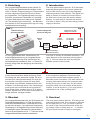
Funktionsdiagramm
Functional diagram
Fig. 1
Abb. 1
2. Einleitung
Der Langsamfahrwiderstand wurde speziell für
den Einsatz auf Modelleisenbahnanlagen entwi-
ckelt. In diesem Zusammenhang sei insbesondere
auf den integrierten Überlast-Schutz mit Anzei-
ge hingewiesen. Die Digitaltauglichkeit ist einge-
schränkt, da moderne Lokdecoder mit Lastrege-
lung den Widerstand ohne Abbremsen überfah-
ren. Der Anschluss ist kinderleicht – der Baustein
wird einfach in die Fahrstromzuführung zum Lang-
samfahrabschnitt eingefügt.
2. Introduction
The slow speed resistor item-No. 5216 has been
especially developed for the use on model train
layouts. We want to point out to the integrated
overload protection with indicator. The digital suit-
ability is limited, as modern locomotive decod-
ers with load on track pass the resistor without
braking. It is quite easy to connect the module.
You have to insert it only into the tracking current
supply to the track.
Je nach gewünschter bzw. erforderlicher Ge-
schwindigkeitsreduzierung im Langsamfahrbe-
reich ist die Einstellung eines individuellen Wi-
derstandswertes erforderlich (Abb. 1). Diese Ein-
stellung erfolgt über die Belegung der Anschluss-
buchsen.
In den Anschlussplänen dieser Anleitung finden
Sie häufig das oben stehende Symbol. Es kenn-
zeichnet eine Leitungsverbindung. Die sich hier
kreuzenden Leitungen müssen an einer belie-
bigen Stelle ihres Verlaufs elektrisch leitend mit-
einander in Verbindung stehen. Der Verbindungs-
punkt muss also nicht exakt an der eingezeich-
neten Stelle sitzen, sondern kann z. B. zu einem
Stecker, welcher sich an einer der kreuzenden Lei-
tungen befindet, verlagert werden.
3. Überlast
Der Langsamfahrwiderstand Art.-Nr. 5216 besitzt eine
Überlastschutzabschaltung. Im Falle eines Anspre-
chens des Überlastschutzes – erkennbar am Leuch-
ten der roten Anzeige – ist zunächst die Ursache der
Überlastung (z. B. entgleister Zug auf den Schienen)
zu beseitigen und die Fahrspannung abzuschalten.
Nach einer Abkühlphase von ca. 1 – 2 Minuten ist der
Langsamfahrwiderstand wieder einsatzbereit.
You have to choose an individual resistance. The
value depends on the necessary driving speed
(fig. 1). You can select the value by using the
different sockets of the module.
In the connection diagrams of this instruction
you can often see the above shown symbol. It
describes a wire connection. The wires which are
crossing themselves have to be connected elec-
trically at any point on their way. So the connec-
tion point needs not to be exactly at the shown
location. It can be moved e. g. to a plug which is
connected to one of the crossing wires.
3. Overload
The slow speed resistor item-No. 5216 has got an
overload protection unit. If an overload is detected
the red light turns on. First, you have to remove
the cause of the overload and switch off the driv-
ing voltage. After a cooling time of 1 – 2 minutes,
the slow speed resistor is ready for use again.

4
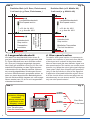
Transformator immer
an Buchse “Eingang”
anschließen.
Always connect the
transformer to the
“Eingang” socket!
Vom Transformator
From the transformer
10 Ohm
10 Ohms
30 Ohm
30 Ohms
20 Ohm
20 Ohms
oder
or
oder
or
Zum Gleis
To the track
Fig. 3
Abb. 3
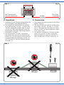
4. Langsamfahrabschnitt
Wir haben hier den Abschnitt hinter einem Si-
gnal als Langsamfahrabschnitt eingerichtet (Abb.
2). Dieser Abschnitt kann auch Weichen enthal-
ten. Eine am Lichtsignal angezeigte Langsam-
fahrt (Hp2) gilt schließlich nicht (nur) für den Hal-
teabschnitt unmittelbar vor dem Signal sondern
insbesondere für den Bereich dahinter. Mehrere
der umseitig abgebildeten Schaltungen können
auf einen Weichenbereich gemeinsam wirken, so
dass von derart abgesicherten Bahnhofsgleisen
über die Weichenstraße langsam ein- oder ausge-
fahren werden kann. Es ist nur ein Langsamfahr-
widerstand erforderlich!
4. Slow speed section
To install a slow speed section it is necessary to
insulate one conductor of your track from the rest
of the layout as it is shown in the picture below.
Here we have made the area behind a signal as a
slow speed section.This section can contain some
turnouts, too. When the colour light signal displays
“slow speed” (Hp2) then it implies slow speed not
(only) in the stop section in front of the signal but
in particular slow speed behind the signal. Sever-
al of the circuits shown on the next page can act
simultaneously on one turnout section. You need
only one slow speed resistor!
Zweileiter Gleis (z. B. Roco, Fleischmann)
2 rail track (e. g. Roco, Fleischmann )
Dreileiter Gleis (z. B. Märklin H0)
3 rail track (e. g. Märklin H0)
Langsamfahrabschnitt
Slow speed section
z. B. Art.-Nr. 4011
e. g. item-No. 4011
Halteabschnitt
Stop section
Trennstellen
Insulations
Länge bitte
empirisch ermitteln.
Please determine
this length empirically.
Langsamfahrabschnitt
Slow speed section
Halteabschnitt
Stop section
Mittelleiter-Trennstellen
Third rail insulations
z. B. Art.-Nr. 4011
e. g. item-No. 4011
Fig. 2
Abb. 2

5
Falsch!
Wrong!
Falsch!
Wrong!
Richtig!
Correct!
15 Ohm
15 Ohms
Zum Gleis
To the track
Vom Transformator
From the transformer
Drahtbrücke
Wire bridge
Fig. 4
Abb. 4
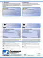
5. Anschluss
1. Schließen Sie den Fahrstrom ausschließlich an
die mit „Eingang“ beschriftete Buchse an.
2. Der Ausgang zur Schiene kann nun wahlwei-
se an den Buchsen “10 Ohm”, “20 Ohm” oder
”30 Ohm” abgegriffen werden (Abb. 3). Je hö-
her der Ohm-Wert, desto geringer ist die Ge-
schwindigkeit des Zuges. Der richtige Wert ist
individuell zu ermitteln.
3. Den Zwischenwert “15 Ohm” (rot beschrif-
tet) erhalten Sie, wenn für den Anschluss der
Schiene die “20 Ohm”-Buchse verwendet wird
und gleichzeitig eine Verbindung von der “10
Ohm”-Buchse zur ”30 Ohm”-Buchse gesteckt
wird (Abb. 4).
Fig. 5
Abb. 5
5. Connection
1. Only connect the tracking current to the socket
labeled “Eingang”.
2. The output to the track now can be taken from
the sockets “10 Ohm”, “20 Ohm“ or “30 Ohm“
(fig. 3). The higher the Ohm value, the slower
the train will be. You have to determine inividu-
al the correct value.
3. You will get a resistance of 15 Ohms (red box
print), if you use the “20 Ohm“ socket and
make an additional connection from the ”10
Ohm” socket to the “30 Ohm” socket (fig. 4).

Modellbauartikel, kein Spielzeug! Nicht geeignet für Kinder
unter 14 Jahren! Anleitung aufbewahren!
Model building item, not a toy! Not suitable for children
under the age of 14 years! Keep these instructions!
Ce n’est pas un jouet. Ne convient pas aux enfants de
moins de 14 ans ! C’est un produit décor! Conservez cette
notice d’instructions!
Não é um brinquedo!Não aconselhável para menores de
14 anos. Conservar a embalagem.
Modelbouwartikel, geen speelgoed! Niet geschikt voor
kinderen onder 14 jaar! Gebruiksaanwijzing bewaren!
Articolo di modellismo, non è un giocattolo! Non adatto
a bambini al di sotto dei 14 anni! Conservare instruzioni
per l’uso!
Artículo para modelismo ¡No es un juguete! No recomen-
dado para menores de 14 años! Conserva las instrucciones
de servicio!
DE
EN
FR
NL
IT
ES
PT
Modelltechnik GmbH
Bahnhofstraße 2a
D - 35116 Hatzfeld-Reddighausen
www.viessmann-modell.de
Made in Europe
Entsorgen Sie dieses Produkt nicht
über den (unsortierten) Hausmüll, son-
dern führen Sie es der Wiederverwer-
tung zu.
Do not dispose this product through
(unsorted) general trash, but supply it
to the recycling.
7. Technical data
Operating voltage: max. 24 V AC/DC
Power dissipation: max. 5 W
Selectable resitance value: 10 Ohm
15 Ohm
20 Ohm
30 Ohm
Weight: 25 g
Dimensions: L 5,4 x W 3,4 x H 2,2 cm
7. Technische Daten
Betriebsspannung: max. 24 V ~/=
Verlustleistung max. 5 W
Einstellbare Widerstandswerte: 10 Ohm
15 Ohm
20 Ohm
30 Ohm
Gewicht: 25 g
Abmessungen: L 5,4 x B 3,4 x H 2,2 cm
6
Die aktuelle Version der Anleitung finden Sie auf der
Viessmann-Homepage unter der Artikelnummer.
The latest version of the manual can be looked up
at the Viessmann homepage entering the item-No.
98032
Stand 02/fa
11/2016
Ho/Pic/Me
6. Montage
Die Befestigung des Bausteins erfolgt mit den beilie-
genden Schrauben. Da der Langsamfahrwiderstand
im Betrieb heiß werden kann, beachten Sie folgende
Hinweise.
Vorsicht!
Lüftungsschlitze nicht abdecken!
Baustein mit nach oben zeigenden Lüftungs-
schlitzen montieren, also keine Über-Kopf-Mon-
tage direkt unter der Anlage (Abb. 5).
Keine leicht entzündlichen Materialien in unmit-
telbarer Nähe anbringen bzw. deponieren.
6. Mounting
Fasten the module with the enclosed screws.
During operation the resistor can get hot. Please
observe the following notes.
Caution!
Don’t cover the ventilation slots!
Mount the module with the ventilation slots on
the top. Do not mount it overhead (fig. 5).
Never mount or store any inflammable materials
in direct nearness of the resistor.
-
 1
1
-
 2
2
-
 3
3
-
 4
4
-
 5
5
-
 6
6


in anderen Sprachen
Verwandte Artikel
-
Viessmann 5216 Bedienungsanleitung
-
-
-
-
-
-
-
-
-
Andere Dokumente
-
Vollmer 41282 Bedienungsanleitung
-
roco 79495 Bedienungsanleitung
-
-
-
-
Peavey CS-G series Benutzerhandbuch
-
Kibri 39721 Bedienungsanleitung
-
-
-