Polk Audio LCi-RTS105 Benutzerhandbuch
- Kategorie
- Lautsprecher
- Typ
- Benutzerhandbuch
Dieses Handbuch ist auch geeignet für

LCi-RTS SERIES
LCi-RTS105
High Performance In-Wall Reference Theater Speakers
Caixas acústicas Reference de alto desempenho para
instalação em parede para sistemas de cinema em casa
Reference-Hochleistungswandlautsprecher
für Heimkinosysteme
Diffusori home theatre Reference ad elevate
prestazioni per installazione in pareti
Altavoces de cine Reference de alto
rendimiento empotrados en la pared
Haut-parleurs encastrables Haute Performance
« In Wall » Reference Theater
Owner’s
Manual

ENGLISH
IMPORTANT SAFETY INSTRUCTIONS
R
EAD BEFORE OPERATING EQUIPMENT
1. Read these instructions.
2. Keep these instructions.
3. Heed all warnings.
4
. Follow all instructions.
5. Do not use this apparatus near water.
6. Clean only with dry cloth.
7. Do not block any ventilation openings. Install in
accordance with the manufacturer’s instructions.
8. Do not install near any heat sources such as
radiators, heat registers, stoves,or other apparatus
(
including amplifiers) that produce heat.
9. Refer all servicing to qualified service personnel.
Servicing is required when the apparatus has been
damaged in any way, liquid has been spilled or
objects have fallen into the apparatus, the apparatus
has been exposed to rain or moisture, does not
operate normally, or has been dropped.
10. WARNING: To reduce the risk of fire or electric shock,
this apparatus should not be exposed to rain or
moisture and objects filled with liquids, such as
vases, should not be placed on this apparatus.
Product Disposal - Certain international, national
and/or local laws and/or regulations may apply
regarding the disposal of this product. For further
detailed information, please contact the retailer
where you purchased this product or the Polk Audio
Importer/Distributor in your country. A listing of
Polk Audio Importer/Distributors can be found on
the Polk Audio website www.polkaudio.com or
by contacting Polk Audio at 5601 Metro Drive,
Baltimore, Maryland 21215, USA— Phone:
+1 410 358-3600.
TAKE INVENTORY
Inside each LCi-RTS105 speaker container,
you should find the following:
1. One LC
i-RTS105 speaker
2. Stud Lock Mounting System
3. Speaker mounting template
4. Paint mask
5. Two grilles (one perforated, one cloth)
6. LC
i-R
TS105 Manual
7. Registration Card
Important Note: If anything is missing or damaged,
or if your LC
i-RTS105 speaker fails to operate, notify
Polk Audio Installer Support Ser
vices immediately
at 800-377-7655.
INSTALLATION RECOMMENDATION
F
OR OPTIMUM PERFORMANCE
Important Note: LCi-RTS Series speakers are
for inside installation only. They are not
designed for use outdoors.
You should have a thorough understanding of and
adhere to all local building and fire codes. Also, you
should be familiar with the area behind the wall or
ceiling into which you plan to install your speakers.
A
lways use wire that meets appropriate building and
fire codes. Use at least 14 gauge wire or heavier for
the best sound quality. (Note: Wiring is best performed
by an experienced professional.)
When installing your LC
i Series In-wall Loudspeakers,
be aware of the weight of your particular model (see
specification page for the weight of your model) and
the sturdiness of the material into which you are
installing the speaker. Be aware of any concealed
studs, electrical wiring or plumbing in the wall or
ceiling into which you are installing the speakers.
If you doubt that you possess the necessary skills
or tools, consult your Polk Audio dealer or a
professional installer.
THX
™
PERFORMANCE
For THX
™
performance, use the cloth grille; set the
Tweeter Toggle to the “normal” position and the
Wall Distance Toggle to the greater than 2 feet
(>2) position.
WIRE RECOMMENDATIONS
Runs Gauge
Lengths up to 25’ 18 or 16
L
engths greater than 25’ 16 or 14
but less than 50’
Lengths greater than 50’ 14 or 12
b
ut less than 75’
Lengths greater than 75’ 12
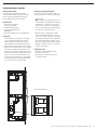
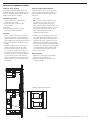
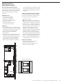
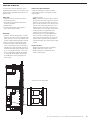
LCi-RTS105 LOUDSPEAKER
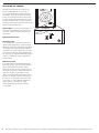
INSTALLATION
You will need:
• Pencil for marking the location
of installation.
• Keyhole saw, utility knife or material-
appropriate incising implement for
cutting drywall or other wall material.
• Level.
• Screwdriver, preferably powered,
with Phillips head bit.
• Power drill with appropriate bit
(optional, for starting wall cut).
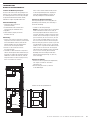
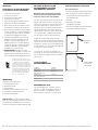
Trace around
the template.
Cut the hole with
the appropriate tool.
2 Polk Audio Customer Ser
vice: 1-800-377-7655 (Outside US & Canada: 410-358-3600)
Monday-Friday
, 9:00 AM-6:00 PM EST
,

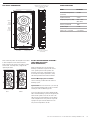
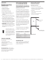
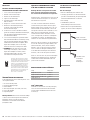
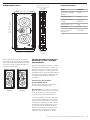
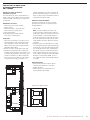
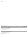
PHYSICAL DIMENSIONS
Note: LCi-RTS105 speakers are designed to be installed
as mirror imaged. This means that the tweeter is
always located on the outside as the speaker is mount-
ed into a wall. To accomplish this, simply turn the
speaker upside down.
LEFT RIGHT
STUD-LOCK MOUNTING SYSTEM™
(INCLUDED BUT ALSO
SOLD SEPARATELY)
While not absolutely necessary, the Stud-Lock
Mounting System™ does help ensure that LC
i-RTS
Series speakers perform at their optimum. The
mounting system creates a rigid platform for the
LC
i-RTS105, increasing bass performance, clarity
and reducing unwanted structure borne vibration.
Stud-Lock Mounting System
™
Installation
See the instructions included with each Stud-Lock
Mounting System
™
.
Important Note: For new construction: If you are using
a pr
e-construction bracket, always install it first before
installing the Stud-Lock Mounting System
™
.
If you are installing a pr
e-constr
uction bracket (PB105)
and a Stud-Lock Mounting System (STL105) together, be
aware that the speaker’s enclosure can catch on the
edge of the pr
e-construction bracket. Push the bottom
of the loudspeaker enclosure up and over The protrud-
ing edge of the pre-construction bracket. This will
fully seat The loudspeaker in the wall.
SPECIFICATIONS
M
odel LC
i-
RTS105
Recommended Amplification 10-250W
(
W/channel)
Impedance(Nominal) 4 Ohms
Frequency Response (+/-3dB) 50Hz – 27kHz
(80Hz-26kHz)
E
fficiency (2.83V@1M) 92db
Speaker Weight 12.5 lbs.
D
epth assum. 1/2" drywall 3 3/4" (9.5cm)
Cutout Width
10 5/8" (27.0cm)
For mor
e infor
mation visit our website at www
.polkaudio.com
3
C
utout
Height
20 1/8"
(
51.1cm)
M
ounting Depth
(Depth assum. 1/2" drywall)
3 3/4" (9.5cm)
O
verall
H
eight
21 7/8"
(55.4cm)
Overall Width
12" (30.5cm)
Depth measured from the back of the
e
nclosure to the back of the baffle
4
1/4" (10.8cm)

4 Polk Audio Customer Ser
vice: 1-800-377-7655 (Outside US & Canada: 410-358-3600)
Monday-Friday
, 9:00 AM-6:00 PM EST, [email protected]
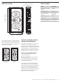
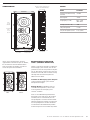
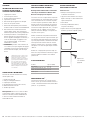
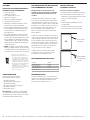
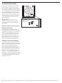
ADJUSTING THE TWEETER
Aiming the tweeter toward your listening position
improves imaging and detail. If you are using LC
i
Series In-wall Loudspeakers as front/main home the-
ater speakers, aim the tweeter toward your listening
position. For rear/surround speakers installed in walls
or ceilings, aim the tweeter toward the nearest reflect-
i
ng surface (an adjacent wall or ceiling) if you desire a
more diffuse sound field. For more direct sound, aim the
tweeters at your listening position).
Important Note: LCi Series In-wall Loudspeakers are
not magnetically shielded and should not be placed
closer than 1’ (30cm) from a direct-view television or
video monitor.
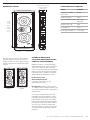
Room Environment Controls
3dB Tweeter Toggle
If your listening room is very reflective, with smooth
sheetrock walls, hardwood floors, and non-cushioned
furniture, the sound will be overly “bright” and unnatu-
ral. Engaging the LC
i tweeter attenuation feature (by
selecting the “cut” setting) compensates for the effect
of reflectivity in a hard room. Tweeter attenuation flat-
tens room response, without hindering higher frequency
response, for warmer, more realistic sound and more
accurate imaging.
Wall Distance Toggle
In-wall loudspeakers excel when placed more than 2’
(60cm) from side walls. If position limitations demand
that your loudspeakers be installed closer than 2’
(60cm) from side walls, the close proximity of the sur-
face can result in a response “bump” between 50 and
200Hz. This can cause in-wall speakers to sound
“boomy.” The distance toggle switch flattens response
and tunes out “boominess” without sacrificing deep
bass response, for more lifelike sound. If the speaker
is closer than 2’ to a wall, engage the wall distance
toggle (“Wall Dist.”) to match the <2’ setting.
Recommended speaker distance from side walls
is 2 feet (60cm).

For mor
e infor
mation visit our website at www
.polkaudio.com
5
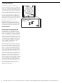
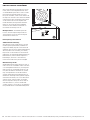
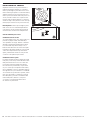
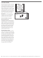
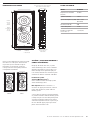
PAINTING IN-WALL GRILLES
Painting in-wall grilles
The LCi-RTS105 is supplied with two grilles,
one perforated aluminum, the other cloth-covered
plastic. The perforated aluminum grille may be
painted, while you may dye the cloth grille.
Required tools:
1. Paint of your choice (grilles
must be spray painted).
2. A paperclip or corkscrew (for
removing the paintable grille).
3. Masking tape
4. Paint mask (supplied; covers un-paintable parts)
Preparation:
1. Separate the parts of the speaker. If the speaker
is not yet installed, the grille can be removed
simply by pushing the clamp screws forward
to push the grille off the speaker from the inside.
2. Remove the cloth scrim from the inside of the grill.
3.
When painting the speaker frame, use the supplied
paint masks to carefully mask off the front of the
speakers to protect the drivers and baffles. You can
do this while the speaker is already installed in the
wall (if, for instance, you’re repainting the room).
If you do not have the paint masks, carefully mask
the speaker components using paper and masking
tape. Use a paper clip to remove the grille.
Painting the aluminum mesh grille:
The grille of the LCi Series speaker features an
even, protective paint. This paint is an ideal primer.
1. Paint the grille.
N
ote:
G
rilles must be spray painted. Do not use
a brush and paint. Thick, brushed paint may clog
the grille holes. Use thin coats of spray paint.
If you’re using a compressor and spray gun, use
the finest, most diffused setting. Be careful not
to fill the holes in the grille with paint.
2. When the paint is completely dry, carefully
reinstall the grille by fitting it into its recess so
that it is just resting on the frame. Starting with
one corner, go around the speaker and push the
grille into the grille notch a little bit at a time.
Be gentle; the grille may be easily bent by rough
handling. You will feel a positive “snap” when
the grille is fully in place.
Painting the frame:
1. Apply paint to exposed (unmasked) parts.
Use two or more thin coats.
2. When the paint is completely dry, remove
the masking material.
Hook up the speaker wir
es.

6 Polk Audio Customer Ser
vice: 1-800-377-7655 (Outside US & Canada: 410-358-3600)
Monday-Friday
, 9:00 AM-6:00 PM EST, [email protected]
PORTUGUÊS
I
MPORTANTES INSTRUCCIONES DE
SEGURIDAD LEER ANTES DE HACER
FUNCIONAR EL EQUIPO
1
. Lea estas instrucciones.
2. Guarde estas instrucciones.
3. Respete todas las advertencias.
4. Siga todas las instrucciones.
5. No use este aparato cerca del agua.
6
. Límpielo solamente con un paño seco.
7. No bloquee las aberturas de ventilación. Instale
el aparato de acuerdo con las instrucciones
del fabricante.
8. No lo instale cerca de fuentes de calor, tales como
radiadores, rejillas de piso, cocinas u otros aparatos
(incluso amplificadores) que producen calor.
9. Encargue todo servicio del aparato al personal de
servicio calificado. Se requiere servicio cuando el
aparato ha sido dañado de alguna manera han caído
líquidos u objetos dentro del aparato o el aparato se
ha dejado caer, ha dejado de funcionar normalmente
o ha sido expuesto a la lluvia o a la humedad.
10.
ADVERTENCIA. Para reducir el riesgo de incendio
o de descarga eléctrica, este aparato no debe ser
expuesto a la lluvia o a la humedad, y no se le deben
colocar encima objetos llenos de líquido, tales
como floreros.
Descarte do produto – Algumas leis ou regula-
mentos internacionais, nacionais e/ou locais
podem reger os procedimentos para descarte deste
produto. Para obter informações mais detalhadas,
entre em contato com a loja onde adquiriu o
produto ou com o importador ou distribuidor da
Polk Audio em seu país. Para obter uma lista dos
importadores/distribuidores da Polk Audio, visite
nosso website em www.polkaudio.com ou entre
em contato com a Polk Audio pelo endereço 5601
Metro Drive, Baltimore, Maryland 21215, USA—
Telefone: +1 410 358-3600.
VERIFIQUE O CONTEÚDO
Cada embalagem da caixa acústica modelo
LC
i-RTS105 contém:
1. Uma caixa acústica LC
i-RTS105
2. Modelo para instalação da caixa acústica
3. Proteção para pintura
4. Duas grades (uma de metal, uma de tecido)
5. Manual da LC
i-RTS105
6. Cartão de registro
Obser
vação impor
tante:
Se algum componente
estiver danificado ou faltando, ou se a caixa acústica
LC
i-RTS105 não funcionar, avise imediatamente os
Serviços de Suporte ao Instalador da Polk Audio
pelo númer
o 1-800-377-7655.
INSTALAÇÃO RECOMENDADA
PARA DESEMPENHO MÁXIMO
O
bservação importante: As caixas acústicas da
s
érie LCi-RTS destinam-se exclusivamente para
instalação em ambientes fechados e não foram
projetadas para uso ao ar livre.
O
instalador deve conhecer e observar plenamente
todos os códigos locais de edificações e prevenção
de incêndios. Deve também estar familiarizado com a
área situada atrás da parede ou teto no qual planeja
instalar as caixas acústicas. Use sempre fiação que
e
steja em conformidade com os códigos de edificações
e prevenção de incêndios relevantes. Use cabos de, no
mínimo, bitola 14 ou mais elevada para obter a melhor
qualidade de som possível. (Obs.: Para obter melhores
resultados, sugerimos que o cabeamento seja feito
por um profissional experiente).
Ao instalar as caixas acústicas da série LCi para
parede, considere o peso do modelo específico (veja
o peso do modelo em questão na página das especifi-
cações) e a firmeza do material no qual serão instal-
adas. Informe-se se existem e onde estão localizadas
vigas, fiação elétrica ou encanamentos ocultos
na parede ou teto onde as caixas acústicas
serão instaladas.
Caso não esteja seguro de possuir as habilidades ou
as ferramentas necessárias, consulte o revendedor
da Polk Audio ou um instalador profissional.
RECOMENDAÇÕES DE CABEAMENTO
Comprimentos Bitola
Até 7,6 m 18 ou 16
Entre 7,6 m e 15,2 m 16 ou 14
Entre 15,2 m e 22,9 m 14 ou 12
Mais de 22,9 m 12
DESEMPENHO THX
™
Para obter desempenho THX
™
, use a grade de tecido;
coloque a chave do tweeter na posição “nor
mal” e
a chave de compensação de distância da par
ede na
posição acima de 60 cm (>2).
INSTALAÇÃO DA CAIXA
ACÚSTICA LC
i-RTS105
Ferramentas necessárias:
• Lápis para marcar o local da instalação.
• Serra tico-tico, estilete ou implemento incisivo
apropriado para cortar gesso acartonado (drywall)
ou outro tipo de material de parede.
• Nível (prumo).
• Chave de fenda, de preferência elétrica,
com ponta Phillips.
•
Furadeira com broca apropriada (opcional,
para iniciar o corte na parede).
Traceje ao redor
do modelo.
Corte o orifício com a
ferramenta apropriada.

For mor
e infor
mation visit our website at www
.polkaudio.com
7
D
IMENSÕES FÍSICAS
Obs.: As caixas acústicas LCi-RTS105 são projetadas
para instalação tipo espelho. Isto significa que o tweet-
er fica sempre situado na parte externa quando a caixa
acústica é montada na parede. Para isto, basta virar a
caixa acústica de ponta-cabeça.
ESQUERDA DIREITA
STUD-LOCK MOUNTING SYSTEM™
(VENDIDO SEPARADAMENTE)
Apesar de não ser absolutamente necessário, o Stud-
Lock Mounting System™ ajuda a assegurar que o
desempenho das caixas acústicas da série LC
i-RTS seja
o melhor possível. Este sistema de instalação cria uma
plataforma rígida para a LC
i-RTS105, melhorando a
reprodução de graves e a clareza do som, e reduzindo
as vibrações indesejáveis produzidas pela estrutura.
Instalação do Stud-Lock Mounting System
™
Consulte as instruções fornecidas com cada
Stud-Lock Mounting System
™
.
Observação importante: No caso de construções
novas: Quando usar um suporte para montagem
pré-construção, sempre instale-o antes de instalar
o Stud-Lock Mounting System
™
.
Se for instalar um suporte para montagem pré-con-
strução (PB105), junto com um Stud-Lock Mounting
System (STL105), infor
mamos que o gabinete da caixa
acústica pode se enroscar na borda do suporte pré-
construção. Pressione o botão do gabinete da caixa
acústica para cima e sobre a borda saliente do suporte
pré-construção. Este procedimento encaixará com-
pletamente a caixa acústica na par
ede.
E
SPECIFICAÇÕES
Modelo LCi-RTS105
Amplificação recomendada 10-250W
(W/chanal)
Impedância (nominal) 4 Ohms
Resposta de freqüência 50Hz – 27kHz
(+/- 3 dB) (80Hz-26kHz)
Eficiência ( 2,83 V a 1 M) 92db
Peso da unidade 12,5 lbs. (5,7 kg)
P
rof. que supõe um drywall 1/2" 3 3/4" (9,5cm)
Larg
ura do recorte
10 5/8" (27,0cm)
R
ecorte
A
ltura
2
0 1/8"
(51,1cm)
Pro
f. que supõe um drywall 1/2"
3 3/4" (9,5cm)
Altura
T
otal
2
1 7/8"
(55,4cm)
Largura Total
12" (30,5cm)
P
rofundidade medida a partir da parte
t
raseira do gabinete, até o sonoflector
4 1/4" (10,8cm)

8 Polk Audio Customer Service: 1-800-377-7655 (Outside US & Canada: 410-358-3600) Monday-Friday, 9:00 AM-6:00 PM EST, [email protected]
AJUSTE DO TWEETER
Para melhorar a reprodução e os detalhes do som,
d
irecione o tweeter para a posição a ser ocupada pelo
ouvinte. Se as caixas acústicas de parede da série LC
i
forem usadas como unidades frontais/principais de um
sistema de cinema em casa, direcione o tweeter para a
posição preferida de audição. No caso de caixas acústi-
cas traseiras/surround instaladas em paredes ou tetos,
posicione os tweeters voltados para a superfície refle-
tora mais próxima (uma parede ou teto adjacente) se
desejar um campo de som mais difuso. Para obter uma
r
eprodução de som mais direta, direcione os tweeters
para a posição a ser ocupada pelo ouvinte).
Observação importante: As caixas acústicas de
parede da série LC
i não têm blindagem magnética e
não devem ser colocadas a menos de 30 cm de distân-
cia de aparelhos de televisão ou monitores de vídeo.
Controles ambientais
Chave de compensação do tweeter de 3 dB
Se o ambiente onde o som será reproduzido tiver
muita reflexão, divisórias ou paredes lisas de Sheet-
rock (gesso ou material acartonado), piso de madeira e
móveis sem estofamento, o som será excessivamente
”vívido” e sem naturalidade. A ativação do recurso de
atenuação do tweeter LCi (selecionando o ajuste ”cut”),
compensa o efeito da reflexividade em ambientes com
estas características. A atenuação do tweeter neutral-
iza a resposta acústica do ambiente, sem prejudicar
as altas freqüências, resultando em sons mais
realísticos e reprodução mais precisa.
Chave de compensação de distância da parede
Caixas acústicas de parede são excepcionais quando
posicionadas a mais de 60 cm de distância das paredes
laterais. Se as opções de posicionamento forem limi-
tadas e as caixas acústicas precisarem ser instaladas
a menos de 60 cm de distância das paredes laterais, a
proximidade da superfície pode resultar em um ”salto”
na resposta entre 50 Hz e 200 Hz. Isto pode fazer com
que o som das caixas acústicas de parede apr
esente
r
everberação. A chave de compensação de distância
neutraliza a r
esposta e elimina a r
everberação, sem
sacrificar a reprodução de graves profundos, resultando
em sons mais naturais. Se a caixa acústica estiver a
menos de 60 cm de distância de uma parede, ative a
chave de compensação de distância da par
ede (”Wall
Dist.”) para que coincida com o ajuste <2'. Recomen-
damos que a caixa acústica fique a 60 cm de
distância das par
edes laterais.

For mor
e infor
mation visit our website at www
.polkaudio.com
9
PINTURA DAS GRADES DE PAREDE
Pintura das grades de parede
A
LC
i-
RTS105 é fornecida com duas grades: uma
de alumínio perfurado e a outra de plástico revestido
com tecido. A grade de alumínio perfurado pode ser
pintada e a de tecido pode ser tingida.
Ferramentas necessárias:
1. Tinta de sua preferência (as grades devem
ser pintadas com tinta spray).
2. Um clipe para papel ou saca-rolhas (para
r
emover a grade).
3. Fita crepe
4. Proteção para pintura (fornecida; cobre as
partes que não podem ser pintadas).
Preparation:
1. Separe os componentes da caixa acústica. Se a
caixa acústica ainda não estiver instalada, basta
empurrar os parafusos de fixação para frente para
retirar a grade da caixa acústica de dentro para fora.
2. Retire o revestimento de tecido da parte interna
da grade.
3. Ao pintar a moldura da caixa acústica, use as
proteções para pintura fornecidas para cobrir
a frente da unidade e proteger os alto-falantes
e os sonoflectores. Isto pode ser feito depois de
a caixa acústica ter sido instalada na parede (se,
por exemplo, as paredes precisarem ser pintadas).
Se não tiver proteções para pintura, cubra com
cuidado os componentes da caixa acústica usando
papel e fita crepe. Use um clipe para papel para
retirar a grade.
Pintura da grade de alumínio perfurada:
A
grade da caixa acústica da série LCi é pintada de
maneira homogênea com uma tinta protetora. Esta
tinta constitui uma base ideal para aplicação de
outras tintas.
1. Pinte a grade.
Obs.: As grades devem ser pintadas com tinta
spray. Não use pincel e tinta. Tintas espessas
aplicadas com pincel podem entupir as per-
f
urações da grade. Aplique camadas finas de tinta
spray. Para pintar usando um compressor e pistola
de pintura, use o ajuste para spray mais fino e
difuso. Tome cuidado para não encher as
perfurações da grade com tinta.
2. Quando a tinta estiver totalmente seca, reinstale
com cuidado a grade encaixando-a na reentrância
até que fique apenas apoiada na moldura. Come-
çando em um dos cantos, empurre pouco a pouco
a grade contra a chanfradura de encaixe da grade,
até percorrer todo o perímetro da moldura. Proceda
com cuidado, pois a grade pode entortar facilmente
se for manuseada com rispidez. Quando a grade
estiver completamente encaixada, você sentirá
uma "pressão" positiva.
Pintura da moldura:
1. Aplique tinta às partes expostas (descobertas).
Aplique duas ou mais mãos de tinta.
2. Quando a tinta estiver totalmente seca, retire
o material de proteção.
Conexão dos cabos das caixas acústicas.

10 Polk Audio Customer Ser
vice: 1-800-377-7655 (Outside US & Canada: 410-358-3600)
Monday-Friday
, 9:00 AM-6:00 PM EST, [email protected]
DEUTSCH
W
ICHTIGE SICHERHEITSHINWEISE
V
OR BEDIENUNG DER GERÄTE DURCHLESEN
1. Lesen Sie diese Anweisungen durch
2. Behalten Sie diese Anweisungen.
3. Beachten Sie alle Warnhinweise.
4. Folgen Sie allen Anleitungen.
5
. Verwenden Sie diese Geräte nicht in der
Nähe von Wasser.
6. Reinigen Sie sie nur mit einem trockenen Tuch.
7
. Blockieren Sie keine Lüftungsöffnungen.
Installieren Sie die Geräte entsprechend
den Herstelleranweisungen.
8. Installieren Sie sie nicht in der Nähe von Wärme-
quellen wie Heizkörpern, Warmlufteintrittsöffnungen,
Öfen oder anderen wärmeerzeugenden Geräten
(einschließlich Verstärkern).
9. Lassen Sie alle Wartungen von geschulten Kunden-
diensttechnikern durchführen. Eine Wartung ist nötig,
wenn das Gerät auf irgendeine Weise beschädigt
wurde durch das Hineinfallen von Objekten, durch
Regen oder Feuchtigkeit, wenn es nicht richtig
funktioniert oder wenn es fallengelassen wurde.
10.
WARNUNG: Um die Gefahr eines Feuers oder
Stromschlags zu verringern, ist dieses Gerät vor
Regen oder Feuchtigkeit zu schützen, und mit
Flüssigkeit gefüllte Gefäße, wie Vasen, sollten
nicht auf diesem Gerät platziert werden.
Entsorgung – Die Entsorgung dieses Produkts
kann bestimmten internation-alen, nationalen
und/oder örtlichen Gesetzen und/oder Vorschriften
unterliegen. Detaillierte Informationen hierzu
erhalten Sie von dem Fachhändler, bei dem Sie
dieses Produkt gekauft haben, oder vom Polk
Audio-Importeur/Vertrieb in Ihrem Land. Eine
Liste von Importeuren/ Vertriebsfirmen für Polk
Audio erhalten Sie auf der Polk Audio-Website
www.polkaudio.com oder von Polk Audio, 5601
Metro Drive, Baltimore, Maryland 21215,
USA – Telefon: +1 410 358-3600.
ÜBERPRÜFUNG DES INHALTS
In der Verpackung jedes LCi-RTS105-Lautsprechers sollte
sich Folgendes befinden:
1. Ein LC
i-RTS105-Lautsprecher
2. Lautsprecher-Montagevorlage
3. Lackierschablone
4. Zwei Lautsprechergrills (einer Gitter, einer Stoff)
5. LC
i-R
TS105-Handbuch
6. Registrier
ungskar
te
Wichtiger Hinweis: Wenn etwas fehlt oder beschädigt
ist oder Ihr LC
i-RTS105-Lautsprecher nicht funktioniert,
kontaktier
en Sie bitte sofor
t den Installations-
Kundendienst von Polk Audio unter der Nummer
(USA) 800-377-7655.
INSTALLATIONSEMPFEHLUNGEN
FÜR DIE OPTIMALE LEISTUNG
W
ichtiger Hinweis: Lautsprecher der LC
i-
RTS-
S
erie sind nur für den Inneneinsatz konzipiert.
Sie sind nicht für den Außeneinsatz vorgesehen.
Wichtiger Hinweis: Lautsprecher der LCi-RTS-Serie sind
n
ur für den Inneneinsatz konzipiert. Sie sind nicht für
den Außeneinsatz vorgesehen.
Sie sollten sich mit den örtlichen Bau- und Feuer-
s
chutzvorschriften gut auskennen und diese genau
b
efolgen. Zudem sollten Sie genau wissen, was sich
hinter der Wand oder Decke befindet, in die Sie die
Lautsprecher installieren wollen. Verwenden Sie stets
Kabel, die die entsprechenden Bau- oder Feuer-
schutzvorschriften erfüllen. Verwenden Sie mind-
estens 14-Gauge-Draht, um die beste Soundqualität
zu gewährleisten. (Hinweis: Die V
erdrahtung sollte
am besten von einem Fachmann ausgeführt werden.)
Beachten Sie bei der Installation von Lautsprechern der
LC
i-Serie das Gewicht des jeweiligen Modells (siehe
hierzu den Abschnitt „Daten“) und die Stärke des
Materials, in das Sie den Lautsprecher installieren.
Passen Sie auch auf verborgene Stützbalken, elek-
trische Kabel oder Rohrleitungen in der Wand bzw.
Decke auf, in der Sie die Lautsprecher installieren.
Wenn Sie sich nicht sicher sind, ob Sie die benötigten
Fähigkeiten oder Werkzeuge besitzen, kontaktieren
Sie bitte Ihren Polk Audio-Fachhändler oder einen
professionellen Installateur.
EMPFOHLENE DRAHTSTÄRKEN
Länge Gauge-Wert
Längen bis zu 7,5 m 18 oder 16
Längen zwischen 7,5 und 15 m
16 oder 14
Längen zwischen 15 und 23 m 14 oder 12
Längen über 23 m 12
THX
™
-LEISTUNG
V
erwenden Sie für THX
™
den Stof
f-Lautsprechergrill,
stellen Sie den Hochtönerschalter auf die Normal-
position und den Wandabstandsschalter auf mehr
als 60 cm (>2).
LCi-RTS105-LAUTSPRECHER-
INSTALLATION
Was Sie benötigen:
• Bleistift zur Markierung der Installationsstelle.
• Stichsäge, Gipskartonmesser oder für das Material
p
assendes Schneidewerkzeug, um Gipskartonplatten
oder andere Wandmaterialien zu schneiden.
• Wasserwaage.
• Schraubendreher, am besten
E
lektrowerkzeug mit Kreuzschlitz-Einsatz.
•
Bohrmaschine mit entsprechendem Bohrer
(optional, um Schnitt in Wand zu beginnen).
Folgen Sie mit dem
Bleistift der Schablone.
Schneiden Sie das
Loch mit dem
passenden
Werkzeug aus.

For mor
e infor
mation visit our website at www
.polkaudio.com
11
ABMESSUNGEN
Hinweis: LCi-RTS105-Lautsprecher sind für die
spiegelverkehrte Installation konzipiert. Das bedeutet,
dass der Hochtöner sich bei der Wandinstallation
immer an der Außenseite befindet. Hierzu müssen
Sie den Lautsprecher einfach umdrehen.
LINKS RECHTS
BEFESTIGUNGSSYSTEM STUD-
LOCK™ (SEPARAT ERHÄLTLICH)
Obwohl es nicht absolut notwendig ist, gewährleistet
das Befestigungssystem Stud-Lock
™
, dass die Lauts-
precher der LC
i-RTS-Serie ihre optimale Leistung brin-
gen. Das Befestigungssystem bietet eine starre Platt-
form für den LC
i-RTS105, verbessert die Bassleistung
und Klangschärfe und reduziert ungewünschte
Vibrationen in der Struktur.
Installation des Befestigungssystems Stud-Lock
™
Siehe die jedem Befestigungssystem Stud-Lock
™
beiliegenden Anweisungen.
W
ichtiger Hinweis:
Für Neubauten: W
enn Sie
ine Rohbau-Halterung benutzen, ist diese immer
vor der Installation des Befestigungssystems
Stud-Lock
™
einzubauen.
W
enn Sie eine Rohbauhalter
ung (PB105) und das
Befestigungssystem Stud-Lock (STL105) zusammen
verwenden, müssen Sie daran denken, dass das
Lautsprechergehäuse sich an der Kante der Rohbau-
halter
ung ver
fangen kann. Drücken Sie die Unterseite
des Lautsprechergehäuses nach oben und über die
vorstehende Kante der Rohbauhalterung. Dadurch
wir
d der Lautspr
echer voll in die Wand eingeschoben.
DATEN
Modell LCi-RTS105
Empfohlene Verstärkerleistung 10-250W
(W/Kanal)
Nennimpedanz 4 Ohms
F
requenzgang (+/-3 dB) 50Hz – 27kHz
(80Hz-26kHz)
Leistung (2,83 V bei 1 M) 92db
Lautsprechergewicht 12.5 lbs.
Tiefe, die ein drywall 1/2"anni. 3 3/4" (9,5cm)
Ausschnitt-Bre
ite
10 5/8" (27,0cm)
A
usschnitt-
H
öhe
20 1/8"
(51,1cm)
T
iefe, die ein drywall 1/2"anni.
3 3/4" (9,5cm)
Höhe
2
1 7/8"
(
55,4cm)
B
reite
12" (30,5cm)
D
ie Tiefe vom Ende des Gehäuses zur
Rückseite der Schallwand beträgt
4
1/4" (10,8cm)

12 Polk Audio Customer Ser
vice: 1-800-377-7655 (Outside US & Canada: 410-358-3600)
Monday-Friday
, 9:00 AM-6:00 PM EST, [email protected]
EINSTELLUNG DES HOCHTÖNERS
W
enn Sie den Hochtöner auf Ihre Hörposition hin aus-
richten, verbessert dies Klangbild und Detail. Wenn
Sie Wandeinbaulautsprecher der LC
i-Serie als vordere
Lautsprecher oder Hauptlautsprecher eines Heim-
kinosystems verwenden, sollten Sie den Hochtöner auf
Ihre Hörposition ausrichten. Für in Decken oder Wänden
installierte hintere oder Surround-Lautsprecher richten
Sie den Hochtöner auf eine nahe liegende reflek-
tierende Oberfläche (eine angrenzende Wand oder
D
ecke) aus, um ein mehr gestreutes Klangbild zu
erreichen. Für einen direkteren Sound richten Sie
die Hochtöner auf Ihre Hörposition aus.
Wichtiger Hinweis: Die Wandlautsprecher der
LC
i-Serie sind nicht magnetisch abgeschirmt und
sollten mindestens 30 cm von einem Fernsehgerät
oder Videomonitor entfernt sein.
Raumumgebungs-Steuerelemente
3dB-Hochtönerabschwächung
Wenn der Raum, in dem Sie Musik hören, sehr stark
reflektiert (glatte Gipskartonwände, Holzböden und
ungepolsterte Möbel), klingt der Sound sehr hell und
unnatürlich. Wenn Sie die LCi-Hochtönerabschwächung
aktivieren (indem Sie die Einstellung „Cut“ wählen),
kompensieren Sie die Reflektionen in einem hart klin-
genden Raum. Die Hochtönerabschwächung glättet die
Raumreflektionen, ohne die höheren Frequenzen zu
beeinträchtigen, und erzielt so einen wärmeren,
realistischeren Sound und ein präziseres Klangbild.
Wandentfernungsschalter
Wandeinbaulautsprecher klingen am besten, wenn sie
mehr als 60 cm von Seitenwänden entfernt sind. Wenn
es aus Raumgründen erforderlich ist, die Lautsprecher
näher als 60 cm von Seitenwänden entfernt zu instal-
lieren, kann die Nähe der Seitenwand eine „Ausbeu-
lung“ im Frequenzbereich zwischen 50 und 200 Hz
erzeugen. Dadurch klingen die Wandlautsprecher oft
dröhnend. Der Entfernungsschalter glättet die Frequenz
und eliminier
t das Dröhnen, um so einen lebensechten
Sound zu erzielen, ohne den Tiefbass zu verringern.
Wen der Lautsprecher weniger als 60 cm (2 Fuß) von
einer Wand entfer
nt ist, stellen Sie den Abstand-
sschalter („Wall Dist.“) auf <2 Fuß ein. Der empfohlene
Lautsprecherabstand von Seitenwänden beträgt 60 cm.

For mor
e infor
mation visit our website at www
.polkaudio.com
13
LACKIEREN DER
WANDLAUTSPRECHERGRILLS
Lackieren der Wandlautsprechergrills
Der LCi-RTS105 wird mit zwei Lautsprechergrills aus-
geliefert, einem aus gelochtem Aluminium und einem
aus stoffbezogenem Kunststoff. Der Lautsprechergrill
aus gelochtem Aluminium kann lackiert werden,
während der Stoffgrill eingefärbt werden kann.
Erforderliche Werkzeuge:
1
. Gewünschte Farbe (Grills müssen
spritzlackiert werden).
2. Eine Büroklammer oder ein Korkenzieher
(zur Entfernung des lackierbaren Grills).
3. Kreppband
4. Lackierschablone (liegt bei, deckt nicht
lackierbare Teile ab).
Vorbereitung:
1. Trennen Sie die Teile des Lautsprechers: Wenn der
Lautsprecher noch nicht installiert ist, kann man den
Grill einfach dadurch entfernen, indem man die
Klammerschrauben nach vorne drückt und den
Grill von innen vom Lautsprecher drückt.
2. Entfernen Sie den Stoffeinsatz im Innern
des Lautsprechergrills.
3. Verwenden Sie beim Lackieren des Lautsprecher-
rahmens die beiliegende Lackierschablone dazu, an
der Vorderseite Treiber und Schallwand sorgfältig
abzudecken. Sie können dies auch tun, wenn der
Lautsprecher bereits installiert ist (beispielsweise,
wenn Sie ein Zimmer neu streichen).
Wenn Sie keine Lackierschablonen haben, können
Sie die Lautsprecherkomponenten sorgfältig mit
Papier und Kreppband abdecken. Entfernen Sie
den Lautsprechergrill mit einer Büroklammer.
Lackieren des Aluminium-Gittergrills:
Der Lautsprechergrill der LCi-Serie verfügt über eine
gleichmäßige Schutzlackierung. Diese Lackierung ist
e
ine ideale Grundierung.
1. Lackieren Sie den Lautsprechergrill.
Hinweis: Die Lautsprechergrills müssen spritzlackiert
werden. Verwenden Sie keinen Pinsel. Dicke, mit
Pinsel aufgetragene Farbe kann die Löcher des Grills
verstopfen. Verwenden Sie dünne, aufgespritzte Lacks-
chichten. Wenn Sieeinen Kompressor und eine Spritz-
pistole verwen den, müssen Sie die feinste, am weit-
esten zerstreute Einstellung wählen. Passen Sie auf,
dass Sie die Löcher im Grill nicht mit Lack verstopfen.
2. Wenn der Lack ganz getrocknet ist, bauen Sie den Grill
vorsichtig wieder ein, indem Sie ihn in seine Öffnung
einführen, so dass er gerade auf dem Rahmen aufsitzt.
Gehen Sie dann von einer Ecke aus um den ganzen
Lautsprecher herum und drücken Sie den Grill allmäh-
lich ein. Seien Sie vorsichtig, da der Grill durch
übermäßige Kraft leicht verbogen werden kann.
Wenn der Lautsprechergrill richtig sitzt, hören Sie,
wie er einschnappt.
Lackieren des Rahmens:
1. Lackieren Sie die frei liegenden (nicht abgedeckten)
Teile. Tragen Sie mindestens zwei dünne
Lackschichten auf.
2. Wenn der Lack ganz trocken ist, entfernen
Sie die Abdeckungen.
Schließen Sie die Lautsprecherdrähte an.

14 Polk Audio Customer Ser
vice: 1-800-377-7655 (Outside US & Canada: 410-358-3600)
Monday-Friday
, 9:00 AM-6:00 PM EST, [email protected]
ITALIANO
I
NFORMAZIONI IMPORTANTI PER LA
SICUREZZA LEGGERE PRIMA DI
UTILIZZARE L’EQUIPAGGIAMENTO
1. Leggere queste istruzioni.
2
. Conservare queste istruzioni.
3. Prestare attenzione alle avvertenze.
4. Seguire tutte le istruzioni
5. Non utilizzare questo apparato vicino all’acqua.
6. Pulire solo con un panno asciutto.
7. Non bloccare alcuna apertura per la ventilazione.
Installare secondo le istruzioni fornite dal fabbricante.
8. Non installare vicino a fonti di calore come ad
esempio radiatori, camini, stufe o altre apparec-
chiature che generino calore, inclusi gli amplificatori.
9. Contattare personale di assistenza qualificato per
qualsiasi intervento di assistenza. Ottenere assis-
tenza se l’apparato è danneggiato in alcun modo, se
è stato versato del liquido, se l’apparato è stato
esposto a pioggia o umidità, se non funziona
normalmente o se è caduto.
10.
AVVERTENZA: per evitare i rischi di incendio e di
scossa elettrica, non esporre l’apparato alla pioggia
o all’umidità e non posizionare sull’unità alcun con-
tenitore contenente un liquido, come ad esempio
un vaso.
Smaltimento del prodotto - Seguire le norme
internazionali, nazionali e locali per lo smal-
timento di questo prodotto. Per ulteriori
informazioni, contattare il proprio rivenditore
oppure l'importatore/distributore nel proprio
Paese. Per ottenere un elenco di import-
atori/distributori, visitare il sito Web Polk
Audio www.polkaudio.com oppure contat-
tare Polk Audio all'indirizzo 5601 Metro Drive,
Baltimore, Maryland 21215, USA -Telefono:
+1 410 358-3600.
COMPLETARE L’INVENTARIO
All’interno del contenitor
e del dif
fusore LC
i-RTS105,
troverete quanto segue:
1. Un diffusore LC
i-RTS105
2. Dima per il montaggio del dif
fusore
3. Copertura per verniciatura
4. Due mascherine (una in r
etino, una un tessuto)
5. Manuale dell’unità LC
i-RTS105
6. Scheda di registrazione
Nota importante: Nel caso in cui si notassero danni
o par
ti mancanti, oppur
e se il dif
fusore LC
i-R
TS105
non dovesse funzionare, notificare immediatamente
il servizio assistenza installazione Polk Audio al
numero 800-377-7655.
INSTALLAZIONE CONSIGLIATA
P
ER PRESTAZIONI OTTIMALI
Nota importante: I diffusori della serie LCi-RTS
sono solo per installazioni in ambienti chiusi.
Non sono concepiti per uso all’aperto.
È necessario conoscere e seguire tutte le norme locali
in materia edilizia e di sicurezza antincendio. È inoltre
necessario familiarizzarsi con l’area dietro la parete o
a
l soffitto nel quale si prevede di installare i diffusori.
U
tilizzare sempre cavi che permettano di rispettare le
norme edilizie e di sicurezza antincendio appropriate.
Per ottenere la migliore qualità del suono, si consiglia
di utilizzare cavi con 14 AWP di spessore minimo.
(Nota: per effettuare il cablaggio si consiglia di utiliz-
zare professionisti esperti.)
Durante l’installazione nella parete dei diffusori della
serie LC
i, prestare attenzione al peso del modello speci-
fico (vedere la pagina delle caratteristiche tecniche per
il peso del proprio modello) e alla robustezza del mate-
riale nel quale viene installato il diffusore. Prestare
attenzione a travetti nascosti, cavi elettrici e tubature
nella parete o nel soffitto nel quale vengono installati
i diffusori.
Qualora non si disponga dell’esperienza o degli stru-
menti necessari per effettuare l’installazione, rivolgersi
al proprio rivenditore Polk Audio o un installatore
professionista.
CAVI CONSIGLIATI
Distanza Spessore (AWP)
Fino a 7,5 m 18 o 16
Più di 7,5 m ma meno di 15 m 16 o 14
Più di 15 m ma meno di 22,5 m 14 o 12
Più di 22,5 m 12
PRESTAZIONI THX
™
Per ottenere le pr
estazioni THX
™
, utilizzare la masc-
herina in tessuto; posizionare l’interruttore tweeter su
“normal” e l’interruttore Wall Distance (distanza dalla
par
ete) su ">2" (più di 60 cm).
INSTALLAZIONE DEL
D
IFFUSORE LC
i-
RTS105
Sono necessari:
• Matita per contrassegnare la posizione in
cui effettuare l’installazione.
• Sega, lama o altro strumento necessario per
tagliare il cartongesso o altro materiale nella
superficie della parete.
• Livella a bolla.
• Cacciavite (preferibilmente elettrico)
con punta a stella Phillips.
• Trapano elettrico con la punta appropriata
(facoltativo, per iniziare a tagliare la parete).
Tracciare attorno
alla dima.
Tagliare il foro
con lo strumento
appropriato.

For mor
e infor
mation visit our website at www
.polkaudio.com
15
DIMENSIONI FISICHE
Nota: I diffusori LCi-RTS105 sono concepiti per un’in-
stallazione speculare. Ciò vuol dire che il tweeter è
sempre posizionato verso l’esterno quando il diffusore
è montato nella parete. Per far ciò basta capovolgere
il diffusore.
SINISTRA
DESTRA
SISTEMA DI MONTAGGIO
STUD-LOCK MOUNTING SYSTEM™
(VENDUTO SEPARATAMENTE)
Malgrado sia facoltativo, il sistema di montaggio
Stud-Lock Mounting System
™
favorisce l’ottenimento
delle prestazioni migliori dai diffusori della serie
LC
i-RTS. Il sistema di montaggio crea una piattaforma
rigida per il LC
i-RTS105 che permette di aumentare
le prestazioni dei bassi e la chiarezza e di ridurre le
vibrazioni indesiderate generate dalla struttura.
Installazione del sistema
Stud-Lock Mounting System
™
Consultare le istruzioni incluse con ogni
Stud-Lock Mounting System
™
.
Nota importante: Per edifici di nuova costruzione:
se si utilizzano staffe di montaggio prima della costru-
zione, installarle sempre prima del sistema Stud-Lock
Mounting System
™
.
Se si utilizzano contemporaneamente una staffa
di montaggio pre-costruzione (PB105) e il sistema
di montaggio Stud-Lock Mounting System (STL105),
prestare attenzione al fatto che la cassa potrebbe
r
estar
e bloccata sul bor
do della staf
fa di montaggio
pre-costruzione. Premere il lato inferiore della cassa
verso l’alto e al di sopra del lato sporgente della
staf
fa di montaggio pre-costruzione. In questo modo
è possibile posizionar
e completamente il dif
fusor
e
nella parete.
CARATTERISTICHE TECNICHE
Modello LCi-RTS105
A
mplificazione consigliata 10-250W
(W per canale)
Impedenza (nominale) 4 Ohms
Risposta in frequenza (+/-3 dB) 50Hz – 27kHz
(80Hz-26kHz)
Efficienza (2,83 V a 1 M) 92db
Peso del diffusore 12.5 lbs.
Prof. che amme.un drywall 1/2" 3 3/4" (9,5cm)
Larghezza dell’apertura
10 5/8" (27,0cm)
Altezza
dell’apertura
2
0 1/8"
(
51,1cm)
Prof. che amme.un drywall 1/2"
3 3//4" (9,5cm)
A
ltezza
generale
21 7/8"
(
55,4cm)
Larghezza generale
12" (30,5cm)
P
rofondità misurata dal retro della
c
assa al retro del baffle
4 1/4" (10,8cm)

16 Polk Audio Customer Ser
vice: 1-800-377-7655 (Outside US & Canada: 410-358-3600)
Monday-Friday
, 9:00 AM-6:00 PM EST, [email protected]
REGOLAZIONE DEL TWEETER
Angolando il tweeter verso la posizione d’ascolto si
migliorano riproduzione e dettaglio. Se si utilizzano i
d
iffusori per montaggio in parete della serie LC
i c
ome
diffusori anteriori/principali di un sistema home theatre,
angolare il tweeter verso la posizione d’ascolto. Per i
diffusori posteriori/surround installati nelle pareti o nel
s
offitto, orientare il tweeter verso la superficie riflet-
t
ente più vicina (una parete adiacente o il soffitto) per
ottenere un campo sonoro più diffuso. Per un suono più
diretto, dirigere i tweeter verso la posizione d’ascolto).
N
ota importante:
I
diffusori per montaggio in parete
d
ella serie LC
i n
on sono schermati magneticamente
e non devono essere posizionati a meno di 30 cm da
un monitor video o un televisore a immagine diretta.
Controlli ambientali per la stanza
Commutatore tweeter di 3 dB
Se la stanza riflette molto il suono, grazie a pareti lisce,
pavimento in par
quet e mobili senza imbottiture, il
suono potrebbe essere troppo ”brillante” e innaturale.
Attivando la funzionalità di attenuazione dei tweeter
LC
i (selezionando l’impostazione di taglio “cut”) si
bilancia l’effetto della riflessione in una stanza rigida.
L’attenuazione dei tweeter appiattisce la risposta della
stanza senza compromettere la risposta ad alte fre-
quenze, permettendo di ottenere un suono più caldo
e realistico e una riproduzione più accurata.
Commutatore distanza parete
Per ottenere la migliori prestazioni da diffusori montati
nelle pareti, è necessario posizionarli ad almeno 60 cm
dalle pareti laterali. Nel caso in cui fosse necessario
posizionarli a meno di 60 cm dalle pareti laterali a
causa di vincoli nel posizionamento, ciò può causare
un “picco” nella risposta in frequenza tra 50 e 200 Hz,
che fa “rimbombare” il suono. Il commutatore della dis-
tanza appiattisce la risposta e diminuisce il “rimbombo”
senza sacrificare la risposta dei bassi profondi, ottenen-
do un suono più naturale. Se il dif
fusore è a meno di
60 cm dalla parete, posizionare il commutatore della
distanza dalla parete (“Wall Dist.”) sull’opzione
<2’ (<60 cm). Si consiglia una distanza di 60 cm
tra i dif
fusori e le pareti laterali.

For mor
e infor
mation visit our website at www
.polkaudio.com
17
VERNICIATURA DELLE
MASCHERINE DA PARETE
V
erniciatura delle mascherine da parete
Il LCi-RTS105 viene fornito con due mascherine, una in
alluminio perforato e l’altra in plastica ricoperta di tes-
suto. La mascherina in alluminio perforato può essere
v
erniciata, mentre la mascherina in tessuto può
e
ssere tinta.
Strumenti necessari:
1. Vernice (utilizzare verniciatura
a
spruzzo per le mascherine).
2
. Una graffetta o un cavatappi (per
rimuovere la mascherina verniciabile).
3. Nastro adesivo protettivo
4. Copertura per verniciatura (inclusa,
copre le parti da non verniciare).
Preparazione:
1. Separare le parti del diffusore. Se il diffusore non è
ancora installato, rimuover
e la mascherina premendo
semplicemente le viti di contatto in avanti per sepa-
rare la mascherina dal diffusore dall’interno.
2. Rimuovere il filtro in tessuto dall’interno
della mascherina.
3. Quando si vernicia la cassa del diffusore, utilizzare
le coperture per verniciatura incluse per coprire la
parte anteriore dei diffusori per proteggere i driver
e i baffle. Ciò può essere fatto anche quando il
diffusore è montato nella parete (per esempio
quando si vernicia la stanza). Se le coperture non
f
ossero più disponibili,coprire attentamente i compo-
nenti del diffusore utilizzando carta e nastro adesivo
protettivo. Per rimuovere la mascherina, utilizzare
una graffetta.
V
erniciare la mascherina in retino di alluminio:
La mascherina del diffusore della serie LCi è coperto
con uno strato uniforme di vernice protettiva. Questo
strato di vernice è ideale come mano di fondo.
1
. Verniciare la mascherina.
Nota: Le mascherine devono essere verniciate a
spruzzo. Non utilizzare un pennello, poiché la vernice
potrebbe otturare i fori. Applicare uno strato sottile
di vernice a spruzzo. Se si utilizza un compressore e
una pistola a spruzzo, selezionare la modalità con il
flusso più fine e diffuso. Prestare attenzione a non
otturare i fori nella mascherina con la vernice.
2.
Quando la vernice è completamente asciutta,
reinstallare la mascherina inserendola nell’apposita
rientranza in modo che sia appoggiata alla cassa.
Partendo da un angolo, premere la mascherina un
poco alla volta lungo il perimetro facendola entrare
nella tacca apposita. Eseguire questa operazione con
cautela. Se si maneggia troppo duramente la mas-
cherina, la si può piegare. Quando la mascherina è
in completamente posizione, si nota uno “scatto.”
Verniciare la mascherina:
1. Applicare la vernice alle parti non coperte.
Usare due mani leggere di vernice.
2. Quando la vernice è completamente asciutta,
rimuovere il materiale di copertura.
Collegare i cavi del dif
fusor
e.

18 Polk Audio Customer Ser
vice: 1-800-377-7655 (Outside US & Canada: 410-358-3600)
Monday-Friday
, 9:00 AM-6:00 PM EST, [email protected]
ESPAÑOL
I
NSTRUÇÕES DE SEGURANÇA IMPORTANTES
LER ANTES DE USAR O EQUIPAMENTO
1. Leia estas instruções.
2. Guarde estas instruções.
3. Preste atenção a todos os avisos.
4
. Siga todas as instruções.
5. Não use este aparelho perto de água.
6. Limpe apenas com um pano seco.
7. Não bloqueie as aberturas de ventilação. Instale
de acordo com as instruções do fabricante.
8. Não instale próximo de quaisquer fontes de calor,
tais como radiadores, saídas de ar quente, fogões
ou outros aparelhos (incluindo amplificadores)
que produzam calor.
9. Toda a manutenção deve ser realizada por pessoal
de manutenção qualificado. É necessário prestar
assistência técnica ao aparelho quando tiver sofrido
danos de qualquer tipo, derramamento de líquido
ou queda de objetos sobre o aparelho, exposição do
aparelho à chuva ou umidade, mal funcionamento
ou queda do aparelho.
10.
AVISO: Para reduzir o risco de incêndio ou choque
elétrico, este aparelho não deve ser exposto à chuva
ou à umidade. Objetos que contenham líquidos, como
vasos, não devem ser colocados sobre este aparelho.
Descarte do produto – Algumas leis ou
regulamentos internacionais, nacionais e/ou
locais podem reger os procedimentos para
descarte deste produto. Para obter informações
mais detalhadas, entre em contato com a loja
onde adquiriu o produto ou com o importador
ou distribuidor da Polk Audio em seu país. Para
obter uma lista dos importadores/distribuidores
da Polk Audio, visite nosso website em
www.polkaudio.com ou entre em contato com
a Polk Audio pelo endereço 5601 Metro Drive,
Baltimore, Maryland 21215, USA—
Telefone: +1 410 358-3600.
HAGA INVENTARIO
Dentro de cada contenedor de altavoz
LC
i-RTS105 debe haber lo siguiente:
1. Un altavoz LC
i-RTS105
2. Una plantilla de montaje de altavoz
3. Una máscara para pintar
4. Dos rejillas (una de metal y una de tela)
5. Un manual LC
i-RTS105
6. Una tarjeta de registro
Nota impor
tante:
Si falta algo, si hay algo dañado
o si el altavoz LC
i-RTS105 no funciona, comuníquese
inmediatamente con el Servicio de apoyo al instalador
de Polk Audio llamando al 800-377-7655.
RECOMENDACIÓN DE INSTALACIÓN
PARA RENDIMIENTO ÓPTIMO
Nota importante. Los altavoces de la serie
LC
i-RTS son sólo para instalación en ambientes
interiores. No han sido diseñados para uso al
aire libre.
U
sted debe conocer bien y seguir todos los códigos
de construcción y de incendio locales. Además, debe
saber qué hay detrás de la pared o del cielo raso en el
cual planea instalar los altavoces. Utilice siempre cable
que cumpla con los códigos de construcción y de incen-
dio correspondientes. Utilice cable calibre 14 o más
grueso para obtener la mejor calidad de sonido.
(Nota. Es mejor que un profesional con experiencia
haga el cableado.)
Cuando instale altavoces empotrados en la pared de la
serie LC
i, tenga en cuenta el peso de su modelo en par-
ticular (vea la página de especificaciones para saber el
peso de su modelo) y la resistencia del material en el
cual va a instalar el altavoz. Tenga en cuenta los para-
les verticales, el cableado eléctrico y las tuberías que
pueda haber dentro de la pared o encima del cielo
raso en el cual va a instalar los altavoces.
Si duda de tener las herramientas o capacidades
necesarias para hacer esta instalación, consulte
a Polk Audio o a un instalador profesional.
RECOMENDACIONES DE CABLE
Trayectos Calibre
De hasta 25 pies 18 ó 16
Entre 25 y 50 pies 16 ó 14
Entre 50 y 75 pies 14 ó 12
Más de 75 pies 12
RENDIMIENTO THX
™
Para obtener rendimiento THX
™
, use la rejilla de tela;
ponga el selector basculante de tweeter en la posición
"Normal" y el selector basculante de distancia a la
pared en la posición "Más de 2 pies" (>2).
INSTALACIÓN DEL
ALTAVOZ LC
i-RTS105
Usted va a necesitar lo siguiente:
• Un lápiz para marcar la ubicación de la instalación.
• Una sierra caladora, un cuchillo utilitario o una
h
erramienta incisiva apropiada para cortar la pared
de yeso o el material de la pared.
• Un nivel
• Un destornillador, preferiblemente eléctrico,
c
on punta Phillips.
•
Un taladro eléctrico con la broca apropiada
(opcional, para iniciar el corte en la pared).
Trace el contorno
de la plantilla.
Haga una abertura
con la herramienta
apropiada.

For mor
e infor
mation visit our website at www
.polkaudio.com
19
DIMENSIONES FÍSICAS
Nota: Los altavoces LCi-RTS105 han sido diseñados
para instalarse como pares especulares. Esto significa
que el tweeter queda siempre del lado de afuera cuan-
do el altavoz se monta en la pared. Para lograr esto,
simplemente invierta el altavoz.
IZQUIERDA
DERECHA
SISTEMA DE MONTAJE STUD-LOCK
MOUNTING SYSTEM™ (SE VENDE
POR SEPARADO)
Aunque no es absolutamente necesario, el sistema de
montaje Stud-Lock Mounting System
™
contribuye a ase-
gurar que los altavoces de la serie LC
i-RTS se desem-
peñen de manera óptima. El sistema de montaje Stud-
Lock Mounting System
™
crea una plataforma rígida para
el LC
i-RTS105, lo cual aumenta el rendimiento de bajos
y la claridad y reduce la vibración producida por
la estructura.
Instalación del sistema de montaje
Stud-Lock Mounting System
™
V
ea las instr
ucciones que vienen con cada sistema
de montaje Stud-Lock Mounting System
™
.
Nota importante: En las estructuras en construcción
donde vaya a utilizar soportes previos a la construcción,
instale siempre tales sopor
tes antes de instalar el
sistema de montaje Stud-Lock Mounting System
™
.
Si usted está instalando un soporte de instalación pre-
via a la construcción (PB105) junto con un sistema de
montaje Stud-Lock Mounting System (STL105), tenga
en cuenta que la caja del altavoz se puede enganchar
en el borde del soporte de instalación previa a la con-
strucción. Levante la parte de abajo de la caja del
altavoz por encima del bor
de saliente del soporte de
instalación previa a la construcción. Esto hará que
el altavoz se asiente completamente en la pared.
ESPECIFICACIONES
M
odelo LC
i-
RTS105
Amplificación recomendada 10-250W
(W/canal)
Impedancia (nominal) 4 Ohms
R
espuesta de frecuencias 50Hz – 27kHz
(+/-3 dB) (80Hz-26kHz)
Eficiencia (2.83 V a 1 m) 92db
Peso del altavoz 12.5 lbs.
Prof. si se asume que 3 3/4" (9,5cm)
un drywall 1/2"
Ancho del corte
10 5/8" (27,0cm)
A
lto
d
el corte
20 1/8"
(51,1cm)
Prof. si se asume que
un drywall 1/2"
3 3/4" (9,5cm)
Alto
t
otal
2
1 7/8"
(
55,4cm)
Ancho total
12" (30,5cm)
P
rofundidad medida desde la parte
d
e atrás de la caja hasta la parte
d
e atrás del bafle
4 1/4" (10,8cm)

20 Polk Audio Customer Ser
vice: 1-800-377-7655 (Outside US & Canada: 410-358-3600)
Monday-Friday
, 9:00 AM-6:00 PM EST, [email protected]
AJUSTE DEL TWEETER
Apuntar el tweeter hacia la posición del oyente mejora
la formación de imágenes y el detalle. Si está utilizando
altavoces empotrados en la pared de la serie LC
i-RTS
c
omo altavoces de cine en casa frontales y principales,
apunte el tweeter hacia la posición del oyente. En el
caso de los altavoces de atrás o los altavoces surround
instalados en las paredes o en los cielos rasos, apunte
el tweeter hacia la superficie reflectora más cercana
(una pared adyacente o el cielo raso) si desea un campo
de sonido difuso. Para obtener sonido más directo,
apunte los tweeters hacia la posición del oyente.
N
ota importante:
L
os altavoces empotrados en
la pared de la serie LC
i no tienen blindaje magnético
y no deben colocarse a menos de 1 pie (30 cm)
de monitores y televisores de visión directa.
Controles del ambiente de la habitación
Selector de tweeter de 3 dB
Si la habitación es demasiado reflectora y tiene pare-
des de plancha de yeso lisas, suelos de madera dura
y muebles no acolchados, el sonido será excesivamente
”brillante” y artificial. Activar la característica de aten-
uación del tweeter LC
i (poniendo el selector en la posi-
ción de corte ”cut”) compensa los efectos de reflexión
de las habitaciones duras. La atenuación de tweeter
aplana la respuesta de la habitación sin afectar de
manera negativa la respuesta de altas frecuencias.
Esto produce un sonido más cálido y realista y una
formación de imágenes más precisa.
Selector de distancia a la pared
Los altavoces empotrados en la pared son excelentes
cuando se colocan a más de 2 pies (60 cm) de las pare-
des laterales. Si las limitaciones de posición exigen que
los altavoces sean instalados a menos de 2 pies (60 cm)
de las paredes laterales, la proximidad de las superfi-
cies puede producir un aumento de respuesta entre
50 y 200 Hz. Esto puede hacer que los altavoces empo-
trados en la pared retumben. El selector de distancia
aplana la respuesta y filtra el retumbo sin sacrificar la
r
espuesta de bajos pr
ofundos. Esto produce un sonido
más natural y r
ealista. Si el altavoz está a menos de
2 pies de la pared, ponga el selector de distancia a la
pared (”Wall Dist.”) en la posición para menos de
2 pies (<2'). La distancia recomendada del altavoz
a las paredes laterales es de 2 pies (60 cm).
Seite laden ...
Seite laden ...
Seite laden ...
Seite laden ...
Seite laden ...
Seite laden ...
Seite laden ...
Seite laden ...
-
 1
1
-
 2
2
-
 3
3
-
 4
4
-
 5
5
-
 6
6
-
 7
7
-
 8
8
-
 9
9
-
 10
10
-
 11
11
-
 12
12
-
 13
13
-
 14
14
-
 15
15
-
 16
16
-
 17
17
-
 18
18
-
 19
19
-
 20
20
-
 21
21
-
 22
22
-
 23
23
-
 24
24
-
 25
25
-
 26
26
-
 27
27
-
 28
28


Polk Audio LCi-RTS105 Benutzerhandbuch
- Kategorie
- Lautsprecher
- Typ
- Benutzerhandbuch
- Dieses Handbuch ist auch geeignet für
in anderen Sprachen
- English: Polk Audio LCi-RTS105 User manual
- français: Polk Audio LCi-RTS105 Manuel utilisateur
- español: Polk Audio LCi-RTS105 Manual de usuario
- italiano: Polk Audio LCi-RTS105 Manuale utente
- português: Polk Audio LCi-RTS105 Manual do usuário
Verwandte Papiere
-
Polk Audio LCi-RTS100 Benutzerhandbuch
-
-
-
-
Polk Audio 620-RT Bedienungsanleitung
-
-
Polk RTI A1 Benutzerhandbuch
-
Polk CSI A6 Benutzerhandbuch
-
Polk Audio CSI A6 Benutzerhandbuch
-
Polk Audio PA250.2 Benutzerhandbuch
