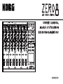
Korg ZERO 8 Bedienungsanleitung
- Kategorie
- Musikinstrumente
- Typ
- Bedienungsanleitung
Dieses Handbuch ist auch geeignet für

1

2
IMPORTANT SAFETY INSTRUCTIONS
• Read these instructions.
•Keep these instructions.
• Heed all warnings.
•Follow all instructions.
• Do not use this apparatus near water.
• Mains powered apparatus shall not be exposed to dripping or splashing and
that no objects filled with liquids, such as vases, shall be placed on the
apparatus.
• Clean only with dry cloth.
• Do not block any ventilation openings. Install in accordance with the
manufacturer's instructions.
• Do not install near any heat sources such as radiators, heat registers, stoves,
or other apparatus (including amplifiers) that produce heat.
• Do not defeat the safety purpose of the polarized or grounding-type plug. A
polarized plug has two blades with one wider than the other. A grounding type
plug has two blades and a third grounding prong. The wide blade or the third
prong are provided for your safety. If the provided plug does not fit into your
outlet, consult an electrician for replacement of the obsolete outlet. (for U.S.A.
and Canada)
• Protect the power cord from being walked on or pinched particularly at plugs,
convenience receptacles, and the point where they exit from the apparatus.
• Only use attachments/accessories specified by the manufacturer.
• Unplug this apparatus during lightning storms or when unused for long periods
of time.
•Turning off the power switch does not completely isolate this product from the
power line so remove the plug from the socket if not using it for extended
periods of time.
• Install this product near the wall socket and keep the power plug easily
accessible.
•WARNING—This apparatus shall be connected to a mains socket outlet with a
protective earthing connection.
• Refer all servicing to qualified service personnel. Servicing is required when
the apparatus has been damaged in any way, such as power-supply cord or
plug is damaged, liquid has been spilled or objects have fallen into the
apparatus, the apparatus has been exposed to rain or moisture, does not
operate normally, or has been dropped.
• Do not install this equipment on the far position from wall outlet and/or
convenience receptacle.
• Do not install this equipment in a confined space such as a box for the
conveyance or similar unit.
• Use only with the cart, stand, tripod, bracket, or table specified by the
manufacturer, or sold with the apparatus. When a cart is used, use caution
when moving the cart/apparatus combination to avoid injury from tip-over.
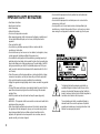
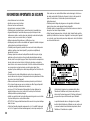
The lightning flash with arrowhead symbol within an
equilateral triangle, is intended to alert the user to the
presence of uninsulated “dangerous voltage” within the
product's enclosure that may be of sufficient magnitude to
constitute a risk of electric shock to persons.
The exclamation point within an equilateral triangle is
intended to alert the user to the presence of important
operating and maintenance (servicing) instructions in the
literature accompanying the product.

3
THE FCC REGULATION WARNING (for U.S.A.)
This equipment has been tested and found to comply with the limits for a Class B
digital device, pursuant to Part 15 of the FCC Rules. These limits are designed to
provide reasonable protection against harmful interference in a residential
installation. This equipment generates, uses, and can radiate radio frequency
energy and, if not installed and used in accordance with the instructions, may
cause harmful interference to radio communications. However, there is no
guarantee that interference will not occur in a particular installation. If this
equipment does cause harmful interference to radio or television reception, which
can be determined by turning the equipment off and on, the user is encouraged to
try to correct the interference by one or more of the following measures:
• Reorient or relocate the receiving antenna.
• Increase the separation between the equipment and receiver.
• Connect the equipment into an outlet on a circuit different from that to which the
receiver is connected.
• Consult the dealer or an experienced radio/TV technician for help.
Unauthorized changes or modification to this system can void the user’s authority
to operate this equipment.
• In North America use only on 120V supply.
* FireWire and FireWire symbol are trademarks of Apple Computer, inc., registered
in the U.S. and other countries. The FireWire logo is a trademark of Apple
Computer, Inc.
* Company names, product names, and names of formats etc. are the trademarks
or registered trademarks of their respective owners.
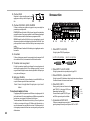
Notice regarding disposal
If this “crossed-out wheeled bin” symbol is shown on the product or
in the operating manual, you must dispose of the product in an
appropriate way. Do not dispose of this product along with your
household trash. By disposing of this product correctly, you can avoid
environmental harm or health risk. The correct method of disposal
will depend on your locality, so please contact the appropriate local
authorities for details.

4
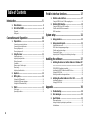
Table of Contents
Introduction.....................................................5
1. Main features ........................................................... 5
2. Parts of the ZERO8 ................................................... 6
Top panel .................................................................................................... 6
Rear panel................................................................................................... 8
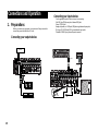
Connections and Operation ...........................10
1. Preparations........................................................... 10
Connecting your output devices .............................................................. 10
Connecting your input devices ................................................................ 10
Turning the power on ............................................................................... 11
Turning the power off ............................................................................... 11
2. Using the mixer ...................................................... 11
Selecting the inputs.................................................................................. 11
Adjusting the input levels........................................................................ 12
Mixing the sounds ................................................................................... 12
Crossfader................................................................................................. 12
Master output / Booth output ..................................................................12
Monitoring ............................................................................................... 12
Adjusting the effect levels ........................................................................ 13
3. Equalizer................................................................ 13
4. BPM system............................................................ 14
Setting the BPM manually ...................................................................... 14
Setting the BPM using tap tempo ........................................................... 14
Setting the BPM automatically ............................................................... 14
5. Effects .................................................................... 15
Effect types ............................................................................................... 15
Operating the effects ................................................................................ 16
FireWire interface functions ...........................17
1. FireWire audio interface ......................................... 17
Using the ZERO8 at the 192 kHz sampling rate .................................... 18
2. FireWire MIDI interface ........................................... 19
Using the ZERO8 as a MIDI controller.................................................. 19
FireWire Audio/MIDI device name list ................................................... 20
MIDI connections .................................................................................... 21
System setup.................................................22
1. Setup procedure ..................................................... 22
2. Setup parameter guide ........................................... 22
Selecting the fader curve .......................................................................... 22
MIDI control change message settings .................................................... 23
FireWire audio output settings ................................................................ 25
Viewing the EQ types .............................................................................. 25
Adjusting the LCD display, and initializing the settings ....................... 25
Installing the software ...................................27
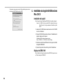
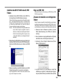
1. Installing the driver and editor software in Windows XP
.............................................................................. 27
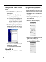
ZERO4/ZERO8 application installer...................................................... 27
Installing the KORG FireWire Audio/MIDI driver ................................ 28
Setting up ZERO Edit ............................................................................. 28
Allowing installation of unsigned drivers ............................................... 28
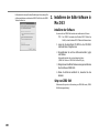
2. Installing the editor software in Mac OS X ............... 29
Installing the software.............................................................................. 29
Setting up ZERO Edit ............................................................................. 29
Appendix......................................................30
1. Troubleshooting ...................................................... 30
2. Error messages....................................................... 33
3. Specifications ......................................................... 33
Main specifications .................................................................................. 33
Analog and digital input/output specifications ....................................... 33
Included items .......................................................................................... 34

5
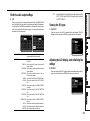
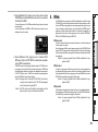
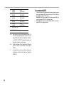
Auto BPM detection
An auto BPM detector is built-in, allowing you to detect the BPM of audio
material on a specific channel. You can use tap tempo alone or in conjunc-
tion with auto BPM to enhance the tempo detection. (Manual BPM can also
be used.) BPM Delays and other effects can be synchronized to the speci-
fied BPM.
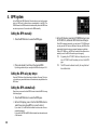
Push-knob MIDI controller
In addition to the knobs of the mixer channels, there are eight push-knobs
that you can use as MIDI controllers. You can assign switch operations and
encoder operations to each of the eight push-knobs, and create four banks
of these assignments, letting you control a total of 64 parameters
(“switch+encoder” x eight x four banks).
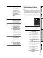
Touch-panel LCD
The ZERO8 features a TouchView LCD that functions as a display and also
offers intuitive, on-screen parameter editing. In addition, the LCD panel
borrows from KORG KAOSS technology, so you can also control multiple
effect or MIDI parameters in real time.
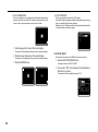
Mic preamps
The mic preamps built into the MIC jacks use high audio quality circuitry
designed with the cooperation of Peter Watts Designs Corporation.
This logo is the property of the Peter Watts Designs Corpo-
ration led by Peter Watts, a veteran designer of numerous
professional audio devices throughout his tenure at the
Trident Audio Corporation in the UK and as chief engineer
and developer at Mackie Designs in the USA.
Introduction
Thank you for purchasing the Korg LIVE CONTROL CONSOLE ZERO8.
To ensure full enjoyment of your new purchase, please read this owner’s
manual carefully and use the product as directed.
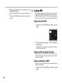
1. Main features
Eight-channel stereo digital mixer
The ZERO8 is a 24-bit stereo digital mixer that supports sampling frequen-
cies of 44.1 kHz, 48 kHz, 96kHz, and even 192 kHz for ultra-high quality
audio.
FireWire audio/MIDI interface
The ZERO8 is also an audio/MIDI interface via featuring two FireWire
connections. By connecting your computer and ZERO8 via a FireWire
cable, and you’ll be able to transfer audio and MIDI data to and from the
ZERO8. Up to 16 channels (in and out) of audio data transfer are sup-
ported.
Flexible channel selection
In addition to mic/guitar/line/phono analog audio inputs, the ZERO8
also provides digital audio inputs from the FireWire interface. In addition,
each mixer channel can also serve as a MIDI controller, giving you flexible
control of your audio sources.
EQ type selector
You can specify the type of EQ for each channel. The EQ types include typi-
cal EQ curves tuned to a particular musical genre, as well as types avail-
able only with digital processing, such as filters and isolators.
Fader/crossfader curve controller
Parameters are provided so that you can create your own fader curves and
crossfader curve. Since you can specify the fader curve separately for each
channel, you can obtain the exact sharpness and play you want for the fad-
ers. The crossfader lets you smoothly transition between audio sources.

6
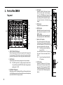
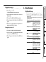
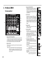
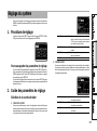
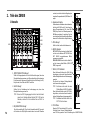
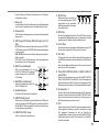
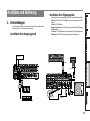
2. Parts of the ZERO8
Top panel
1–10
12, 13
11
28
14–16
17–20
21
27
22
23
24, 25
26
1. INPUT SELECTOR knob
Selects the input jack or FireWire audio signal that will be assigned to
the mixer channel. With this knob in certain positions, the send knobs,
pan knob, EQ knobs and/or faders will operate as MIDI controllers.
2. GAIN knob
Adjust the gain of the audio input assigned to the mixer channel.
TIP: If the MIC input level is too high, causing the sound to dis-
tort, press the rear panel MIC GAIN switch to change the mic
preamp gain to LOW.
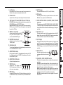
3. EQ SELECTOR knob
Selects the type of EQ. Switching the EQ type will change the function
of the EQ knobs or vary the tonal character that occurs when adjusting
each of the HI/MID/LO frequency bands.
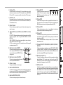
4. EQ knobs
Normally, the HIGH, MID, and LO knobs
boost or cut the sound in each frequency
range. The MID-FREQ knob changes the
center frequency of the MID range. Depend-
ing on the type of EQ selected in the previ-
ous step, the function of the knobs may
change.
5. PAN knob
Adjusts the left/right audio balance.
6. SEND knobs
EXT1, EXT2: Adjusts the send levels to the
effect processors connected to the EXT
SEND1/2 jacks.
ZERO FX SEND: Adjusts the send level to
the internal send effect (ZERO FX SEND).
7. SOLO/CUT switch
If you set this switch to the SOLO position,
only the sound of that mixer channel will be
sent from the master out. The sound of the
other mixer channels will not be output.
TIP: More than one mixer channel can
be set to SOLO.
If you hold the switch in the CUT position,
the sound of that mixer channel will be
muted.
TIP: You can’t leave the switch set to the
CUT position.
8. CUE button
When the CUE button is lit (ON), the pre-
fader sound of that mixer channel will be
sent to the CUE bus. By setting the MONI-
TOR BAL knob toward CUE, you can moni-
tor the sound of the CUE bus through head-
phones.
1
2
4
7
9
3
5
6
8
10

7
9. A, B buttons
By pressing the A or B button you can assign this mixer channel to ei-
ther side of the crossfader (crossfader channel A or B).
10. Channel fader
Adjusts the level of the input audio assigned to this mixer channel.
11. EXT1 knob, EXT2 knob, ZERO FX knob, CUE button
EXT1, EXT2: Adjust the return levels from the devices connected to the
EXT1 RETURN jacks and EXT2 RETURN jacks.
ZERO FX SEND: Adjusts the return level from the internal send effect.
CUE: If you turn on the CUE button, the respective return signal will
be sent to the CUE bus.
12. BOOTH volume knob
Adjusts the output level from the BOOTH
OUT jacks. This will output the same
sound as the MASTER OUT jacks.
13. MASTER volume knob
Adjusts the output level from the MAS-
TER OUT jacks.
14. Headphone jack
You can connect headphones to the headphone jack to monitor the au-
dio of the MONITOR bus or CUE bus.
15. MONITOR BAL knob
If this is turned toward CUE, the headphones will monitor the CUE
bus. If this is turned toward MASTER, the headphones will monitor
the MASTER OUT jacks.
16. MONITOR LEVEL knob
Adjusts the headphone volume.
17. SETUP button
Switches the LCD Display to the
MAIN settings page, allowing you to
edit or view various settings.
18. BPM button
Accesses the BPM page in the LCD display, allowing you to turn the
auto BPM detection on/off, select the source, and set the BPM manu-
ally.
19. AUTO button
Turns auto BPM detection on (LED lit) or off (LED dark).
20. TAP button
The timing interval at which you press this button is used to set the
BPM value or as a guide for auto BPM detection.
21. MIDI CONTROL BANK A, BANK B, BANK C, BANK
D buttons
These buttons access the MIDI CONTROL BANK A, BANK B, BANK
C, and BANK D pages. The eight push-knobs and the touch pad can be
used as MIDI controllers to transmit the MIDI messages you assign for
each bank.
22. Push-knobs 1–8
These are controllers used to edit the parameters shown in the LCD
display. When you’re in the MIDI CONTROL page, these can also be
used as controllers to transmit MIDI control messages.
23. LCD display
This display features the TouchView system with a built-in touch
panel. You can use it to select parameters shown in the LCD display,
and also as a controller for touch-pad effects. When you’re in the MIDI
CONTROL page, you can also use the LCD panel as an X/Y pad MIDI
controller.
24. HOLD button
Holds the current value when you’re
operating an effect that uses the touch-
pad.
25. CHANNEL, SEND, MASTER buttons
These buttons access pages where you can adjust the parameters for
each effect.
CHANNEL: Accesses the channel effect, which can be inserted into a
mixer channel. You can specify the mixer channel in which the channel
effect will be inserted, and select an effect program.
SEND: Accesses the send effect, which is applied to the sound sent
from each channel according to its effect send level setting. You can
specify the return level that is sent back to the master bus.
MASTER: Accesses the master effect, which is applied to the sound of
the master bus.
12
15 16
13
14
17 18 19 20
24 25

8
26. Crossfader
Crossfades the sounds that are assigned to the crossfader’s channel A
and channel B, and outputs the result to the master bus.
27. Master level meters
These are needle-style meters that indicates the output from master
outs (Left and Right). If clipping occurs, the red LED will light; adjust
the master out level so that this indicator does not light.
28. FireWire indicator
If the ZERO8 is connected to your computer via a FireWire cable, this
indicator will light when the connection is detected.
Tip: Start up your host application after this indicator has lit.
Handling the LCD display
Never apply strong pressure to the LCD display or place heavy objects
on it. Rough handling may crack or break the LCD display.
Use only your fingertip to operate the display, since scraping or rub-
bing the surface may scratch it. If the display should require cleaning,
wipe it gently with a soft dry cloth. Do not use an organic solvent such
as thinner, since this may cause deformation.
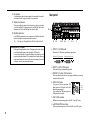
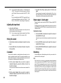
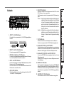
Rear panel
19 18 7
1
3
2
8, 914–17 4–6
10–13
1. INPUT 1–8 (LINE) jacks
These are 1/4" TRS phone-type balanced input jacks.
GND
Balanced TRS phone plug Unbalanced phone plug
COLD
HOT
GND HOT
2. INPUT 1–8 (CD/LINE) jacks
These are RCA-type unbalanced input jacks.
3. PHONO 1–3 jacks, GND terminal
These are phono input jacks for connecting turntables; a grounding
terminal is also provided.
4. MIC1, MIC2 jacks
Two types of jacks are provided: TRS
phone jacks and XLR jacks (with +48V
phantom power supply).
If you connect the TRS phone jacks, the
XLR jacks cannot be used.
5. MIC GAIN switches
48These set the mic preamp gain for the MIC 1 and MIC 2 jacks.
6. +48V PHANTOM switches
These turn phantom power on/off for the MIC 1 and MIC 2 jacks.
2: HOT
1: GND
3: COLD

9
Phantom power is supplied to the balanced XLR jacks.
Note: If you connect or disconnect a condenser mic with the phan-
tom power switch turned on, you risk damaging your equip-
ment. Make sure that the phantom power switch is off before
you connect or disconnect a condenser mic.
Caution
: Never connect any device other than a condenser mic if the
phantom power switch is on. Doing so may damage your
equipment.
7. GUITAR jack
Connect a guitar or bass guitar to this jack.
This is a 1/4" phone-type unbalanced input jack.
8. EXT1 SEND, EXT2 SEND jacks
These jacks output the signal sent from each channel to the external
sends. Connect these jacks to the inputs of your external effect proces-
sors.
9. EXT1 RETURN, EXT2 RETURN jacks
The sound received at the RETURN jacks is mixed into the master bus.
Connect the outputs of your external effect processors to these inputs.
10. BOOTH OUT jacks
These outputs provide the same audio signal as the MASTER OUT
jacks. You can use the BOOTH knob to adjust the BOOTH OUT jacks
to a different level than MASTER OUT.
These are 1/4" TRS phone-type balance output jacks.
11.MASTER OUT (XLR) jacks
These jacks output the audio of the master bus.
12. MASTER OUT (TRS phone) jacks
These jacks output the audio of the master bus.
These are 1/4" TRS phone-type balance output jacks.
13. MASTER OUT output level select switch
This switches the level of the TRS phone MASTER OUT jacks. Set this
to the appropriate position for the equipment you’ve connected.
14. FireWire connector
You can connect the ZERO8 to your computer and use it as an audio/
MIDI interface.
The two connectors operate in the same way. The connector not con-
nected to your computer can be used for daisy-chain connections.
15. DIGITAL OUT (coaxial) jack
This is a S/PDIF type digital output. It outputs the same audio as the
MASTER OUT jacks in digital form.
You can connect this to the input jack of a consumer digital audio de-
vice.
It is an RCA phono-type coaxial jack.
16. MIDI IN connector
This connector receives MIDI messages. Incoming MIDI messages can
be sent to your computer via the FireWire connector.
17. MIDI OUT connector
This connector re-transmits (“thru-es”) the MIDI messages received
from your computer via the FireWire connector. It also transmits MIDI
messages produced by the ZERO8 itself.
18. Power inlet
Connect the included power cable to this connector.
19. Power switch
Turns the power on/off.

10
Connections and Operation
1. Preparations
Before you connect your equipment, you must turn off the power and dis-
connect the power cable from the AC outlet.
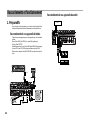
Connecting your output devices
Connecting your input devices
Use the appropriate jacks for the devices you’re connecting.
Mic: MIC jacks (TRS phone jack or balanced XLR jack)
Guitar: GUITAR jack
Sampler, keyboard, etc.: LINE jacks (TRS phone-type balanced input jacks)
CD player: CD/LINE jacks (RCA type unbalanced input jacks)
Turntable: PHONO input jacks and ground connector
Powered Monitors
Master Recorder (Analog input)
PA Mixer
TURNTABLE
GUITAR
MIC
CD PLAYER
X50
R
L/MONO

11
Turning the power on
When powering-on the ZERO8, you must use the following order.
1. Connect the power cable.
Connect the included power cable to the power inlet.
2. Power-on the external equipment that’s connected to
the input jacks.
3. Turn down the ZERO8’s MASTER volume knob.
4. Turn on the power switch located on the ZERO8’s rear
panel.
5. Power-on your monitor amp and the amp that is con-
nected to the MASTER OUT jacks.
Turning the power off
1. Turn down the ZERO8’s MASTER volume knob.
2. Turn off the power of your monitor amp and the amp
connected to the MASTER OUT jacks.
3. Turn off the power switch located on the ZERO8’s rear
panel.
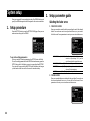
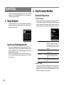
2. Using the mixer
Selecting the inputs
Here’s how to assign a set of input jacks to a specific mixer channel.
1. Use the top panel INPUT SELECTOR knob to select the
desired input.
The knobs of each mixer channel for which you selected an audio in-
put will light orange.
Knobs that are operating as MIDI controllers will light blue.
PHONO 1, 2, 3 Select the sound from the devices
connected to the PHONO 1 jacks,
PHONO 2 jacks, or PHONO 3
jacks respectively.
MIC 1, 2 Select the sound from the devices
connected to the MIC 1 jack or MIC
2 jack respectively.
GUITAR Selects the sound from the device
connected to the GUITAR jack.
LINE Selects the sound of the device con-
nected to the LINE jacks.
CD/LINE Selects the sound of the device con-
nected to the CD/LINE jacks.
FireWire AUDIO Selects the sound from the com-
puter connected to the FireWire
connector.
FireWire AUDIO + MIDI Selects the sound from the com-
puter connected to the FireWire
connector. In this case, the SEND
(EXT 1, EXT 2, ZERO FX SEND)
knobs and PAN knob will operate
as MIDI controllers.
MIDI CONTROL The controllers of the mixer chan-
nel will operate as MIDI control-
lers.

12
TIP: If you’ve selected “FireWire AUDIO” or “FireWire AUDIO
+ MIDI,” the output to the FireWire connector will be the
pre-EQ signal of the source connected to the INPUT (LINE)
jacks.
If you’ve made settings in the SETTING page so that the out-
put of the specified channel is other than “PRE EQ,” “PRE
FDR,” or “POST FDR,” those settings will take priority.
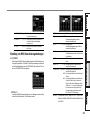
Adjusting the input levels
1. Adjust the GAIN knob.
Adjust this knob so that the level indicator does not light red even
when the maximum level is being input.
TIP: If you’re using mic input and have connected a mic that has
a high level, set the MIC GAIN switch to LOW.
Mixing the sounds
1. Use the fader of each mixer channel to adjust its volume
level.
2. Use the PAN knob of each mixer channel to adjust its
stereo position.
Crossfader
You can use the crossfader to crossfade between the sounds you’ve as-
signed to crossfader channels A and B. By using the crossfader you can
perform DJ techniques such as switching instantly between the sounds of
two channels or crossfading smoothly between them.
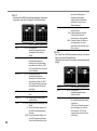
1. For the mixer channel that you want to assign to
crossfader channel A, press the A button to turn it on
(the LED will light).
You may turn on the A button for more than one mixer channel if de-
sired.
2. For the mixer channel that you want to assign to
crossfader channel B, press the B button to turn it on
(the LED will light).
3. To cancel this setting, simply press a lit button once
again.
If a mixer channel is not assigned to either channel A or B (i.e., if nei-
ther of these LEDs are lit), the sound of that mixer channel will be sent
to the master bus without passing through the crossfader.
Master output / Booth output
The mixed sound is output from the MASTER OUT jacks and the BOOTH
OUT jacks.
The same mixed sound is output from both sets of jacks, but you can use
the MASTER knob and BOOTH knob to independently adjust each one to
a different volume.
Adjusting the volume
1. Use the MASTER volume knob to adjust the volume of
the MASTER OUT jacks.
Adjust the volume to a level that does not cause the level meter to light
red.
2. Use the BOOTH volume knob to adjust the volume of
the BOOTH OUT jacks.
3. Use the MONITOR LEVEL knob to adjust the volume of
the headphones.
Monitoring
Connect headphones to the headphone jack so that you can refer to the
mixed sound or the audio inputs.
CUE
This function lets you monitor your performance through headphones
without outputting it from the MASTER OUT jacks. To monitor the sound
of the CUE bus through headphones, turn the monitor section MONITOR
BAL knob toward the CUE position. In this state, you can leave a fader
lowered but turn CUE on and use your headphones to check the sound
adjusted by EQ and the channel effect; then when you’ve adjusted the
sound to your liking, raise the channel fader to output the sound from the
master outputs.

13
Monitoring via CUE
By turning on the CUE button of a mixer channel, you can send its pre-
fader sound to the CUE bus.
1. Turn on the CUE button of the mixer channel you want
to monitor.
2. Use the MONITOR BAL knob to adjust the volume bal-
ance of the master output sound and the CUE bus
sound.
Use the MONITOR LEVEL knob to adjust the overall volume.
Adjusting the effect levels
If you’re using external effect processors, connect them to the EXT 1/2
SEND jacks and EXT 1/2 RETURN jacks.
1. Use each mixer channel’s EXT 1 and EXT 2 SEND knobs
to adjust the send levels that are output to the SEND
jacks.
Use the EXT 1 and EXT 2 RETURN knobs to adjust the return levels
that are received from the RETURN 1 and RETURN 2 jacks.
2. Use each mixer channel’s ZERO FX SEND knobs to ad-
just the send level to the (built-in) send effect.
Use the ZERO FX SEND RETURN knob to adjust the return level from
the send effect.
TIP: The CUE buttons for the EXT1, EXT 2, and ZERO FX re-
turns introduce their respective signals to the CUE bus before
the it passes through the return level knobs.
Set the return level to zero and turn the CUE button on (lit).
Now you’ll be able to use headphones (set to CUE) to adjust
the return sound. When you’ve adjusted the sound to your
liking, raise the EXT1, EXT2 or ZERO FX return level knobs
to send the signal to the master outputs.
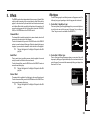
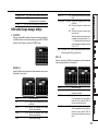
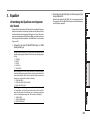
3. Equalizer
Using the equalizer to adjust the sound
Traditionally, an equalizer (EQ) divides the sound into different frequency
regions, allowing you to shape the tonal character of the sound by boost-
ing or cutting the output of each region. In more modern applications, the
EQ can be used as an effect, providing filter sweeps and isolator functions.
The ZERO8 provides 11 different types of EQ.
1. Use the EQ SELECTOR knob to select the equalizer
type.
EQ type: These are a variety of EQ types with frequency re-
sponses suitable for different styles. Choose the type that’s ap-
propriate for your needs.
A ZERO EQ
B BOOST
C HYPED
D ROUND-Q
E SLAMMING
ISOLATOR type: This is a -12dB/oct isolator. It divides the in-
put sound into frequency regions, and allows you to individu-
ally cut the sound of each region. If you turn the knobs of all re-
gions completely toward the left, the sound will disappear com-
pletely.
F ZERO ISOLATOR
G ZERO ISOLATOR WIDE DIVIDER
H ZERO ISOLATOR LOW
FILTER type: These are filter types in which HI is an LPF and LO
is a HPF. Turning HI down (toward the left) will lower the cutoff
frequency of the LPF. Turning LO down (toward the left) will
raise the cutoff frequency. MID operates as a peaking EQ.
I ZERO FILTER
J ZERO FILTER DENSE
K ZERO FILTER SPIKY
2. Use the EQ knobs to control the type of EQ you se-
lected.
Adjust the three bands (HI/MID/LO) to obtain the desired tone.
The MID-FREQ knob sets the center frequency of the MID region.

14
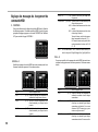
4. BPM system
In the ZERO8, the BPM (Beats Per Minute) setting is used as the master
clock for MIDI and for effects that are synchronized to the BPM. The
ZERO8 has an Auto BPM function that automatically detects the BPM from
an audio input source. You can also set the BPM manually.
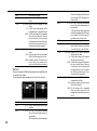
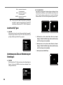
Setting the BPM manually
1. Press the BPM button to access the BPM page.
2. Turn push-knobs 7 and 8 to set the desired BPM.
By turning push-knob 8 you can adjust the BPM in fine steps of 0.01.
Setting the BPM using tap tempo
Press the TAP button at least three times to the beat of the song. The inter-
val at which you pressed the button will be calculated, and specified as the
BPM value.
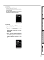
Setting the BPM automatically
Here’s how you can use the Auto BPM Counter to detect the BPM of a song
that’s being input.
1. Press the BPM button to access the BPM page.
2. In the LCD display, press 1–8 or the MASTER button to
select the source whose BPM you want to detect.
If you select 1–8, the BPM will be detected from the sound of the cor-
responding channel.
If you select MASTER, the BPM will be detected from the mixed sound
of all channels.
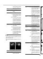
3. In the LCD display, press the AUTO BPM button to turn
AUTO BPM on; automatic BPM detection will begin.
If the BPM is detected incorrectly, you can leave AUTO BPM turned
on, and press the TAP button at the beat of the song; the BPM will be
automatically detected using your manual tapping as a guideline.
While AUTO BPM is on, the BPM will continue to be adjusted auto-
matically even if the BPM of the audio input is changing.
TIP: By pressing the AUTO BPM button on the panel, you can
turn AUTO BPM on/off even when you’re not in the BPM
page.
TIP: The BPM cannot be detected correctly for songs that don’t
have a definite beat.

15
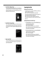
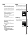
5. Effects
The ZERO8 provides three independent effect processors: a Channel Effect
which is used by inserting it into a mixer channel, a Send Effect which is
applied to the sound sent by the send level knob of each mixer channel,
and a Master Effect which is applied to the final stage of the master bus. To
access the setting pages for each of these effects, press the CHANNEL,
SEND, or MASTER buttons in the ZERO FX section.
Channel Effect
The channel effect is used by inserting it into a mixer channel, where it will
process only the audio input of that channel.
To select the channel effect, press the CHANNEL button of the ZERO FX
section to access the channel effect page. When the channel effect page is
displayed, you can select the channel to which the effect will be applied.
TIP: The page that appears in the display will depend on the effect
program.
Send Effect
This is a send/return type effect processor, which is applied to the sound
sent by the send level knob of each mixer channel.
To select the send effect, press the SEND button of the ZERO FX section to
access the send effect page.
TIP: The page that appears in the display will depend on the effect
program.
Master Effect
The master effect is applied at the final stage to the overall mixed sound.
To select the master effect, press the MASTER button of the ZERO FX sec-
tion to access the master effect page.
TIP: The page that appears in the display will depend on the effect
program.
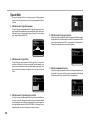
Effect types
The effect setting page for each effect processor will appear as one of the
following five types, depending on the effect program that is selected.
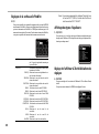
1: Touch effect 1 (eight-bar type)
This is an eight-bar type effect program page that you can control by draw-
ing in the touch area in the lower part of the page. Use your finger to
“draw” the gain curve for each band of the 8BAND EQ.
2: Touch effect 2 (filter type)
This is a filter-type effect program page where you can control the cutoff
frequency by sliding your finger horizontally in the touch area in the lower
part of the page. You can control the resonance by sliding your finger in the
direction of the Y-axis.

16
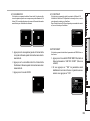
3: Touch effect 3 (eight-pad type)
This is a eight-pad type effect program page that you can control by press-
ing the eight pads shown in the touch area in the lower part of the page. By
pressing the desired Beat setting of the LOOP DELAY effect, you can in-
stantly switch the delay time’s beat value.
4: Touch effect 4 (touch pad type)
This is a touch-pad type effect program page in which the entire page is a
touch area. Different effect parameters can be assigned to the X-axis and Y-
axis, allowing you to control two parameters simultaneously with a single
operation.
5: Knob control effect
This is an effect program page that does not use touch pad operations. You
can control up to six effect parameters assigned to the push-knobs by turn-
ing the corresponding knob.
Operating the effects
Operating the touch effect types
In touch effect pages 2–4, you can turn the HOLD button on (LED lit) to
maintain the current state of the effect.
HOLD on (LED lit): Hold will be enabled for the touch effect.
When you take your finger off the touch pad, the effect will remain in the
state in which you had last been touching the pad.
HOLD off (LED dark): Hold will be disabled for the touch effect.
When you take your finger off the touch pad, the effect sound will be com-
pletely “dry.”
Operating the knobs for each effect type
1. For touch effect types 1–4, you can use the knobs to per-
form the following operations.
Knob 1: Selects the effect program
Knob 4: Selects the effect channel when using a channel effect
Knobs 5–8: Edit the effect parameters (the parameters that can be ed-
ited will depend on the effect program)
2. For knob control effect type 5, you can use the knobs to
perform the following operations.
Knob 1: Selects the effect program
Knob 2: Selects the effect channel when using a channel effect
Knobs 3–8: Edit the effect parameters (the parameters that can be ed-
ited will depend on the effect program)

17
FireWire interface functions
You can connect the ZERO8 to your computer via a FireWire cable and use
it as an audio/MIDI interface.
Note: This device does not supply bus power.
Note: Do not simultaneously connect more than one computer to
the ZERO8.
Note: If you are using a host application such as sequencing soft-
ware, you’ll need to make audio and MIDI device settings.
For details, refer to the owner’s manual of the software you’re
using.
Note: You must connect the ZERO8 to your computer using a
FireWire cable and turn on the power before you start up your
software. Don't disconnect the FireWire cable or power-off
the ZERO8 while the software is running.
Note: If you're using the ZERO8 with Mac OS X, turn off the Sleep
setting and power management settings.
Note: Each input/output device can be used with only one software
application. Multi-client operation is not supported.
Note: Use the included CD-ROM to install the “KORG FireWire
Audio/MIDI driver” into the computer you're using. (☞
p.27)
1. FireWire audio interface
You can use the ZERO8 as an audio interface. This lets you send the
ZERO8’s audio inputs or mixed sound to your computer, and send the
audio outputs from a host application on your computer to the ZERO8.
Your FireWire-connected computer will detect the ZERO8 as an audio in-
terface that provides a maximum of 16-in and 16-out audio streams.
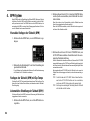
Limitations for different sampling rates
If the ZERO8 is connected to your computer, you’ll be able to change the
sampling rate from the control panel of the host application or audio
driver. The available number of effects and mixer channels will depend on
the sampling rate you select.
44.1 kHz or 48 kHz: Eight stereo channels + the internal effects
(ZERO FX CHANNEL, SEND, MASTER)
96 kHz: Eight stereo channels
Note: When operating at 96 kHz, the internal effects (ZERO FX
CHANNEL, SEND, MASTER) and the channel EQ for
channels 5–8 will not be available. Nor will you be able to use
the EXT1 or EXT2 RETURN jacks.
Note: When using the ZERO8 with Mac OS X
Depending on the system you’re using, you may experience
problems such as the operating system becoming unstable
when you switch the sampling frequency.
If this occurs, you can start up as described below so that the
ZERO8 will operate with a fixed sampling frequency. In this
case, you won't be able to switch to another sampling fre-
quency from the computer.
44.1 kHz: Turn on the power while holding down the mixer
channel 1 Cue button.
48 kHz: Turn on the power while holding down the mixer
channel 2 Cue button.
96 kHz: Turn on the power while holding down the mixer
channel 3 Cue button.
In the Mac OS System Settings / Sound / Output dialog box,
verify that the ZERO8 has disappeared from the list of sound
output devices, and then turn the power on once again.
Depending on the type of computer you’re using, starting up
the computer with the ZERO8 already connected may cause
operation to become unstable. In this case, connect the
ZERO8 after the computer has started up.

18
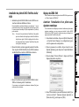
Using the ZERO8 at the 192 kHz sampling rate
By starting up the ZERO8 in the special 192 kHz audio mode, you can use
it as a high-quality 24-bit/192 kHz 8-in/8-out audio interface.
Note: When using Mac OS X, the 192 kHz sampling rate is not
supported.
Starting up in 192 kHz audio mode
While holding down the SETUP button, turn on the power.
Note: If you start up in 192 kHz audio mode, you won’t be able to
switch to other sampling rates (44.1 kHz, 48 kHz, 96 kHz).
If you want to switch to a different sampling rate, you must
turn off the power and then turn the power on again to start
up in the normal way.
Limitations in 192 kHz audio mode
The specifications are limited as follows when operating in the special 192
kHz mode.
• Number of channels: Four stereo channels (8-in/8-out)
• Channel EQ: Not available
• EXT 1, EXT 2 SEND/RETURN: Not available
• Internal effects (CH, SEND, MASTER): Not available
Controller operation when in 192 kHz audio mode
Channel controller
CH1–4 CH5–8
INPUT SELECTOR Operates normally Not available
GAIN Operates normally Not available
EQ SELECTOR MIDI controller MIDI controller
(transmits program change messages)
HI MIDI controller MIDI controller
MID-FREQ MIDI controller MIDI controller
MID MIDI controller MIDI controller
LO MIDI controller MIDI controller
PAN MIDI controller MIDI controller
EXT1(SEND) MIDI controller MIDI controller
EXT2(SEND) MIDI controller MIDI controller
ZERO FX SEND MIDI controller MIDI controller
SOLO Operates normally MIDI controller
MUTE Operates normally MIDI controller
CUE Operates normally MIDI controller
A Operates normally MIDI controller
B Operates normally MIDI controller
CH FADER Operates normally MIDI controller
Master controllers
CROSSFADER Operates normally
EXT1(RETURN) Not available
EXT1(RETURN) CUE Not available
EXT2(RETURN) Not available
EXT2(RETURN)CUE Not available
ZERO FX(RETURN) Not available
ZERO FX(RETURN)CUE Not available
MONITOR BAL Operates normally
MONITOR LEVEL Operates normally
BOOTH Operates normally
MASTER Operates normally

19
2. FireWire MIDI interface
A MIDI device connected to the ZERO8’s MIDI IN/OUT connectors can
communicate with your computer via the FireWire connector.
About MIDI
MIDI stands for Musical Instrument Digital Interface, and is a world-wide
standard that allows electronic musical instruments and computers to ex-
change a wide variety of performance-related information.
About the MIDI implementation chart
The owner’s manual of each MIDI device includes a “MIDI implementa-
tion chart.” This chart makes it easy to determines the types of MIDI mes-
sages that each device is able to transmit or receive. When using two MIDI
devices, you can compare their MIDI implementation charts to see
whether the messages transmitted by one device will be recognized by the
other device. The MIDI implementation chart for this device is provided on
the CD-ROM.
Note: Details of the MIDI functionality are provided in the MIDI
implementation, which can be found on the included CD-
ROM.
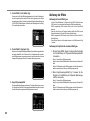
Using the ZERO8 as a MIDI controller
In addition to functioning as a mixer, the ZERO8 can also be used as a
realtime controller that transmits MIDI messages to control an application
on your computer or an external MIDI device such as a synthesizer.
Connecting to your computer
1. Install the MIDI driver.
Use the included CD-ROM to install the “KORG FireWire Audio/
MIDI driver” in your computer. (☞p.27)
TIP: If you’re using a Macintosh, you don’t need to install a driver.
2. Use a FireWire cable to connect the ZERO8 to your com-
puter.
3. Make sure that your computer has detected the ZERO8.
4. Start up your host application.
Note: When you connect the ZERO8 to your computer via a
FireWire cable, it will be detected as a “3-in/3-out” MIDI
interface. In this connection, “ZERO 1” is used to commu-
nicate between the ZERO8 and the included “ZERO Edit”
editor software. “ZERO 2” is used to exchange MIDI mes-
sages between the ZERO8 and your MIDI host application
such as a DAW. “ZERO 3” will operate as a MIDI interface
used to exchange messages with an external MIDI device con-
nected to the ZERO8’s MIDI connectors. (☞p.20)
Note: Depending on the DAW or other MIDI host application
you’re using, the application may allocate all of the MIDI
ports when it is started-up.
If you want to use this type of application at the same time
as the “ZERO Edit” editor for the ZERO8, you must start
up ZERO Edit first and allow it to detect and connect the
“ZERO 2” MIDI port. Then start up your MIDI host appli-
cation, and you’ll be able to use the ZERO Edit software and
your other application at the same time.
Using the controllers of the mixer channels as MIDI controllers
1. Turn the INPUT SELECTOR knob to MIDI.
For the mixer channel you want to use as a controller, turn the INPUT
SELECTOR knob to the MIDI position.
2. When you operate the knobs/switches of the selected
mixer channel, the MIDI control messages assigned to
each controller will be transmitted.
At this time, the audio received at the LINE input jacks of the selected
mixer channel will be output to the master bus. However, you won’t be
able to adjust the fader, EQ, or balance. Use the GAIN knob to adjust
the volume.
3. You can use the dedicated ZERO Edit editor software
(or the System Setup>MAIN>CONTROL page) to
change the MIDI messages assigned to each controller.

20
Using push-knobs 1–8 and the touch pad as MIDI controllers
You can use push-knobs 1–8 and the touch pad (LCD display) as MIDI
controllers. Assignments for these controllers can be stored in the BANK 1–
4 buttons, and recalled simply by pressing a button.
1. Press the BANK 1 button to access the MIDI control
bank page. The BANK 1 button will light.
2. When you turn a push-knob 1–8, the MIDI message as-
signed to the respective encoder operation will be trans-
mitted.
3. When you push a push-knob 1–8, the MIDI message as-
signed to the respective switch operation will be trans-
mitted.
4. When you touch the LCD display (touch pad), the MIDI
messages assigned to touch, X-axis, and Y-axis opera-
tions will be transmitted.
5. You can use System Setup or the ZERO Edit application
to change these MIDI messages.
6. In the same way as for BANK 1, you can access the
BANK 2 – 4 pages and transmit the MIDI messages that
are assigned to the controllers in those banks.
FireWire Audio/MIDI device name list
MIDI Device
PortNo MIDI IN MIDI OUT Remarks
1 ZERO 1 ZERO 1 Only for ZERO Edit
2 ZERO 2 ZERO 2 Only for MIDI control-
lers
3 ZERO 3 ZERO 3 For external MIDI IN/
OUT connectors
Note: Depending on the application you’re using, the application
may display its own port name rather than obtaining the
name from the ZERO8.
Audio Device
PortNo Audio Input Corresponds to input jack
Audio Output Corresponds to output jack
(factory settings*1)
1 ZERO 1L CH 1 L
ZERO 1L CH 1 L PRE EQ
2 ZERO 1R CH 1 R
ZERO 1R CH 1 R PRE EQ
3 ZERO 2L CH 2 L
ZERO 2L CH 2 L PRE EQ
4 ZERO 2R CH 2 R
ZERO 2R CH 2 R PRE EQ
5 ZERO 3L CH 3 L
ZERO 3L CH 3 L PRE EQ
6 ZERO 3R CH 3 R
ZERO 3R CH 3 R PRE EQ
7 ZERO 4L CH 4 L
ZERO 4L CH 4 L PRE EQ
8 ZERO 4R CH 4 R
ZERO 4R CH 4 R PRE EQ
9 ZERO 5L CH 5 L
ZERO 5L CH 5 L PRE EQ
10 ZERO 5R CH 5 R
ZERO 5R CH 5 R PRE EQ
11 ZERO 6L CH 6 L
ZERO 6L CH 6 L PRE EQ
Seite laden ...
Seite laden ...
Seite laden ...
Seite laden ...
Seite laden ...
Seite laden ...
Seite laden ...
Seite laden ...
Seite laden ...
Seite laden ...
Seite laden ...
Seite laden ...
Seite laden ...
Seite laden ...
Seite laden ...
Seite laden ...
Seite laden ...
Seite laden ...
Seite laden ...
Seite laden ...
Seite laden ...
Seite laden ...
Seite laden ...
Seite laden ...
Seite laden ...
Seite laden ...
Seite laden ...
Seite laden ...
Seite laden ...
Seite laden ...
Seite laden ...
Seite laden ...
Seite laden ...
Seite laden ...
Seite laden ...
Seite laden ...
Seite laden ...
Seite laden ...
Seite laden ...
Seite laden ...
Seite laden ...
Seite laden ...
Seite laden ...
Seite laden ...
Seite laden ...
Seite laden ...
Seite laden ...
Seite laden ...
Seite laden ...
Seite laden ...
Seite laden ...
Seite laden ...
Seite laden ...
Seite laden ...
Seite laden ...
Seite laden ...
Seite laden ...
Seite laden ...
Seite laden ...
Seite laden ...
Seite laden ...
Seite laden ...
Seite laden ...
Seite laden ...
Seite laden ...
Seite laden ...
Seite laden ...
Seite laden ...
Seite laden ...
Seite laden ...
Seite laden ...
Seite laden ...
Seite laden ...
Seite laden ...
Seite laden ...
Seite laden ...
Seite laden ...
Seite laden ...
Seite laden ...
Seite laden ...
Seite laden ...
Seite laden ...
Seite laden ...
Seite laden ...
Seite laden ...
Seite laden ...
Seite laden ...
Seite laden ...
-
 1
1
-
 2
2
-
 3
3
-
 4
4
-
 5
5
-
 6
6
-
 7
7
-
 8
8
-
 9
9
-
 10
10
-
 11
11
-
 12
12
-
 13
13
-
 14
14
-
 15
15
-
 16
16
-
 17
17
-
 18
18
-
 19
19
-
 20
20
-
 21
21
-
 22
22
-
 23
23
-
 24
24
-
 25
25
-
 26
26
-
 27
27
-
 28
28
-
 29
29
-
 30
30
-
 31
31
-
 32
32
-
 33
33
-
 34
34
-
 35
35
-
 36
36
-
 37
37
-
 38
38
-
 39
39
-
 40
40
-
 41
41
-
 42
42
-
 43
43
-
 44
44
-
 45
45
-
 46
46
-
 47
47
-
 48
48
-
 49
49
-
 50
50
-
 51
51
-
 52
52
-
 53
53
-
 54
54
-
 55
55
-
 56
56
-
 57
57
-
 58
58
-
 59
59
-
 60
60
-
 61
61
-
 62
62
-
 63
63
-
 64
64
-
 65
65
-
 66
66
-
 67
67
-
 68
68
-
 69
69
-
 70
70
-
 71
71
-
 72
72
-
 73
73
-
 74
74
-
 75
75
-
 76
76
-
 77
77
-
 78
78
-
 79
79
-
 80
80
-
 81
81
-
 82
82
-
 83
83
-
 84
84
-
 85
85
-
 86
86
-
 87
87
-
 88
88
-
 89
89
-
 90
90
-
 91
91
-
 92
92
-
 93
93
-
 94
94
-
 95
95
-
 96
96
-
 97
97
-
 98
98
-
 99
99
-
 100
100
-
 101
101
-
 102
102
-
 103
103
-
 104
104
-
 105
105
-
 106
106
-
 107
107
-
 108
108


Korg ZERO 8 Bedienungsanleitung
- Kategorie
- Musikinstrumente
- Typ
- Bedienungsanleitung
- Dieses Handbuch ist auch geeignet für
in anderen Sprachen
- English: Korg ZERO 8 Owner's manual
- français: Korg ZERO 8 Le manuel du propriétaire
Verwandte Papiere
Sonstige Unterlagen
-
M-Audio FireWire Solo Bedienungsanleitung
-
Pioneer DJM-400 Bedienungsanleitung
-
-
Reloop Elite Bedienungsanleitung
-
Pioneer DJM-850-W Benutzerhandbuch
-
Behringer NOX303 Schnellstartanleitung
-
Denon DN-X1500S - DJ Mixer Bedienungsanleitung
-
Behringer XENYX UFX1204 Schnellstartanleitung
-
Hama 00052213 Bedienungsanleitung
-