Bresser 7060200 Bedienungsanleitung
- Kategorie
- Wetterstationen
- Typ
- Bedienungsanleitung
Dieses Handbuch eignet sich auch für

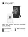
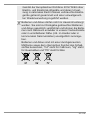
Weather Station · Wetterstation · Station météo · Estación meteo-
rológica · Weerstation ·
ClimaTemp FSX
EN Instruction manual
DE Bedienungsanleitung
FR Mode d’emploi
ES Manual de instrucciones
NL Gebruikershandleiding

DE
Besuchen Sie unsere Website über den folgenden QR Code oder Weblink um weitere Informationen
zu diesem Produkt oder die verfügbaren Übersetzungen dieser Anleitung zu finden.
EN
Visit our website via the following QR Code or web link to find further information on this product or
the available translations of these instructions.
FR
Si vous souhaitez obtenir plus d’informations concernant ce produit ou rechercher ce mode
d’emploi en d’autres langues, rendez-vous sur notre site Internet en utilisant le code QR ou le lien
correspondant.
NL
Bezoek onze internetpagina via de volgende QR-code of weblink, voor meer informatie over dit
product of de beschikbare vertalingen van deze gebruiksaanwijzing.
ES
¿Desearía recibir unas instrucciones de uso completas sobre este producto en un idioma determinado?
Entonces visite nuestra página web utilizando el siguiente enlace (código QR) para ver las versioneAs
disponibles.
IT
Desidera ricevere informazioni esaustive su questo prodotto in una lingua specifica? Venga a
visitare il nostro sito Web al seguente link (codice QR Code) per conoscere le versioni disponibili.
www.bresser.de/P7060200
www.bresser.de/warranty_terms
GARANTIE · WARRANTY · GARANTÍA · GARANZIA


4 / 108
1 Imprint
Bresser GmbH
Gutenbergstr. 2
46414
Rhede
Germany
www.bresser.de
For any warranty claims or service enquiries, please refer to
the information on "Warranty" and "Service" in this docu-
mentation. We apologize for any inconvenience caused by
the fact that we cannot process enquiries or submissions
sent directly to the manufacturer's address.
Errors and technical changes excepted.
© 2021 Bresser GmbH
All rights reserved.
The reproduction of this documentation - even in extracts -
in any form (e.g. photocopy, print, etc.) as well as the use
and distribution by means of electronic systems (e.g. image
file, website, etc.) without the prior written permission of the
manufacturer is prohibited.
The designations and brand names of the respective com-
panies used in this documentation are generally protected
by trade, trademark and/or patent law in Germany, the
European Union and/or other countries.
2 Validity note
This documentation is valid for the products with the follow-
ing article numbers:
7060200

5 / 108
Manual version: 0521
Manual designation:
Manual_7060200_ClimaTemp-FSX_en-de-fr-es-
nl_BRESSER_v052021a
Always provide information when requesting service.
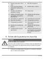
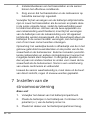
3 About this Instruction Manual
NOTICE
These operating instructions are to be considered a
component of the device.
Read the safety instructions and the operating manual care-
fully before using this device.
Keep this instruction manual in a safe place for future refer-
ence. When the device is sold or given to someone else,
the instruction manual must be provided to the new owner/
user of the product.

6 / 108
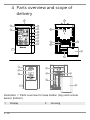
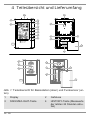
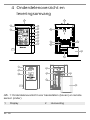
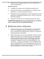
4 Parts overview and scope of
delivery
BARO
CH
12/24
2
1
3
4
5
6
7
8
9
10
11
3
14
15
16
12
13
19
18
17
22
21
24
23
20
A
B
Illustration1: Parts overview for base station (top) and remote
sensor (bottom)
1 Display 2 Housing

7 / 108
3 SNOOZE/LIGHT button
(snooze function and tem-
porary background lighting)
4 HISTORY button (retrieve
measurements for the past
24 hours)
5 CH/UP button (sensor chan-
nel selection or value change
upwards)
6 12/24/DOWN button (time
mode selection or value
change downwards)
7 MAX/MIN button (switch
between highest, lowest or
current value display)
8 BARO button (display of dif-
ferent atmospheric pressure
values)
9 TIME button (manual time
setting)
10 ALARM button (Alarm set-
ting)
11 Wall mount fixture 12 °C/°F button (temperature
format setting)
13 RESET button (reset all set-
tings)
14 Stand, fold-out
15 Battery compartment cover 16 Battery compartment
17 Display 18 Function indicator (data
transmission)
19 Housing 20 Battery compartment
21 RESET button (reset all set-
tings)
22 Wall mount fixture
23 Channel switch 24 Battery compartment cover
Scope of delivery
Base station (A), remote sensor (B)
Also required (not included):
4 pcs. Mignon batteries (1.5V, AA type)

8 / 108
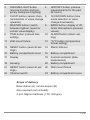
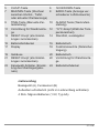
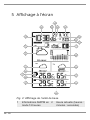
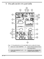
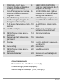
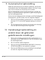
5 Screen display
1
2
5
6
3
4
8
10
9
11
12
7
13
14
21
22
20
17
18
19
16
15
Illustration2: Display of the base unit
1 AM/PM information in
12-hour time mode
2 Current time
(hours:minutes:seconds)
3 Alarm symbol (alarm 1
or 2 enabled)
4 Symbol for active day-
light saving time (DST)

9 / 108
5 Date (month-day or re-
verse)
6 Weekday
7 Transmission symbol
(radio-controlled clock
CET)
8 Alarm (AL1 or AL2)
9 Air pressure (mb/hPa or
inHg)
10 Moon phase
11 Bar chart for air pres-
sure history
12 Weather trend (72
hours)
13 Humidity outdoors 14 Humidity indoors
15 Battery status 16 Temperature (indoor)
17 Temperature (outdoor) 18 Channel info (sensors)
19 Sensor signal status 20 Weather trend (48
hours)
21 Weather trend (24
hours)
22 Singles values for air
pressure history (up to
24 hours)
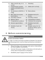
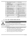
6 Before commissioning
NOTICE
Avoid connection faults!
In order to avoid connection problems between the devices,
the following points must be observed during commission-
ing.
1. Place the base unit (receiver) and sensor (transmitter)
as close together as possible.
2. Connect the power supply to the base unit and wait un-
til the indoor temperature is displayed.
3. Establish power supply for the sensor.

10 / 108
4. Set up/operate the base unit and sensor within the ef-
fective transmission range.
5. Make sure that the base unit and the radio sensor are
set to the same channel.
When changing the batteries, always remove the batteries
in both the base unit and the sensor and reinsert them in
the correct order so that the radio connection can be re-es-
tablished. If one of the two devices is operated via a mains
power connection, the power connection for this device
must also be disconnected briefly when changing the bat-
tery. If, for example, only the batteries in the sensor are re-
placed, the signal cannot be received or can no longer be
received correctly.
Note that the actual range depends on the building materi-
als used in the building and the position of the base unit and
outdoor sensor. External influences (various radio transmit-
ters and other sources of interference) can greatly reduce
the possible range. In such cases, we recommend finding
other locations for both the base unit and the outdoor
sensor. Sometimes a shift of just a few centimetres is
enough!
Though the remote unit is weather proof, it should be placed
away from direct sunlight, rain or snow.
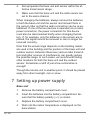
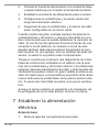
7 Setting up power supply
Base unit
1. Remove the battery compartment cover.
2. Insert the batteries into the battery compartment. En-
sure that the battery polarity (+/-) is correct.
3. Replace the battery compartment cover.
4. Wait until the indoor temperature is displayed on the
base station.

11 / 108
Remote sensor
5. Remove the battery compartment cover.
6. Insert the batteries into the battery compartment. En-
sure that the battery polarity (+/-) is correct.
7. Move the CH slide control to the position for the desired
transmission channel (setting CH1, CH2 or CH3 with
screen display).
8. Replace the battery compartment cover.
NOTICE!When operating one outdoor sensor, channel 1
is recommended as the default setting.
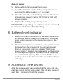
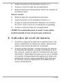
8 Battery level indicator
1. When the level of the batteries in the base station or in
the wireless sensor reaches a critical level, the battery
level symbol appears in the appropriate area on the
display.
2. When replacing one set of batteries, always remove the
batteries from the other part of the unit and reinsert
them in the correct order (see chapter "Setting up
power supply"). Replace the batteries to be changed in
the corresponding part of the device with a completely
new set with full capacity. This ensures that the con-
nection between the devices will be reestablished again
correctly.
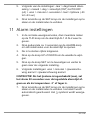
9 Automatic time setting
After the power supply was established, the clock will auto-
matically search for the radio signal. This will take approxim-
ately 3 to 8 minutes to finish this process.

12 / 108
If the radio signal is received correctly, the date and time
will be set automatically and the radio control signal icon
turns on.
If the clock fails to receive the time signal, go ahead with the
following steps:
1. Press °C/°F button on the base station for approx. 3
seconds to initate RC signal reception again.
2. If the device is still not receiving the signal, the time
must be set manually.
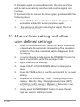
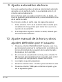
10 Manual time setting and other
user defined settings
1. Press the SNOOZE/LIGHT button for about 8 seconds
to deactivate the automatic time setting. The reception
symbol for the radio-controlled watch disappears from
the display.
2. In normal display mode, press the TIME SET button for
about 2 seconds to enter the settings mode.
3. Digits to be set are flashing.
4. Press CH/UP or 12/24/DOWN button to change the
value.
5. Press the TIME button to confirm and switch to the next
setting.
6. Sequence of the settings: Year > Change day/month
display > Month > Day > Daylight saving time (DST)
AUTO/OFF (off) > Hours > Minutes > Seconds > Lan-
guage > Time zone (-23 to +23 hours)
7. Finally press the MODE/SET button to save the set-
tings and exit the settings mode.

13 / 108
8. NOTICE!To restore the automatic time setting,
press the SNOOZE/LIGHT button again for 8
seconds. The reception symbol for the radio-con-
trolled watch reappears in the display.
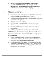
11 Alarm settings
1. In normal display mode, press the TIME button several
times to display the Alarm time AL1 or AL2.
2. Press ALARM button for approx. 3 seconds to enter the
alarm time setting mode.
3. Digits to be set are flashing.
4. Press CH/UP or 12/24/DOWN button to change the
value.
5. Press ALARM button to confirm and continue to the
next setting.
6. Settings order: hours > minutes > ice alert on/off
NOTICE!If ice alert is enabled (on), the alarm will sound
30 seconds before the set alarm time if the temperature
is -3° or below.
7. Finally press the ALARM button to save the settings
and exit the setting mode. Alarm will be activated auto-
matically. The
symbol will be displayed.
8. In normal display mode, press the ALARM button sev-
eral times to enable alarm time AL1, AL2 or both. If the
alarm is enabled, the corresponding symbol will be dis-
played (
1, 2 or 1 2).

14 / 108
12 Snooze function
1. When the alarm sounds press the SNOOZE/LIGHT but-
ton to activate the snooze function. The alarm will
sound again in 5 minutes.
2. Press ALARM button when the alarm sounds to inter-
rupt the alarm until the alarm time will be reached
again.
3. The alarm will be turned off automatically if no button is
pressed within 2 minutes.
13 Receiving measurements
automatically
Once the power supply is enabled, the base station will dis-
play the measurement readings for indoors. Readings from
the outdoor sensor will be displayed within 3 minutes after
powering it on.
If no signal is received, proceed as follows:
Press 12/24 button for approx. 3 seconds to initate recep-
tion of measurements again.
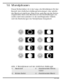
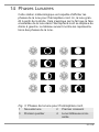
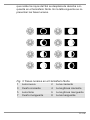
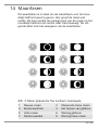
14 Moon phases
This weather station is able to display the moon phases for
the northern hemisphere. Here the moon grows from the
right. This is because the sunlit side of the moon in the
northern hemisphere moves from right to left. The following
table shows the representations of the moon phases.

15 / 108
1
2
3
4
5
6
7
8
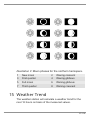
Illustration3: Moon phases for the northern hemispere.
1 New moon 2 Waxing crescent
3 First quarter 4 Waxing gibbous
5 Full moon 6 Waning gibbous
7 Third quarter 8 Waning crescent
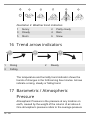
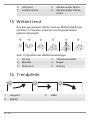
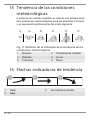
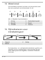
15 Weather Trend
The weather station will calculate a weather trend for the
next 12 hours on basis of the measured values.

16 / 108
1
2
3
4
5
6
Illustration4: Weather trend indicators
1 Sunny 2 Partly cloudy
3 Cloudy 4 Rain
5 Storm 6 Snow
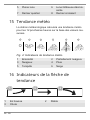
16 Trend arrow indicators
1
2
3
1 Rising 2 Steady
3 Falling
The temperature and humidity trend indicator shows the
trends of changes in the forthcoming few minutes. Arrows
indicate a rising, steady or falling trend.
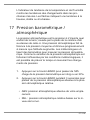
17 Barometric / Atmospheric
Pressure
Atmospheric Pressure is the pressure at any location on
earth, caused by the weight of the column of air above it.
One atmospheric pressure refers to the average pressure

17 / 108
and gradually decreases as altitude increases. Meteorolo-
gists use barometers to measure atmospheric pressure.
Since variation in atmospheric pressure is greatly affected
by weather, it is possible to forecast the weather by measur-
ing the changes in pressure.
1. Press the BARO button to switch between barometric
pressure display in inHg or in hPa.
2. Press the BARO button for 3 seconds to change
between absolute and relative atmospheric pressure.
• ABSOLUTE: the absolute atmospheric pressure of your
location.
• RELATIVE: the relative atmospheric pressure based on
the sea level.
Set relative atmospheric pressure value
3. Get the atmospheric pressure data of the sea level (it is
also the relative atmospheric pressure data of your
home area) through the local weather service, internet
and other channels.
4. Press and hold the BARO button for approx. 3 seconds
until "abs" or "rel" flashes.
5. Press CH/UP or 12/24/DOWN button to switch to "rel"
mode.
6. Press the BARO button and the number for "rel"
flashes.
7. Press CH/UP or 12/24/DOWN button to change the
value.
8. Press the BARO button to save and exit the setting
mode.

18 / 108
NOTE
9. The default relative atmospheric pressure value is 1013
mb/hPa (29.91 inHg), which refers to the average at-
mospheric pressure.
10. When you change the relative atmospheric pressure
value, the weather indicators will change along with it.
11. The built-in barometer can notice the environmental ab-
solute atmospheric pressure changes. Based on the
collected data a forecast for the weather conditions in
the next 12 hours can be made. Therefore, the weather
indicators will change according to the detected abso-
lute atmospheric pressure after you operate the clock
for 1 hour.
12. The relative atmospheric pressure is based on the sea
level, but it will change with the absolute atmospheric
pressure changes after operating the clock for 1 hour.
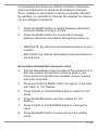
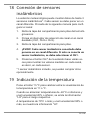
18 Connecting remote sensors
The Weather Station can display the readings from up to 3
wireless sensors* of the same type. Each radio sensor must
be set to a separate channel. Proceed as follows to set the
channel:
1. Remove the battery compartment cover of the wireless
sensor.
2. Set the channel selection switch to the desired channel
(CH1, CH2 or CH3).
3. Re-attach the battery compartment cover.
4. NOTICE!Each connected wireless sensor must be set
to a different channel. If only one wireless sensor is
connected, it should be set to CH1.

19 / 108
5. Press the CH/UP button on the base station several
times to display the measured values for the individual
channels. The selected channel is shown in the display.
• one wireless sensor included, others optionally available
19 Temperature display
Press the °C/°F button to switch between the temperature
display in °C or °F.
When temperatures of -40°C or below and humidity of 20%
or below are reached, the information "LO" is output for the
respective range.
At temperatures of 70°C or higher and a humidity of 90% or
higher, the information "HI" is displayed.
For values outside the measurable range "- -" is displayed.
When returning to a measurable temperature range, the
corresponding temperature is displayed again.
20 History record for the past 24
hours
The base station automatically records air pressure read-
ings from the last 24 hours.
If necessary, press the HISTORY button several times to
display the history data for the hourly values (HOUR - up to
24 hours backwards) for the pressure one after the other.
When a history date is displayed, press any key (except
HISTORY) to return to the normal display mode.

20 / 108
NOTICE!In the history bar graph the values for the pres-
sure of the last 24 hours can be read at any time in com-
pressed form.
21 MAX/MIN Weather data
The main unit saves highest and lowest value records for in-
door and outdoor temperature as well as for humidity for 24
hours:
1. Press the MAX/MIN button repeatedly to display the
stored values of the base station and the currently set
remote sensor one after another.
2. Display order: Highest values > Lowest values > Cur-
rent values
3. Press MAX/MIN button for approx. 3 seconds to delete
all values of the current recording period.
4. NOTICE!When the batteries are changed, all values
of the current recording period will also be deleted.
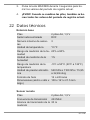
22 Technical data
Base station
Batteries 2x AA, 1.5 V
Radio controlled signal DCF
Maximum number of sensors 3
Temperature unit °C/°F
Humidity measuring range 20% to 90%
Humidity resolution 1%
Temperature measuring
range
-5°C to 50°C (23°F to 122°F)
Seite wird geladen ...
Seite wird geladen ...
Seite wird geladen ...
Seite wird geladen ...
Seite wird geladen ...
Seite wird geladen ...
Seite wird geladen ...
Seite wird geladen ...
Seite wird geladen ...
Seite wird geladen ...
Seite wird geladen ...
Seite wird geladen ...
Seite wird geladen ...
Seite wird geladen ...
Seite wird geladen ...
Seite wird geladen ...
Seite wird geladen ...
Seite wird geladen ...
Seite wird geladen ...
Seite wird geladen ...
Seite wird geladen ...
Seite wird geladen ...
Seite wird geladen ...
Seite wird geladen ...
Seite wird geladen ...
Seite wird geladen ...
Seite wird geladen ...
Seite wird geladen ...
Seite wird geladen ...
Seite wird geladen ...
Seite wird geladen ...
Seite wird geladen ...
Seite wird geladen ...
Seite wird geladen ...
Seite wird geladen ...
Seite wird geladen ...
Seite wird geladen ...
Seite wird geladen ...
Seite wird geladen ...
Seite wird geladen ...
Seite wird geladen ...
Seite wird geladen ...
Seite wird geladen ...
Seite wird geladen ...
Seite wird geladen ...
Seite wird geladen ...
Seite wird geladen ...
Seite wird geladen ...
Seite wird geladen ...
Seite wird geladen ...
Seite wird geladen ...
Seite wird geladen ...
Seite wird geladen ...
Seite wird geladen ...
Seite wird geladen ...
Seite wird geladen ...
Seite wird geladen ...
Seite wird geladen ...
Seite wird geladen ...
Seite wird geladen ...
Seite wird geladen ...
Seite wird geladen ...
Seite wird geladen ...
Seite wird geladen ...
Seite wird geladen ...
Seite wird geladen ...
Seite wird geladen ...
Seite wird geladen ...
Seite wird geladen ...
Seite wird geladen ...
Seite wird geladen ...
Seite wird geladen ...
Seite wird geladen ...
Seite wird geladen ...
Seite wird geladen ...
Seite wird geladen ...
Seite wird geladen ...
Seite wird geladen ...
Seite wird geladen ...
Seite wird geladen ...
Seite wird geladen ...
Seite wird geladen ...
Seite wird geladen ...
Seite wird geladen ...
Seite wird geladen ...
Seite wird geladen ...
Seite wird geladen ...
Seite wird geladen ...
-
 1
1
-
 2
2
-
 3
3
-
 4
4
-
 5
5
-
 6
6
-
 7
7
-
 8
8
-
 9
9
-
 10
10
-
 11
11
-
 12
12
-
 13
13
-
 14
14
-
 15
15
-
 16
16
-
 17
17
-
 18
18
-
 19
19
-
 20
20
-
 21
21
-
 22
22
-
 23
23
-
 24
24
-
 25
25
-
 26
26
-
 27
27
-
 28
28
-
 29
29
-
 30
30
-
 31
31
-
 32
32
-
 33
33
-
 34
34
-
 35
35
-
 36
36
-
 37
37
-
 38
38
-
 39
39
-
 40
40
-
 41
41
-
 42
42
-
 43
43
-
 44
44
-
 45
45
-
 46
46
-
 47
47
-
 48
48
-
 49
49
-
 50
50
-
 51
51
-
 52
52
-
 53
53
-
 54
54
-
 55
55
-
 56
56
-
 57
57
-
 58
58
-
 59
59
-
 60
60
-
 61
61
-
 62
62
-
 63
63
-
 64
64
-
 65
65
-
 66
66
-
 67
67
-
 68
68
-
 69
69
-
 70
70
-
 71
71
-
 72
72
-
 73
73
-
 74
74
-
 75
75
-
 76
76
-
 77
77
-
 78
78
-
 79
79
-
 80
80
-
 81
81
-
 82
82
-
 83
83
-
 84
84
-
 85
85
-
 86
86
-
 87
87
-
 88
88
-
 89
89
-
 90
90
-
 91
91
-
 92
92
-
 93
93
-
 94
94
-
 95
95
-
 96
96
-
 97
97
-
 98
98
-
 99
99
-
 100
100
-
 101
101
-
 102
102
-
 103
103
-
 104
104
-
 105
105
-
 106
106
-
 107
107
-
 108
108


Bresser 7060200 Bedienungsanleitung
- Kategorie
- Wetterstationen
- Typ
- Bedienungsanleitung
- Dieses Handbuch eignet sich auch für
in anderen Sprachen
- English: Bresser 7060200 Owner's manual
- français: Bresser 7060200 Le manuel du propriétaire
- español: Bresser 7060200 El manual del propietario
- Nederlands: Bresser 7060200 de handleiding
Verwandte Artikel
-
Bresser Tendence WSX Weather Station Bedienungsanleitung
-
-
-
Bresser TemeoTrend FSX Weather Station Bedienungsanleitung
-
-
-
-
Bresser 7007510 Bedienungsanleitung
-
-
Bresser 7000025000000 Bedienungsanleitung
Andere Dokumente
-
Celestron HomeCast 47021 Benutzerhandbuch
-
Terraillon EQUINOXE Bedienungsanleitung
-
-
EDENWOOD STATION METEO WS COLOR + CAPTEU Bedienungsanleitung
-
Hama EWS900 - 76046 Bedienungsanleitung
-
-
Ansen Electronics L5CW044TX-0 Benutzerhandbuch
-
Livoo SL261 Weather Station Benutzerhandbuch
-
Alecto WS-1850 Benutzerhandbuch
-
 as-Schwabe 24103 Operating Instructions Manual
