Victron energy Skylla-IP65 Bedienungsanleitung
- Typ
- Bedienungsanleitung

Manual
EN
Handleiding
NL
Manu
el
FR
Anleitung
DE
Manual
ES
Manuale
IT
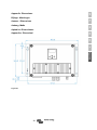
Appendix
Skylla-IP65
12/70 (1+1) & 12/70 (3)
24/35 (1+1) & 24/35 (3)

2

3
EN NL FR DE ES IT Appendix
1. SAFETY INSTRUCTIONS
1.1. General
● Please read the documentation supplied with this product first, so that you are familiar with the safety signs and directions before
using the product.
● This product is designed and tested in accordance with international standards. The equipment should be used for the
designated application only.
● WARNING: danger of electric shock
The product is used in combination with a permanent energy source (battery). Even if the equipment is switched off, a dangerous
electrical voltage may still be present at the input and/or output terminals. Always disconnect the AC power and the battery before
performing maintenance.
● The product contains no internal user-serviceable parts. Do not remove the front panel unless the mains and the battery are
disconnected. Do not put the product into operation unless all panels are fitted. All maintenance should be performed by qualified
personnel.
● Never use the product at sites where gas or dust explosions could occur. Refer to the specifications provided by the manufacturer
of the battery to ensure that the battery is suitable for use with this product. The battery manufacturer's safety instructions should
always be observed.
● WARNING: do not lift heavy objects unassisted.
1.2. Installation
● Read the installation instructions before commencing installation activities.
● This product is a safety class I device (supplied with a ground terminal for safety purposes). Its AC input and/or output
terminals must be provided with uninterruptible grounding for safety purposes. An additional grounding point is located
on the outside of the product. If it can be assumed that the grounding protection is damaged, the product should be taken out
of operation and prevented from accidentally being put into operation again; contact qualified maintenance personnel.
● Ensure that the connection cables are provided with fuses and circuit breakers. Never replace a protective device by a
component of a different type. Refer to the manual for the correct part.
● Check before switching the device on whether the available voltage source conforms to the configuration settings of the product
as described in the manual.
● Ensure that the equipment is used under the correct operating conditions. Never operate it in a wet or dusty environment.
● Ensure that there is always sufficient free space around the product for ventilation, and that ventilation openings are not blocked.
● Install the product in a heatproof environment. Ensure therefore that there are no chemicals, plastic parts, curtains or other
textiles, etc. in the immediate vicinity of the equipment.
1.3. Transport and storage
● During storage or transport of the product, ensure that the mains supply and battery cables are disconnected.
● No liability can be accepted for damage in transit if the equipment is not transported in its original packaging.
● Store the product in a dry environment; the storage temperature should range from –20°C to 60°C.
● Refer to the battery manufacturer's manual for information on transport, storage, charging, recharging and disposal of the
battery.

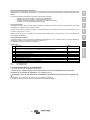
4
2. INSTALLATION AND WIRING
2.1. Installation
Find a dry and well-ventilated area to mount the Skylla-IP65 charger and battery. Keep the cable length between the charger and the
battery less than 6 meters.
The charger may be wall or floor mounted. Always make sure that air may flow freely at the back side of the cabinet. This will improve
cooling of the charger and prolong lifetime.
Wall mounting
The unit can best be mounted vertical to a wall. See appendix for exact positions of the mounting holes.
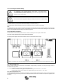
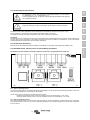
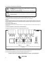
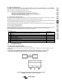
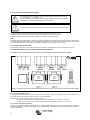
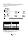
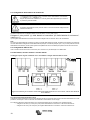
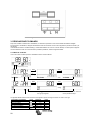
Wiring
The inlets for the mains cable, the battery cables, the remote functions and the connection to attach the earth cable are located at the
bottom of the housing; see markings on the front panel.
6 mm bolt on left hand side mounting Earth point
Grey terminal block External Voltage sense
External Temperature sense
Remote shut down
User relay
Starter battery
VE.Can cables
Black cable glands: 2 or 4 pcs Main battery cables
Black cable gland single Mains cable
Warning: For best protection against water and dust from entering the case, all openings in the grey terminal block should be
closed, either with a suitable cable or, when no connection is used, a dummy piece of cable.
Connecting earth
Connect the earth point to the installation earth. Connections to earth have to be according to applicable safety standards.
- On a ship: connect to the earth plate or to the hull of the ship.
- On land: connect to the earth of the mains. The connection to the earth of the mains has to be according to applicable
safety standards.
- Mobile applications (a vehicle, a car or a caravan): Connect to the frame of the vehicle.
The battery connections of the charger are fully floating with respect to this grounding point.
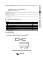
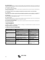
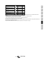
2.2. Connecting the main battery
Before the main battery is connected to the charger, make sure the charger is set to the correct battery type.
Minimum cable cross section between main battery and charger:
Skylla-IP65 type
cable length up to 1.5 m
cable length 1.5 m – 6 m
12/70 10 mm
2
16 mm
2
24/35
6 mm
2
10 mm
2
The largest possible cable lug that will fit through the battery cable glands is size S6-16. That cable lug will suit a maximum cable
diameter of 16 mm
2
and fit on an M6 bolt.

5
EN NL FR DE ES IT Appendix
2.2.1. Main battery connection sequence
1. Disconnect the mains supply.
2. Disconnect battery cables from the battery.
3. Remove the grey cover in the front panel of the charger, enabling access to the terminals.
4. Connect battery cables to the charger: plus (red) to “+BAT1”;
minus (black) to “-BAT”.
5. Connect battery cables to the battery: plus (red) to positive pole,
minus (black) to negative pole.
6. Connect the mains supply.
2.2.2 Main battery disconnection sequence
1. Disconnect the mains supply.
2. Disconnect battery cables from the battery.
3. Remove the grey cover in the front panel of the charger, enabling access to the terminals.
4. Disconnect the battery-cables from the charger.
5. Disconnect all other cables like temperature sensor and/or voltage sensor used with this particular battery.
The Skylla-IP65 is NOT protected against reverse polarity of the main battery.
("+" connected to "-" and "-" connected to "+").
Follow the installation procedure. The warranty expires when the Skylla-IP65
becomes
defective due to reverse polarity.
Disconnect the mains supply before making or breaking connections to the main battery.
When disconnecting the battery cables, be very careful not to accidentally short circuit the
battery.

6
2.3. Connecting the starter battery
The starter battery has to be connected using wire of at least 1.5 mm
2
(max. 6 mm
2
).
Connect the positive (+) battery-pole to the "Starter battery plus" connector, see Figure 1.
The negative pole of the starter battery has to be connected to the “-BAT” connection of the charger.
Note:
The starter battery can draw current from the battery connected to the main battery terminals in case the voltage of the starter battery
is lower than the voltage main battery. However, the main battery cannot draw current from the starter battery even when the starter
battery is fully charged and the main battery is at minimum charge level.
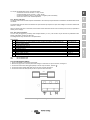
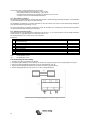
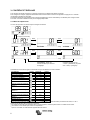
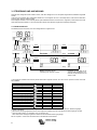
2.4. VE.Can bus connection
The two VE.Can bus connectors provide access for control with the Skylla-i control panel or NMEA 2000.
2.5. User relay, external sense and remote shut down
The wiring of these signals must be done with the mains disconnected from the charger.
Figure 1 Connectors for external voltage/temperature sensing, Rem. Shut down, VE.Can bus and Starter battery
2.5.1. External voltage sense
External voltage sensing may be used when accurate battery voltage sensing is important, such as high charging currents in
combination with long cables.
To connect the external voltage sensing option, proceed as follows:
- connect a red wire (0.75 mm
2
) between the positive battery pole and connector "+ Volt. sense"
- connect a black wire (0.75 mm
2
) between the negative battery pole and connector "- Volt. sense”
2.5.2. External temperature sense
The external temperature sensor, supplied with the charger, can be connected to these terminals in order to perform temperature
compensated charging of the battery. The sensor is electrically isolated and must be connected to the positive or negative pole of
the battery.
The Skylla-IP65 is NOT protected against reverse polarity of the starter battery.
("+" connected to "-" and "-" connected to "+").
Follow the installation procedure. The warranty expires when the Skylla-IP65
becomes
defective due to reverse polarity.
Disconnect the mains supply before making or breaking connections to the starter battery.

7
EN NL FR DE ES IT Appendix
To connect the temperature sensor, proceed as follows:
- connect the red wire to connector "+ Temp. sense"
- connect the black wire to connector "- Temp. sense"
- mount the temperature sensor on the positive or negative pole of the battery
- check in the menu for the actual temperature
2.5.3. Remote shut down
The wiring of the remote shut down requires extra attention. Since this input is quite sensitive it is advised to use twisted wires for this
connection.
The remote shut down can also be connected to an open collector opto coupler: the open circuit voltage is 5 V and the closed circuit
current is < 100 µA.
When no remote shut down is connected, the remote shut down terminals must be short circuited by a short wire (as provided on
delivery of the charger).
2.5.4. User relay connections
The user relay is triggered by a battery under-voltage situation (<11.8 V). The function may be used for any desirable action:
starting a generator, sounding an alarm etc.
The ratings of the relay can be found in the specification.
Relay modes
#
Description
Setup Menu #
0
Skylla-i behaviour: on when charging (no error condition) and battery voltage between low
and high voltage settings
12,13,14 and 15
1
Always off
2
Temperature high (>85 ⁰C)
3
Battery voltage too low
12 and 13
4
Equalization active
5
Error condition present
6
Temperate low (<-20 ⁰C)
7
Battery voltage too high
14 and 15
8
Charger in float or storage
ON : CM connected to NO
OFF : CM connected to NC
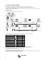
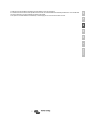
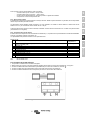
2.6. Connecting the mains
1. Check if the battery is connected to the charger.
2. Remove the grey cover in the front panel of the charger, to access the AC input connector, see Figure 2.
3. Connect the mains earth cable (green/yellow) to the AC input connector, terminal .
4. Connect the mains neutral cable (blue) to the AC input connector terminal N.
5. Connect the mains line cable (brown) to the AC input connector terminal L.
Figure 2 Mains input terminal

8
3. CONTROL AND ADJUSTMENT
When the charger is installed correctly, the charger should be set up to suit the battery connected.
To set up the charger, apply mains power and enter the setup menu by pressing “SETUP” for three seconds.
The charger will enter a standby mode (no power applied to the battery terminals) and the user can set up the unit accordingly.
See the next table for all possible adjustments.
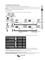
3.1. Monitor menu
The monitor menu is visible when power is applied to the charger.
Setup (3 seconds)
select
setup
select
setup
- +
select
select
setup
- +
Blinking: Use the up/down keys to
adjust.
Confirm by pressing select and exit
with setup.
The following table shows the consecutive lines when scrolling through the menu with the up/down keys:
Displayed info
Icons
Segments
Units
Battery voltage / current
.
A
Battery voltage
.
V
Battery charge current
.
A
Battery temperature
*1
.,,
°C/°F
Mains current
.
A
Battery voltage out 1
*2
.
V
Battery charge current out 1
*2
.
A
Battery voltage out 2
*2
.
V
Battery charge current out 2
*2
.
A
Battery voltage out 3
*2
.
V
Battery charge current out 3
*2
.
A
Warning message
*3 *4
Error message
*3 *4
BMS operation
*3
*1
A valid temperature is shown. “ --- “ means no sensor information or “Err” means invalid sensor data.
*2
The output channel number is shown in the first segment; only visible in a three output model.
*3
These items are only visible when relevant.
*4
After a short delay a scrolling text is shown with the error description.
With the up/down keys the user can scroll through the monitor menu.
Holding either up or down for three seconds will start the auto scrolling mode: all Monitor menu items will be shown for 5 seconds.
The auto scroll mode can be exit by pressing up or down once.

9
EN NL FR DE ES IT Appendix
3.2. Setup menu
The setup menu can be entered by pressing “SETUP” during three seconds.
Scrolling text
Icons
Segments
Units
Function or parameter
,
On/off switch
.-.
A
Maximum charge current
V
System voltage (read-only)
,-
Type
Charge algorithm
.-.-.
V
Absorption voltage
.-.-.
V
Float voltage
.
-.-
.
V
Storage voltage
.-.-.
V
Equalization voltage
,
Automatic equalization
,
Manual equalization
. -
Relay function
.-.-.
V
Low battery voltage alarm set
.-.-.
V
Low battery voltage alarm clear
.-.-.
V
High battery voltage alarm set
.
-.-
.
V
High battery voltage alarm
clear
-
Relay minimum closed time
(minutes)
.
-.-
.
°C mV
Battery temperature
compensation per cell
,
h
Bulk time protection
.-.-.
h
Absorption time
,
Storage mode
.-.-.
h
Maximum float time
.-.-.
h
Repeated absorption time
.-.-.
Day
Repeated absorption interval
.
-.
A
Low temperature charge
current
,
Watch function (start-up in
storage if battery voltage >13 V
,
BMS Present
.
-.-
.
V
Power supply voltage
.
-.
A
Input current limit
--
The intensity of the backlight
,
,
Backlight automatic turn off
after 60s
--
Text scroll speed
,
Buzzer
-
VE.Can device instance
.
Software version
System reset to default
settings
History data reset
,
Lock settings
,
Temperature unit °C/°F
After entering the setup menu, the user can scroll through the menu with the up/down keys.
With select a menu item is entered and the present value is shown. With the up/down keys the user can scroll through the available
modes or increase/decrease the value.
By pressing select again the value/item is set.
Pressing setup shortly will return to the setup menu.
When setup is completed, exit the menu by pressing “SETUP” again three seconds.

10
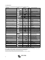
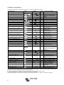
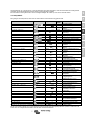
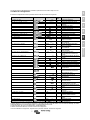
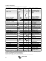
3.3. Battery selection
The charge algorithm of the charger must fit the battery type connected to the charger. The following table shows all the predefined
battery types available in the charge algorithm selection menu.
#
Description
Unit
type
Absorption
Float
Storage
Equalization
dV/dT
V
V
V
Max V @% of Inom
mV/°C
1
Gel Victron long life (OPzV)
Gel exide A600 (OPzV)
Gel MK
12 V 14.1 13.8 13.2 15.9 @ 6 % max 1hr -16
24 V 28.2 27.6 26.4 31.8 @ 6 % max 1hr -32
2
Default setting
Gel Victron deep discharge, Gel Exide A200
AGM Victron deep discharge
Stationary tubular plate (OPzS)
Rolls Marine (flooded), Rolls Solar (flooded)
12 V 14.4 13.8 13.2 15.9 @ 6 % max 1hr -16
24 V 18.8 27.6 26.4 31.8 @ 6 % max 1hr -32
3
AGM spiral cell
Rolls AGM
12 V
14.7
13.8
13.2
15.9 @ 6 % max 1hr
-16
24 V
29.4
27.6
26.4
31.8 @ 6 % max 1hr
-32
4
PzS tubular plate traction batteries or
OPzS batteries in cyclic mode 1
12 V
14.1
13.8
13.2
15.9 @ 6 % max 4hrs
-16
24 V
28.2
27.6
26.4
31.8 @ 6 % max 4hrs
-32
5
PzS tubular plate traction batteries or
OPzS batteries in cyclic mode 2
12 V
14.4
13.8
13.2
15.9 @ 6 % max 4hrs
-16
24 V
18.8
27.6
26.4
31.8 @ 6 % max 4hrs
-32
6
PzS tubular plate traction batteries or
OPzS batteries in cyclic mode 3
12 V
15
13.8
13.2
15.9 @ 6 % max 4hrs
-16
24 V
30
27.6
26.4
31.8 @ 6 % max 4hrs
-32
7
Lithium Iron Phosphate (LiFePo
4
) batteries
12 V
14.2
n.a.
13.50
n.a.
0
24 V
28.4
n.a.
26.7
n.a.
0
8
Adjustable: maximum charge current and
absorption, float, storage and equalization
voltages can be changed in the setup menu
12 V Adj. Adj. Adj.
Adj. @ 6 %
max 4hrs
Adj.
24 V Adj. Adj. Adj.
Adj. @ 6 %
max 4hrs
Adj.
9
Power supply mode
12 V
12.0
n.a.
n.a.
n.a.
0
24 V
24.0
n.a.
n.a.
n.a.
0
3.4. Power supply mode
The charger can be set to operate as a DC power supply.
In this mode, the charger functions as a constant voltage source:
1. an adjustable output voltage of 8.0 to 15.9 V (12 V type) resp. 16.0 to 31.8 Volt (24 V type)
2. a maximum output current of 60A (12 V type) resp. 30A (24 V type).
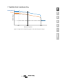
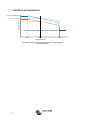
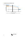
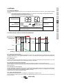
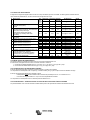
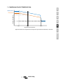
3.5. Temperature compensation (dV/dT)
The temperature sensor should be connected to the plus or negative pole of the battery.
The temperature compensation is a fixed setting, see table and fig. 4, and applies to all charge states.
The temperature sensor must be installed when:
- ambient temperature of the battery is expected to regularly be lower than 15 °C or to regularly exceed 30 °C
- charge current exceeds 15 A per 100 Ah battery capacity
Temperature compensation is not required for Li-Ion batteries.
3.6. Power Control – maximum use of limited shore current
A maximum mains current can be set in order to avoid interruption of an external fuse in the mains supply.

11
EN NL FR DE ES IT Appendix
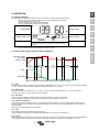
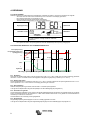
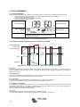
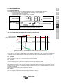
4. OPERATION
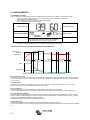
4.1. Battery charging
After applying mains power and remote shut down is not active, the display will show the following:
- All icons of the screen will be visible to check the correct functioning of the display.
- The back lighting of the display is ON.
- Next the firmware version number will be displayed.
- Finally, the actual state is displayed on the screen:
Output Voltage
Charge current
Battery charger mode State of charge
When the mains plug is blinking, the mains voltage is below
normal and the charger is reducing the maximum charge
current.
- By using Voltage sensing, the actual battery voltage is shown.
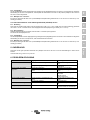
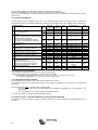
4.2. Seven stage charge curve for lead-acid batteries
4.2.1. Bulk
Entered when the charger is started or when the battery voltage falls below 13.2 V / 26.4 V (due to a heavy load) during at least
1 minute. Constant current is applied until gassing voltage is reached (14.4 V / 18.8 V).
4.2.2. Battery Safe
If absorption voltage is set higher than 14.4 V / 18.8 V, the rate of voltage increase beyond 14.4 V / 18.8 V is limited to
7mV/14mV per minute, in order to prevent excessive gassing.
4.2.3. Absorption
After the absorption voltage has been reached, the charger operates in constant voltage mode.
In case of adaptive charging, the absorption time is dependent on the bulk time, see section 3.2.
4.2.4. Automatic equalization
If automatic equalization has been set to ‘on’, the absorption period is followed by a second voltage limited constant current
period: see section 3.3. This feature will charge VRLA batteries to the full 100 %, and prevent stratification of the electrolyte in
flooded batteries.
Alternatively, manual equalization can be applied.
4.2.5. Float
Float voltage is applied to keep the battery fully charged.
In case of adaptive charging, the float voltage time is dependent on the bulk time, see section 3.2.
4.2.6. Storage
After float charge the output voltage is reduced to storage level. This level is not sufficient to compensate for slow self-discharge
of the battery, but will limit water loss and corrosion of the positive plates to a minimum when the battery is not used.
time
storage voltage
float voltage
absorption voltage
U
bulk
absorption
float
storage
100%
I
Equalization
Figure 3 Voltage and current during different states in battery charging

12
4.2.7. Weekly battery ‘refresh’
Once a week the charger will enter Repeated Absorption-mode during one hour to ’refresh’ (i. e. to fully charge) the battery.
4.3. Four stage charge curve for Lithium Iron Phosphate (LiFePo4) batteries
4.3.1. Bulk
Entered when the charger is started, or when the battery voltage falls below 13,5 V / 27,0 V (due to a heavy load) during at least
1 minute. Constant current is applied until absorption voltage is reached (14.2 V / 28.4 V).
4.3.2. Absorption
After the absorption voltage has been reached, the charger operates in constant voltage mode.
The recommended absorption time is 2 hours.
4.3.3. Storage
After absorption charge the output voltage is reduced to storage level. This level is not sufficient to compensate for slow self-
discharge of the battery, but will maximize service life.
4.3.4. Weekly battery ‘refresh’
Once a week the charger will enter Repeated Absorption-mode during one hour to ’refresh’ (i. e. to fully charge) the battery.
5. MAINTENANCE
This charger does not require any specific maintenance. However an annual check of the battery and mains connections is
recommended.
Keep the charger dry, clean and free of dust.
6. TROUBLESHOOTING
Problem Possible cause Solution
Charger does not function
The mains is not ok
Measure mains: 120 - 240 VAC
Input or output fuses are defective
Return product to your dealer
The battery is not fully charged
A bad battery connection
Check battery connection
The wrong battery type has been selected in
the menu.
Select correct battery type in the
menu.
Cable losses too high
Use cables with larger cross
section
Use external voltage sensing
The battery is being overcharged
The wrong battery type has been selected in
the menu.
Select correct battery type in the
menu.
A battery cell is defective
Replace battery
Battery temperature too high
Overcharging or too fast charging
Connect external temperature
sensor
Error in display
See section 9
Check all charging equipment
Check cables and connections

13
EN NL FR DE ES IT Appendix
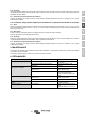
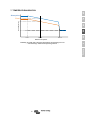
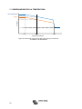
7. TEMPERATURE COMPENSATION
Float
Absorption
Battery voltage
Battery temperature
25°C
50°C
6°C
Figure 4 Temperature compensation graph for float and absorption voltages

14
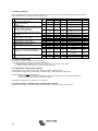
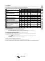
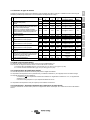
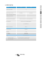
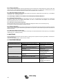
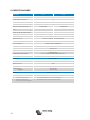
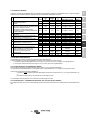
8. SPECIFICATION
Skylla-IP65 12/70 24/35
Input voltage (VAC) 120 – 240
Input voltage range (VAC)
(1)
90 – 265
Maximum AC input current 12
Frequency (Hz) 45-65
Power factor 0,98
Charge voltage 'absorption' (VDC)
(2)
See table See table
Charge voltage 'float' (VDC)
(2)
See table See table
Charge voltage ‘storage’ (VDC)
(2)
See table See table
Charge current main batt. (A)
(3)
70 35
Charge current starter batt. (A)
(4)
3 4
Charge curve, lead-acid 7 stage adaptive
Recommended battery capacity (Ah) 350-700 150-350
Charge curve, Li-Ion 2 stage, with on-off control or VE.Can bus control
Temperature sensor Yes
Power supply function Yes
Remote on-off port Yes (can be connected to a Li-Ion BMS)
CAN bus communication port Two RJ45 connectors, NMEA2000 protocol
Remote alarm relay DPST AC rating: 240 VAC/4 A DC rating: 4 A up to 35 VDC, 1 A up to 60 VDC
Forced cooling Yes
Protection Battery reverse polarity (fuse) Output short circuit Over temperature
Operating temp. range -20 to 60 °C (full output current up to 40 °C)
Humidity (non-condensing) max 95 %
ENCLOSURE
Material & Colour steel; blue, RAL 5012
Battery-connection M6 bolts
Mains connection screw-clamp 6 mm² (AWG 10)
Protection category IP65
Weight kg (lbs) 6 (14)
Dimensions hxwxd incl. glands in mm
in inches
401 x 375 x 265
(16 x 15 x 10.5)
STANDARDS
Safety EN 60335-1, EN 60335-2-29
Emission EN 55014-1, EN 61000-6-3, EN 61000-3-2
Immunity EN 55014-2, EN 61000-6-1, EN 61000-6-2, EN 61000-3-3
1) Output current will gradually reduce below
110 V to 50 % @ 100 V.
2) Depending upon battery type as selected
in the setup menu.
3) Maximum current up to 40 °C (100 °F) ambient.
Output current will reduce to 60 % at 50 °C, and to 40 % at 60 °C.
4) Depending upon state of charge of starter battery.

15
EN NL FR DE ES IT Appendix
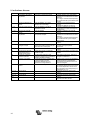
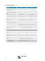
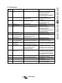
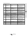
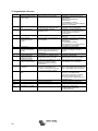
9. Error indication
Error nr
Description
Possible cause
Solution
1
battery temperature too
high
Overcharging or fast charging
Check air flow near the battery
Improve cooling of environment.
The charger stops automatically and
will resume once the battery has
cooled down.
2
battery voltage too high
Wiring mistake, or another charger is
over charging
Check all charging equipment.
Check cables and connections.
3, 4, 5
temp. sense error
Wiring mistake or temperature sensor
broken
Check the temperature sensor wiring
and if that doesn’t help replace the
temperature sensor.
6, 7, 8, 9
voltage sense error
Wiring mistake
Check the voltage sensor wiring.
17
charger temperature too
high
The heat generated by the charger
cannot be removed
Check air flow of the cabinet
Improve cooling of environment
The charger stops automatically and
will resume once the charger has
cooled down.
18
Internal error
Contact Victron service.
20
charger bulk time expired
After 10 hours of bulk charging, the
battery voltage has still not reached the
absorption voltage
Possible cell failure or higher charge
current needed.
34
Internal error
Contact Victron service.
37
No input voltage (only for
the three output version)
Mains removed or ac-input fuse blown
Check mains availability and fuse.
65
charger disappeared
during operation
One of the other chargers with which
this charger was synchronizing has
disappeared during operation
To clear the error, switch the charger
off and back on.
66
Incompatible device
The charger is being paralleled to
another charger that has different
settings and/or a different charge
algorithm
Make sure all settings are the same
and update firmware on all chargers to
the latest version.
67
BMS connection lost
Connection to the BMS lost.
Check the VE.Can bus cabling. When
the charger needs to operate in stand-
alone mode again, go to the setup
menu #31 (BMS Present) and set to N.
113, 114
Internal error
Contact Victron service.
115
Communication error
Check wiring and terminators.
116, 117,
118
Internal error
Contact Victron service.
119
Settings invalid
Restore defaults in the setup menu
#62.


1
EN NL FR DE ES IT Bijlage
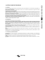
1. VEILIGHEIDSAANWIJZINGEN
1.1. Algemeen
● Lees eerst de bij dit product geleverde documentatie, zodat u bekend bent met de veiligheidsaanduidingen en -aanwijzingen
voordat u het product in gebruik neemt.
● Dit product is ontworpen en getest conform de internationale normen. De apparatuur mag enkel worden gebruikt voor de
bedoelde toepassing.
● WAARSCHUWING: kans op elektrische schok
Het product wordt gebruikt in combinatie met een permanente energiebron (accu). Zelfs als de apparatuur is uitgeschakeld, kan
er nog steeds een gevaarlijke elektrische spanning aanwezig zijn bij de ingangs- en of uitgangsklemmen. Schakel altijd de
wisselspanningsvoeding uit en ontkoppel de accu voordat u onderhoudswerkzaamheden uitvoert.
● Het product bevat geen interne onderdelen die door de gebruiker kunnen worden onderhouden. Verwijder het voorpaneel enkel
als de netstroom en de accu zijn losgekoppeld. Stel het product enkel in bedrijf als alle panelen zijn geplaatst. Alle
onderhoudswerkzaamheden dienen door gekwalificeerd personeel te worden uitgevoerd.
● Gebruik het product nooit op plaatsen waar zich gas- of stofexplosies kunnen voordoen. Raadpleeg de specificaties van de
accufabrikant om te waarborgen dat de accu geschikt is voor gebruik met dit product. Neem altijd de veiligheidsvoorschriften van
de accufabrikant in acht.
● WAARSCHUWING: til geen zware voorwerpen zonder hulp.
1.2. Installatie
● Lees de installatieaanwijzingen voordat u met de installatie begint.
● Dit is een product uit veiligheidsklasse I (dat wordt geleverd met een aardingsklem ter beveiliging). De in- en/of
uitgangsklemmen van de wisselstroom moeten zijn voorzien van een on-onderbreekbare aarding ter beveiliging. Aan de
buitenkant van het product bevindt zich een extra aardpunt. Als u vermoedt dat de aardbeveiliging is beschadigd, moet het
product buiten bedrijf worden gesteld en worden beveiligd tegen per ongeluk opnieuw inschakelen; neem hiervoor contact op met
gekwalificeerd onderhoudspersoneel.
● Zorg ervoor dat de aansluitkabels zijn voorzien van zekeringen en stroomonderbrekers. Vervang nooit een beveiliging door een
ander type component. Raadpleeg de handleiding voor het juiste onderdeel.
● Controleer voordat u het apparaat inschakelt of de beschikbare spanningsbron overeenkomt met de configuratie-instellingen
van het product, zoals beschreven in de handleiding.
● Zorg ervoor dat de apparatuur wordt gebruikt onder de juiste bedrijfsomstandigheden. Gebruik het product nooit in een vochtige
of stoffige omgeving.
● Zorg ervoor dat er rondom het product steeds voldoende vrije ruimte is voor ventilatie en dat de ventilatieopeningen niet
geblokkeerd zijn.
● Installeer het product in een hittebestendige omgeving. Zorg er daarom voor dat zich geen chemische stoffen,
kunststofonderdelen, gordijnen of andere soorten textiel enz. in de onmiddellijke omgeving van de apparatuur bevinden.
1.3. Vervoer en opslag
● Zorg er tijdens de opslag of het transport van het product voor dat de netstroom- en accukabels zijn losgekoppeld.
● Er kan geen aansprakelijkheid worden aanvaard voor transportschade als de apparatuur wordt vervoerd in een andere dan de
originele verpakking.
● Sla het product op in een droge omgeving; de opslagtemperatuur dient te liggen tussen -20°C en 60°C.
● Raadpleeg de handleiding van de accufabrikant voor informatie over transport, opslag, opladen, herladen en afvalverwijdering van
de accu.
2. INSTALLATIE EN BEDRADING
2.1. Installatie
Zoek een goed geventileerde ruimte voor de montage van de Skylla-IP65 lader en accu. Zorg ervoor dat de kabel tussen de lader en
de accu hoogstens 6 meter lang is.
De lader kan aan de muur of vloer worden gemonteerd. Zorg er altijd voor dat lucht vrij kan stromen aan de achterkant van de kast.
Hierdoor wordt de lader beter gekoeld en dit komt de levensduur ten goede.
Montage tegen de muur
De unit kan het beste verticaal tegen een muur worden gemonteerd. Zie de bijlage voor de precieze posities van de montagegaten.
Bedrading
De ingangen voor de voedingskabel, de accukabels, de afstandsfuncties en de verbinding om de aardkabel aan te sluiten,
bevinden zich aan de onderkant van de behuizing, zie de markeringen op het frontpaneel.
6 mm bout aan de linker montagekant Aardingspunt
Grijs klemmenblok Externe spanningssensor
Externe temperatuursensor
Uitschakeling op afstand
Gebruikersrelais
Startaccu
VE.Can-kabels

2
Zwarte kabelwartels: 2 of 4 stuks Hoofdaccu-kabels
Zwarte kabelwartel enkel Voedingskabel
Waarschuwing: Voor de beste bescherming tegen het binnendringen van water en stof in de behuizing dienen alle openingen in
het grijze klemmenblok te worden afgesloten, of met een geschikte kabel of, als er geen verbinding wordt gebruikt, een stuk
dummy-kabel.
De aarding aansluiten
Verbind het aardingspunt met de aarde van de installatie. Aardverbindingen moeten voldoen aan de van toepassing zijnde
veiligheidsnormen.
- Op een schip: aansluiting op de aardplaat of op de scheepsromp.
- Aan land: aansluiting op de aarding van de netstroom. De aansluiting op de aarding van de netstroom moet voldoen
aan de van toepassing zijde veiligheidsnormen.
- Mobiele toepassingen (een voertuig, een auto of een caravan): aansluiting op het chassis van het voertuig.
De accuverbindingen van de lader zijn volledig zwevend met betrekking tot dit aardpunt.
2.2. De hoofdbatterij aansluiten
Voordat de hoofdaccu wordt aangesloten op de lader, dient u ervoor te zorgen dat de lader is ingesteld op het juiste accutype.
Minimale kabeldoorsnede tussen hoofdaccu en lader:
Skylla-IP65 type kabellengte tot 1.5 m kabellengte 1.5 m – 6 m
12/70 10 mm
2
16 mm
2
24/35 6 mm
2
10 mm
2
De grootst mogelijke kabelschoen die door de accukabelwartels past is maat S6-16. De kabelschoen past op een maximale
kabeldiameter van 16 mm
2
en een M6-bout.
2.2.1. Aansluitvolgorde hoofdaccu
1. Koppel de voeding los.
2. Koppel de accukabels los van de accu.
3. Verwijderen de grijze afdekking in het frontpaneel van de lader, zodat de klemmen toegankelijk worden.
4. Sluit de accukabels aan op de lader: plus (rood) op “+BAT1”;
min (zwart) op “-BAT”.
5. Sluit de accukabels aan op de accu: plus (rood) op de pluspool,
min (zwart) op de minpool.
6. Sluit de voeding aan.
2.2.2 Loskoppelvolgorde hoofdaccu
1. Koppel de voeding los.
2. Koppel de accukabels los van de accu.
3. Verwijderen de grijze afdekking in het frontpaneel van de lader, zodat de klemmen toegankelijk worden.
4. Koppel de accukabels los van de lader.
5. Koppel alle overige kabels los, zoals die van de temperatuursensor en/of spanningssensor, die voor deze specifieke accu worden
gebruikt.
De Skylla-IP65 is NIET beschermd tegen omgekeerde polariteit van de hoofdaccu.
("+" aangesloten op "-" en "-" aangesloten op "+").
Volg de installatieprocedure. De garantie vervalt als de Skylla-IP65
defect raakt als gevolg
van omgekeerde polariteit.
Koppel de voeding los voordat u verbindingen naar de hoofdaccu maakt of verbreekt.
Let erop dat de accu bij het loskoppelen van de accukabels niet per ongeluk kortsluiting
maakt.

3
EN NL FR DE ES IT Bijlage
2.3. Aansluiting van de startaccu
De startaccu moet worden aangesloten met een kabel met een doorsnede van minimaal 1.5 mm
2
(max. 6 mm
2
).
Sluit de positieve (+) accupool aan op de aansluiting "Startaccu positief", zie Figure 1.
De negatieve accupool moet worden aangesloten op de “-BAT” aansluiting van de lader.
Opmerking:
De startaccu kan stroom verbruiken van de accu die is aangesloten op de hoofdaccuklemmen als de spanning van de startaccu lager
is dan de spanning van de hoofdaccu. De hoofdaccu kan echter geen stroom verbruiken van de startaccu, ook al is de startaccu
volledig opgeladen en het laadniveau van de hoofdaccu minimaal is.
2.4. VE.Can-bus aansluiting
De twee VE.Can-bus aansluitingen bieden toegang voor bediening via het Skylla-i bedieningspaneel of NMEA 2000.
2.5. Gebruikersrelais, externe sensor en uitschakeling op afstand
De bedrading van deze signalen moet worden uitgevoerd als de lader is losgekoppeld van de netstroom.
Afbeelding 5 Stekker voor externe spannings-/temperatuursensor, uitsch. op afstand, VE.Can-bus en startaccu
2.5.1. Externe spanningssensor
Een externe spanningssensor kan worden gebruikt als het belangrijk is om de accuspanning nauwkeurig te bepalen, zoals in het
geval van hoge laadstromen in combinatie met lange kabels.
Ga als volgt te werk om de externe spanningssensor aan te sluiten:
- verbind de rode draad (0,75 mm
2
) tussen de positieve accupool en de aansluiting "+ Volt. sense"
- verbind de zwarte draad (0,75 mm
2
) tussen de negatieve accupool en de aansluiting "- Volt. sense”
2.5.2. Externe temperatuursensor
De externe temperatuursensor die bij de lader wordt geleverd, kan worden aangesloten op deze klemmen voor temperatuur
gecompenseerd laden van de accu. De sensor is elektrisch geïsoleerd en moet worden aangesloten op de positieve of negatieve
pool van de accu.
De Skylla-IP65 is NIET beschermd tegen omgekeerde polariteit van de startaccu.
("+" aangesloten op "-" en "-" aangesloten op "+").
Volg de installatieprocedure. De garantie vervalt als de Skylla-IP65
defect raakt als gevolg
van omgekeerde polariteit.
Koppel de voeding los voordat u verbindingen naar de startaccu maakt of verbreekt.

4
Ga als volgt te werk om de temperatuursensor aan te sluiten:
- sluit de rode draad aan op de aansluiting "+ Temp. sense"
- sluit de zwarte draad aan op de aansluiting "- Temp. sense"
- monteer de temperatuursensor op de positieve of negatieve pool van de accu
- controleer in het menu de daadwerkelijke temperatuur
2.5.3. Uitschakeling op afstand
De bedrading van de uitschakeling op afstand vereist extra aandacht. Omdat deze ingang behoorlijk gevoelig is, wordt aanbevolen
om gevlochten aderparen te gebruiken voor deze verbinding.
De uitschakeling op afstand kan ook worden aangesloten op een open-collector opto-coupler: de open klemspanning bedraagt 5V
en de gesloten klemspanning bedraagt < 100 µA.
Als er geen uitschakeling op afstand is aangesloten, moeten de aansluiting voor uitschakeling op afstand worden kortgesloten
met een korte draad (wordt meegeleverd met de lader).
2.5.4. Gebruikersrelaisaansluitingen
Het gebruikersrelais wordt getriggerd door onderspanning van de accu (< 11,8 V). Deze functie kan voor alle nodige handelingen
worden gebruikt: een aggregaat starten, een alarm laten klinken, enz.
De vermogenswaarden van het relais vindt u in de specificatie.
Relaismodi
#
Beschrijving
Nr. set-up-menu
0
Gedrag Skylla-i: aan als opladen (geen storing) en accuspanning tussen lage en hoge
spanningsinstellingen
12, 13, 14 en 15
1
Altijd uit
2
Temperatuur hoog (>85 ⁰C)
3
Accuspanning te laag
12 en 13
4
Egalisatie actief
5
Storing opgetreden
6
Temperatuur laag (<-20 ⁰C)
7
Accuspanning te hoog
14 en 15
8
Lader in druppel- of opslaglading
AAN : CM aangesloten op NO
UIT : CM aangesloten op NC
2.6. Aansluiting van de voeding
1. Controleer of de accu is aangesloten op de lader.
2. Verwijder de grijze afdekking in het frontpaneel van de lader om toegang te krijgen tot de AC-ingangsstekker, zie Figure 2.
3. Verbind de voedings-aardkabel (groen/geel) met de AC-ingangsstekker, klem .
4. Sluit de neutrale voedingskabel (blauw) aan op klem N van de AC-ingangsaansluiting.
5. Sluit de voedingslijnkabel (bruin) aan op klem L van de AC-ingangsaansluiting.
Afbeelding 6 Ingangsaansluiting voeding
Seite wird geladen ...
Seite wird geladen ...
Seite wird geladen ...
Seite wird geladen ...
Seite wird geladen ...
Seite wird geladen ...
Seite wird geladen ...
Seite wird geladen ...
Seite wird geladen ...
Seite wird geladen ...
Seite wird geladen ...
Seite wird geladen ...
Seite wird geladen ...
Seite wird geladen ...
Seite wird geladen ...
Seite wird geladen ...
Seite wird geladen ...
Seite wird geladen ...
Seite wird geladen ...
Seite wird geladen ...
Seite wird geladen ...
Seite wird geladen ...
Seite wird geladen ...
Seite wird geladen ...
Seite wird geladen ...
Seite wird geladen ...
Seite wird geladen ...
Seite wird geladen ...
Seite wird geladen ...
Seite wird geladen ...
Seite wird geladen ...
Seite wird geladen ...
Seite wird geladen ...
Seite wird geladen ...
Seite wird geladen ...
Seite wird geladen ...
Seite wird geladen ...
Seite wird geladen ...
Seite wird geladen ...
Seite wird geladen ...
Seite wird geladen ...
Seite wird geladen ...
Seite wird geladen ...
Seite wird geladen ...
Seite wird geladen ...
Seite wird geladen ...
Seite wird geladen ...
Seite wird geladen ...
Seite wird geladen ...
Seite wird geladen ...
Seite wird geladen ...
Seite wird geladen ...
Seite wird geladen ...
Seite wird geladen ...
Seite wird geladen ...
Seite wird geladen ...
Seite wird geladen ...
Seite wird geladen ...
Seite wird geladen ...
Seite wird geladen ...
Seite wird geladen ...
Seite wird geladen ...
Seite wird geladen ...
Seite wird geladen ...
Seite wird geladen ...
Seite wird geladen ...
Seite wird geladen ...
Seite wird geladen ...
Seite wird geladen ...
-
 1
1
-
 2
2
-
 3
3
-
 4
4
-
 5
5
-
 6
6
-
 7
7
-
 8
8
-
 9
9
-
 10
10
-
 11
11
-
 12
12
-
 13
13
-
 14
14
-
 15
15
-
 16
16
-
 17
17
-
 18
18
-
 19
19
-
 20
20
-
 21
21
-
 22
22
-
 23
23
-
 24
24
-
 25
25
-
 26
26
-
 27
27
-
 28
28
-
 29
29
-
 30
30
-
 31
31
-
 32
32
-
 33
33
-
 34
34
-
 35
35
-
 36
36
-
 37
37
-
 38
38
-
 39
39
-
 40
40
-
 41
41
-
 42
42
-
 43
43
-
 44
44
-
 45
45
-
 46
46
-
 47
47
-
 48
48
-
 49
49
-
 50
50
-
 51
51
-
 52
52
-
 53
53
-
 54
54
-
 55
55
-
 56
56
-
 57
57
-
 58
58
-
 59
59
-
 60
60
-
 61
61
-
 62
62
-
 63
63
-
 64
64
-
 65
65
-
 66
66
-
 67
67
-
 68
68
-
 69
69
-
 70
70
-
 71
71
-
 72
72
-
 73
73
-
 74
74
-
 75
75
-
 76
76
-
 77
77
-
 78
78
-
 79
79
-
 80
80
-
 81
81
-
 82
82
-
 83
83
-
 84
84
-
 85
85
-
 86
86
-
 87
87
-
 88
88
-
 89
89


Victron energy Skylla-IP65 Bedienungsanleitung
- Typ
- Bedienungsanleitung
in anderen Sprachen
Verwandte Artikel
-
Victron energy Skylla-IP44 Bedienungsanleitung
-
-
-
Victron energy Skylla-i Control GX Bedienungsanleitung
-
-
-
-
-
-
Andere Dokumente
-
 Zivan BG 9 User and Installation Manual
-
Quick SBC 140 NRG FR Manual Of Installation And Use
-
Samlexpower BSWM 160 DUAL Bedienungsanleitung
-
Whisper Power MC 24/12-12 Benutzerhandbuch
-
Fourstar Group 11213769P Benutzerhandbuch
-
Telair ACB 15A 2out Benutzerhandbuch
-
-
