Yamaha PSR-8000 Benutzerhandbuch
- Kategorie
- Synthesizer
- Typ
- Benutzerhandbuch
Dieses Handbuch eignet sich auch für


92-469- ➀
ENVIRONMENTAL ISSUES: Yamaha strives to pro-
duce products that are both user safe and environmentally
friendly. We sincerely believe that our products and the
production methods used to produce them, meet these
goals. In keeping with both the letter and the spirit of the
law, we want you to be aware of the following:
Battery Notice: This product MAY contain a small non-
rechargable battery which (if applicable) is soldered in
place. The average life span of this type of battery is ap-
proximately five years. When replacement becomes nec-
essary, contact a qualified service representative to per-
form the replacement.
Warning: Do not attempt to recharge, disassemble, or
incinerate this type of battery. Keep all batteries away
from children. Dispose of used batteries promptly and as
regulated by applicable laws. Note: In some areas, the
servicer is required by law to return the defective parts.
However, you do have the option of having the servicer
dispose of these parts for you.
Disposal Notice: Should this product become damaged
beyond repair, or for some reason its useful life is consid-
ered to be at an end, please observe all local, state, and
federal regulations that relate to the disposal of products
that contain lead, batteries, plastics, etc.
NOTICE: Service charges incurred due to lack of knowl-
edge relating to how a function or effect works (when the
unit is operating as designed) are not covered by the
manufacturer’s warranty, and are therefore the owners
responsibility. Please study this manual carefully and con-
sult your dealer before requesting service.
NAME PLATE LOCATION: The graphic below indi-
cates the location of the name plate. The model number,
serial number, power requirements, etc., are located on
this plate. You should record the model number, serial
number, and the date of purchase in the spaces provided
below and retain this manual as a permanent record of
your purchase.
CAUTION
RISK OF ELECTRIC SHOCK
DO NOT OPEN
CAUTION: TO REDUCE THE RISK OF ELECTRIC SHOCK.
DO NOT REMOVE COVER (OR BACK).
NO USER-SERVICEABLE PARTS INSIDE.
REFER SERVICING TO QUALIFIED SERVICE PERSONNEL.
PRODUCT SAFETY MARKINGS: Yamaha electronic
products may have either labels similar to the graphics
shown below or molded/stamped facsimiles of these
graphics on the enclosure. The explanation of these graph-
ics appears on this page. Please observe all cautions indi-
cated on this page and those indicated in the safety in-
struction section.
The exclamation point within the equi-
lateral triangle is intended to alert the
user to the presence of important oper-
ating and maintenance (servicing) in-
structions in the literature accompany-
ing the product.
The lightning flash with arrowhead
symbol, within the equilateral triangle,
is intended to alert the user to the pres-
ence of uninsulated “dangerous volt-
age” within the product’s enclosure that
may be of sufficient magnitude to con-
stitute a risk of electrical shock.
IMPORTANT NOTICE: All Yamaha electronic prod-
ucts are tested and approved by an independent safety
testing laboratory in order that you may be sure that when
it is properly installed and used in its normal and custom-
ary manner, all foreseeable risks have been eliminated.
DO NOT modify this unit or commission others to do so
unless specifically authorized by Yamaha. Product per-
formance and/or safety standards may be diminished.
Claims filed under the expressed warranty may be denied
if the unit is/has been modified. Implied warranties may
also be affected.
SPECIFICATIONS SUBJECT TO CHANGE: The
information contained in this manual is believed to be
correct at the time of printing. However, Yamaha reserves
the right to change or modify any of the specifications
without notice or obligation to update existing units.
SPECIAL MESSAGE SECTION
Model _____________________________________
Serial No. __________________________________
Purchase Date ______________________________
CAUTION
RISK OF ELECTRIC SHOCK
DO NOT OPEN
AVIS :
RISQUE DE CHOC ÉLECTRIQUE–NE PAS OUVRIR.
WARNING :
TO REDUCE THE RISK OF FIRE OR ELECTRIC SHOCK,
DO NOT EXPOSE THIS PRODUCT TO RAIN OR MOISTURE.
TO HOST MIDI FOOT PEDAL
AC INLET
IN OUT THRU SWITCH 1 SWITCH 2 VOLUMEPC-1PC-2
MIDIMac
LOOP SEND AUX IN/LOOP RETURN AUX OUT
R L/L+R R L/L+R
MIN MAX
TRIM
L/L+RR

WARNING- When using any electrical or electronic prod-
uct, basic precautions should always be followed. These pre-
cautions include, but are not limited to, the following:
1. Read all Safety Instructions, Installation Instructions,
Special Message Section items, and any Assembly Instructions
found in this manual BEFORE making any connections, in-
cluding connection to the main supply.
2. Main Power Supply Verification: Yamaha products are
manufactured specifically for the supply voltage in the area
where they are to be sold. If you should move, or if any doubt
exists about the supply voltage in your area, please contact
your dealer for supply voltage verification and (if applicable)
instructions. The required supply voltage is printed on the
name plate. For name plate location, please refer to the graphic
found in the Special Message Section of this manual.
3. This product may be equipped with a polarized plug
(one blade wider than the other). If you are unable to insert the
plug into the outlet, turn the plug over and try again. If the
problem persists, contact an electrician to have the obsolete
outlet replaced. Do NOT defeat the safety purpose of the plug.
4. Some electronic products utilize external power sup-
plies or adapters. Do NOT connect this type of product to any
power supply or adapter other than one described in the owners
manual, on the name plate, or specifically recommended by
Yamaha.
5. WARNING: Do not place this product or any other
objects on the power cord or place it in a position where any-
one could walk on, trip over, or roll anything over power or
connecting cords of any kind. The use of an extension cord is
not recommended! If you must use an extension cord, the
minimum wire size for a 25' cord (or less) is 18 AWG. NOTE:
The smaller the AWG number, the larger the current handling
capacity. For longer extension cords, consult a local electri-
cian.
6. Ventilation: Electronic products, unless specifically
designed for enclosed installations, should be placed in loca-
tions that do not interfere with proper ventilation. If instruc-
tions for enclosed installations are not provided, it must be
assumed that unobstructed ventilation is required.
7. Temperature considerations: Electronic products
should be installed in locations that do not significantly con-
tribute to their operating temperature. Placement of this prod-
uct close to heat sources such as; radiators, heat registers and
other devices that produce heat should be avoided.
8. This product was NOT designed for use in wet/damp loca-
tions and should not be used near water or exposed to rain. Exam-
ples of wet/damp locations are; near a swimming pool, spa, tub,
sink, or wet basement.
9. This product should be used only with the components
supplied or; a cart, rack, or stand that is recommended by the
manufacturer. If a cart, rack, or stand is used, please observe all
safety markings and instructions that accompany the accessory
product.
10. The power supply cord (plug) should be disconnected from
the outlet when electronic products are to be left unused for ex-
tended periods of time. Cords should also be disconnected when
there is a high probability of lightening and/or electrical storm
activity.
11. Care should be taken that objects do not fall and liquids are
not spilled into the enclosure through any openings that may exist.
12. Electrical/electronic products should be serviced by a
qualified service person when:
a. The power supply cord has been damaged; or
b. Objects have fallen, been inserted, or liquids have been
spilled into the enclosure through openings; or
c. The product has been exposed to rain: or
d. The product dose not operate, exhibits a marked change
in performance; or
e. The product has been dropped, or the enclosure of the
product has been damaged.
13. Do not attempt to service this product beyond that de-
scribed in the user-maintenance instructions. All other servicing
should be referred to qualified service personnel.
14. This product, either alone or in combination with an ampli-
fier and headphones or speaker/s, may be capable of producing
sound levels that could cause permanent hearing loss. DO NOT
operate for a long period of time at a high volume level or at a
level that is uncomfortable. If you experience any hearing loss or
ringing in the ears, you should consult an audiologist.
IMPORTANT: The louder the sound, the shorter the time period
before damage occurs.
15. Some Yamaha products may have benches and/or acces-
sory mounting fixtures that are either supplied as a part of the
product or as optional accessories. Some of these items are de-
signed to be dealer assembled or installed. Please make sure that
benches are stable and any optional fixtures (where applicable) are
well secured BEFORE using. Benches supplied by Yamaha are
designed for seating only. No other uses are recommended.
INFORMATION RELATING TO PERSONAL INJURY, ELECTRICAL SHOCK,
AND FIRE HAZARD POSSIBILITIES HAS BEEN INCLUDED IN THIS LIST.
IMPORTANT SAFETY INSTRUCTIONS
PLEASE KEEP THIS MANUAL
92-469-2

PRECAUTIONS
PLEASE READ CAREFULLY BEFORE PROCEEDING
* Please keep these precautions in a safe place for future reference.
• Do not open the instrument or attempt to disassemble the internal parts
or modify them in any way. The instrument contains no user-serviceable
parts. If it should appear to be malfunctioning, discontinue use immedi-
ately and have it inspected by qualified Yamaha service personnel.
• Do not expose the instrument to rain, use it near water or in damp or wet
conditions, or place containers on it containing liquids which might spill
into any openings.
• If the power cord or plug becomes frayed or damaged, or if there is a
sudden loss of sound during use of the instrument, or if any unusual smells
• Do not place the power cord near heat sources such as heaters or radia-
tors, and do not excessively bend or otherwise damage the cord, place
heavy objects on it, or place it in a position where anyone could walk on,
trip over, or roll anything over it.
• When removing the electric plug from the instrument or an outlet, always
hold the plug itself and not the cord. Pulling by the cord can damage it.
• Do not connect the instrument to an electrical outlet using a multiple-
connector. Doing so can result in lower sound quality, or possibly cause
overheating in the outlet.
• Remove the electric plug from the outlet when the instrument is not to be
used for a long time, or during electrical storms.
• Before connecting the instrument to other electronic components, turn off
the power for all components. Before turning the power on or off for all
components, set all volume levels to minimum.
• Do not expose the instrument to excessive dust or vibrations, or extreme
cold or heat (such as in direct sunlight, near a heater, or in a car during the
day) to prevent the possibility of panel disfiguration or damage to the
internal components.
• Do not use the instrument near other electrical products such as televi-
sions, radios, or speakers, since this might cause interference which can
affect proper operation of the other products.
• Do not place the instrument in an unstable position where it might acci-
dentally fall over.
• Before moving the instrument, remove all connected cables.
• When cleaning the instrument, use a soft, dry cloth. Do not use paint
thinners, solvents, cleaning fluids, or chemical-impregnated wiping cloths.
Also, do not place vinyl or plastic objects on the instrument, since this
might discolor the panel or keyboard.
• Do not rest your weight on, or place heavy objects on the instrument, and
do not use excessive force on the buttons, switches or connectors.
• Use only the stand specified for the instrument. When attaching the stand
or rack, use the provided screws only. Failure to do so could cause dam-
age to the internal components or result in the instrument falling over.
• Do not place objects in front of the instrument’s air vents on the top and
rear panels, since this may prevent adequate ventilation of the internal
components, and possibly result in the instrument overheating.
Also, be careful to place the instrument on a flat, level surface to prevent
blockage of the air vents on the bottom panel.
• Do not operate the instrument for a long period of time at a high or uncom-
fortable volume level, since this can cause permanent hearing loss. If you
experience any hearing loss or ringing in the ears, consult a physician.
■REPLACING THE BACKUP BATTERY
The PSR-8000 requires four 1.5 V C size (LR14) batteries for memory backup
power. If no backup batteries are installed, the memory contents will be lost
when the instrument is unplugged from the AC mains supply. Please use
or smoke should appear to be caused by it, immediately turn off the power
switch, disconnect the electric plug from the outlet, and have the instru-
ment inspected by qualified Yamaha service personnel.
• Only use the voltage specified as correct for the instrument. The required
voltage is printed on the name plate of the instrument.
• Before cleaning the instrument, always remove the electric plug from the
outlet. Never insert or remove an electric plug with wet hands.
• Check the electric plug periodically and remove any dirt or dust which
may have accumulated on it.
CAUTION
Always follow the basic precautions listed below to avoid the possibility of physical injury to you or others, or damage to the
instrument or other property. These precautions include, but are not limited to, the following:
alkaline batteries.
1.Before changing the battery be sure to save any important data to disk
by using the SAVE TO DISK function described on page 141.
2.Turn the PSR-8000 power OFF and unplug the power cord from both the
AC wall socket and the instrument’s rear panel. Turn the instrument up-
side down and rest it on a blanket or other soft surface.
3.Open Battery Compartment Cover
Open the battery compartment cover — located on the instrument’s
bottom panel — by pressing on the two latches on the cover and pulling
outward, as shown in the illustration.
4.Remove the old batteries (if installed).
Remove the old batteries and wait at least one minute to ensure that all
data is fully cleared.
5.Insert Batteries
Insert the four batteries, being careful to follow the polarity markings on
the bottom panel.
6.Replace Cover
Replace the compartment cover, making sure that it locks firmly in place.
• Always make sure all batteries are inserted in conformity with the +/– polar-
ity markings. Failure to do so might result in overheating, fire, or battery fluid
leakage.
• Always replace all batteries at the same time. Do not use new batteries
together with old ones. Also, do not mix battery types, such as alkaline
batteries with manganese batteries, or batteries from different makers, or
different types of batteries from the same maker, since this can cause
overheating, fire, or battery fluid leakage.
• Do not dispose of batteries in fire.
• Do not attempt to recharge batteries that are not intended to be charged.
• If the instrument is not to be in use for a long time, remove the batteries
from it (after saving any important data to disk), in order to prevent pos-
sible fluid leakage from the battery.
• Keep batteries away from children.
■SAVING USER DATA
• Always save data to a floppy disk frequently, in order to help prevent the
loss of important data due to a malfunction or user operating error.
Yamaha cannot be held responsible for damage caused by improper use or modi-
fications to the instrument, or data that is lost or destroyed.
Always turn the power off when the instrument is not in use.
Make sure to discard used batteries according to local regulations.
4
(1)
WARNING
Always follow the basic precautions listed below to avoid the possibility of serious injury or even death from electrical shock,
short-circuiting, damages, fire or other hazards. These precautions include, but are not limited to, the following:

will pick up a layer of magnetic particles from the disks used that will
eventually cause read and write errors.
• To maintain the disk drive in optimum working order Yamaha recom-
mends that you use a commercially-available dry-type head cleaning
disk to clean the head about once a month. Ask your Yamaha dealer
about the availability of proper head-cleaning disks.
Never insert anything but floppy disks into the disk drive. Other objects
may cause damage to the disk drive or floppy disks.
■ About the Floppy Disks
To handle floppy disks with care:
• Do not place heavy objects on a disk or bend or apply pressure to the
disk in any way. Always keep floppy disks in their protective cases
when they are not in use.
• Do not expose the disk to direct sunlight, extremely high or low tem-
peratures, or excessive humidity, dust or liquids.
• Do not open the sliding shutter and touch the exposed surface of the
floppy disk inside.
• Do not expose the disk to magnetic fields, such as those produced by
televisions, speakers, motors, etc., since magnetic fields can partially or
completely erase data on the disk, rendering it unreadable.
• Never use a floppy disk with a deformed shutter or housing.
• Do not attach anything other than the provided labels to a floppy disk.
Also make sure that labels are attached in the proper location.
To protect your data (Write-protect Tab):
• To prevent accidental erasure of important data, slide the disk’s write-
protect tab to the “protect” position (tab open).
WARNING
• Before beginning installation, switch off the power to the PSR-8000 and
connected peripherals, and unplug them from the power outlet. Then
remove all cables connecting the PSR-8000 to other devices. (Leaving
the power cord connected while working can result in electric shock.
Leaving other cables connected can interfere with work.)
• Do not disassemble, modify, or apply excessive force to board areas and
connectors on hard disk, and SIMMs. Bending or tampering with boards
and connectors may lead to electric shock, fire, or equipment failures.
CAUTION
• Before handling the internal hard disk or SIMMs, you should briefly touch
the metal surface to which the hard-disk or SIMM cover is attached (or
Precautions
• Be sure to handle floppy disks and treat the disk drive with care. Follow
the important precautions below.
Compatible Disk Type
• 3.5” 2DD and 2HD type floppy disks can be used.
■ Inserting/Ejecting Floppy Disks
To insert a floppy disk into the disk drive:
• Hold the disk so that the label of the
disk is facing upward and the sliding
shutter is facing forward, towards
the disk slot. Carefully insert the disk
into the slot, slowly pushing it all the
way in until it clicks into place and
the eject button pops out.
To eject a floppy disk:
• Before ejecting a floppy disk make
sure that the floppy disk drive is not
in operation (the DISK IN USE indi-
cator should be off, except when the
internal hard disk is being accessed).
Press the eject button slowly as far as it will go; the disk will automati-
cally pop out. When the disk is fully ejected, carefully remove it by hand.
• Never attempt to remove the disk or turn the power off during recording,
reading and playing back. Doing so can damage the disk and possibly
the disk drive.
• If the eject button is pressed too quickly, or if it is not pressed in as far as
it will go, the disk may not eject properly. The eject button may become
stuck in a half-pressed position with the disk extending from the drive
slot by only a few millimeters. If this happens, do not attempt to pull out
the partially ejected disk, since using force in this situation can damage
the disk drive mechanism or the floppy disk. To remove a partially ejected
disk, try pressing the eject button once again, or push the disk back into
the slot and then repeat the eject procedure.
• Be sure to remove the floppy disk from the disk drive before turning off
the power. A floppy disk left in the drive for extended periods can easily
pick up dust and dirt that can cause data read and write errors.
Cleaning the Disk Drive Read/Write Head
• Clean the read/write head regularly. This instrument employs a preci-
sion magnetic read/write head which, after an extended period of use,
other such metallic area — be careful of any sharp edges) with your
bare hand so as to drain off any static charge from your body. Note that
even a slight amount of electrostatic discharge may cause damage to
these components.
• It is recommended that you wear gloves to protect your hands from
metallic projections on the PSR-8000 hard disk, SMMs, and other com-
ponents. Touching leads or connectors with bare hands may cause fin-
ger cuts, and may also result in poor electrical contact or electrostatic
damage.
• Take care to avoid dropping screws into the PSR-8000 unit. If a screw
does fall in, be sure to remove it before replacing the cover and powering
up the unit. Starting the unit with a loose screw inside may lead to im-
proper operation or equipment failure. (If you are unable to retrieve a
dropped screw, consult your Yamaha dealer for advice.)
Handling the Floppy Disk Drive(FDD) and Floppy Disk
Handling and Installation of Options
Data backup
• For maximum data security Yamaha recommends that you keep two
copies of important data on separate floppy disks. This gives you a backup
if one disk is lost or damaged. To make a backup disk use the COPY
FILE/FD function on page 143.
Write protected Write enabled
YAMAHA is not responsible for damage caused by improper handling or operation.
YAMAHA provides no guarantee against disk damage.
* If SIMM memory, or hard disk fails to work properly, consult the item’s dealer or manufacturer for advice.
* Yamaha will not be held responsible for any damage or injury resuting from improper installation.
5
This lamp is always on
while the power is on.
DISK IN USE

Congratulations!
You are the proud owner of an extraordinary electronic keyboard. The Yamaha PSR-8000
PortaTone combines the most advanced tone generation technology with state-of-the-art digital
electronics and features to give you stunning sound quality with maximum musical versatility. The
advanced Auto Accompaniment, Vocal Harmony, and Sampler features, in particular, are brilliant
examples of how Yamaha technology can significantly expand your musical horizons. A large-size
graphic display and easy-to-use interface also greatly enhance the operability of this advanced
instrument.
In order to make the most of your PortaTone’s features and vast performance potential, we urge
you to read the manuals thoroughly while trying out the various features described. Keep the manuals
in a safe place for later reference.
Packing List
Your PSR-8000 includes the following items:
• PSR-8000 PortaTone x 1
• AC Power Cord x 1
• AC Plug Adaptor x 1 (in applicable areas only)
• Music Stand x 1
• Audio CD x 1 (includes sound sources for sampling: page 88)
• Floppy Disk x 1 (includes accompaniment style files: page 28)
• Owner’s Manual
• Unauthorized copying of copyrighted software for purposes other than the purchaser’s personal use is prohib-
ited.
• The Vocal Harmony feature included in this product is manufactured under license from IVL Technologies Ltd.,
U.S. Patent numbers 5231671, 5301259, and 5428708.
● Trademarks:
• Apple and Macintosh are trademarks of Apple Computer, Inc.
• IBM-PC/AT is a trademark of International Business MachinesCorporation.
• Windows is the registered trademark of Microsoft
®
Corporation.
• All other trademarks are the property of their respective holders.
6
• The illustrations and LCD screens as shown in this owner’s manual are for instructional purposes only, and may
appear somewhat different from those on your instrument.
GM System Level 1
“GM System Level 1” is an addition to the MIDI standard which
guarantees that any data conforming to the standard will play
accurately on any GM-compatible tone generator or synthe-
sizer from any manufacturer.
XG
XG is a new Yamaha MIDI specification which significantly
expands and improves on the “GM System Level 1” standard
with greater voice handling capacity, expressive control, and
effect capability while retaining full compatibility with GM. By
using the PSR-8000’s XG voices, it is possible to record XG-
compatible song files.
XF
The Yamaha XF format enhances the SMF (Standard MIDI
File) strandard with greater functionality and open-ended
expandability for the future. The PSR-8000 is capable of
displaying lyrics when an XF file containing lyric data is
played.
• SMF (Standard MIDI File) is the most common format used for
MIDI sequence files. The PSR-8000 is compatible with SMF
Formats 0 and 1, and records “song” data using SMF Format
0.
The Panel Logos
The logos printed on the PSR-8000 panel indicate standards/formats it supports and special features it includes.

7
Main Features
Main Features
The PSR-8000 is a sophisticated electronic keyboard which offers a comprehensive range of
features for extensive musical versatility and expressive control: a touch-sensitive 61-key
keyboard, an outstanding range of voices (including XG voices), top quality auto-accompani-
ment with an extensive range of styles, song recording and playback capability, registration
memory, and a built-in floppy disk for convenient data storage and retrieval, and more.
The following features, in particular, give the PSR-8000 extraordinary musical production
and performance power.
● High-quality sampling capability — with expandable
wave memory — lets you sample and edit sounds
via microphone or from line sources, and then use
the sampled waveforms in original voices.
● Unique Vocal Harmony feature incorporates ad-
vanced voice-processing technology to automati-
cally produce vocal harmony based on a lead vocal,
making a single singer sound like a vocal group.
● An advanced effect system incorporating 8 sepa-
rate DSPs (Digital Signal Processors) and 5-band
master equalization adds depth, ambience, and
animation to your sound.
● Comprehensive Mixing Console displays provide
professional sound control and production capabil-
ity.
● Large multi-function LCD display panel with display-
based buttons and dials, plus comprehensive dis-
play prompts and messages, makes operation easy
and intuitive.
● Create original voices using the Voice Creator fea-
ture for a totally original sound.
● Style Creator feature lets you create “groove style”
variations on existing styles, or create entirely new
styles that are a perfect match for your performing
requirements.
● One Touch Setting feature automatically selects
appropriate voice, effect, and other settings for the
selected accompaniment style — all you have to do
is select a style, press the ONE TOUCH SETTING
button and play.
● Multi Pads record and play short rhythmic and me-
lodic sequences that can be used to add impact
and variety to your performances.
● Voice/Style List Customize feature lets you rear-
range the list contents for fast, efficient access in
performance situations.
● Unique “Talk” function instantly makes the settings
you need for mid-performance announcements and
interludes.
● Loop Send and Return jacks allow extra system
flexibility: connect external signal-processing equip-
ment for enhanced effect capability, or feed a mixer
for improved sound and on-stage monitoring quality.
● Optional internal hard disk provides high-volume,
high-speed data storage and retrieval.
● A selection of MIDI Templates eliminates tedious
setup procedures by providing instantly selectable
MIDI setups for a range of situations.
● To Host interface plus a range of MIDI functions for
expanded musical performance (General MIDI Sys-
tem Level 1 and Yamaha XG/XF compatible).
DOC
The DOC voice allocation format provides data playback
compatibility with a wide range of Yamaha instruments and
MIDI devices, including the Clavinova series.
Style File Format
The Style File Format — SFF — is Yamaha’s original style file
format which uses a unique conversion system to provide
high-quality automatic accompaniment based on a wide range
of chord types. The PSR-8000 uses the SFF internally, reads
optional SFF style disks, and creates SFF styles using the
STYLE CREATOR feature.
Vocal Harmony
Vocal Harmony employs state-of-the-art digital signal process-
ing technology to automatically add appropriate vocal
harmony to a lead vocal line sung by the user. Vocal Harmony
can even change the character and gender of the lead voice
as well as the added voices to produce a wide range of vocal
harmony effects.

8
Contents
Contents
Panel Controls 10
Connections & Music Stand 12
The Demonstration 17
The PSR-8000 Display &
Display-based Controls 19
■ The MIXING CONSOLE Buttons ....19
■ The [EXIT] Button............................ 20
■ The [DIRECT ACCESS] Button ......20
■ The [LCD CONTRAST] Control ...... 20
■ The 5-language Help Function........20
■ Display Messages ........................... 21
■ Name Entry ..................................... 21
Playing the PSR-8000 22
■ Before You Begin ............................22
The PSR-8000 Parts & Voices......... 22
■ Part Poly/Mono Modes & Mono
Note Priority ....................................22
■ The XG Voices ................................ 23
■ The Organ Flute Voice ....................23
■ Keyboard Percussion and Special
Effects ............................................. 24
Procedure:
Part Selection and Voice
Assignment
..........................................24
Voice Effects........................................ 26
Other Play Mode Functions............. 26
■ Master Transpose ........................... 26
■ Octave Change ............................... 27
■ Left Hold..........................................27
■ Pitch Bend & Modulation Wheels....27
Using the Accompaniment
Section 28
Procedure:
Auto Accompaniment......... 28
■ Auto Accompaniment Fingering
Modes .............................................30
■ Auto Accompaniment Start Modes.. 33
■ The MAIN A and MAIN B Sections
and Fill-ins.......................................34
■ Tempo Control ................................35
■ Fade-ins and Fade-outs .................. 35
■ Synchronized Stop .......................... 35
■ Accompaniment Volume ................. 36
■ Accompaniment Part Switching ......36
■ Virtual Arranger ............................... 36
■ Harmony/Echo ................................37
■ One Touch Setting .......................... 38
The Mixing Console 39
Mixing Console Parameters ............ 39
VOLUME/PAN/EQ..............................40
■ VOLUME ......................................... 40
■ PANPOT .........................................40
■ EQ LOW..........................................40
■ EQ HIGH ......................................... 40
■ HPF1 ............................................... 40
■ HPF2 ............................................... 40
FILTER ............................................... 41
■ HARMONIC CONTENT .................. 41
■ BRIGHTNESS.................................41
EFFECT DEPTH................................. 41
■ REVERB (DSP1)............................. 41
■ CHORUS (DSP2) ............................ 41
■ DSP3............................................... 42
■ DSP4-7............................................ 42
EFFECT TYPE.................................... 42
■ Type Page....................................... 42
● EFFECT BLOCK & TYPE ........... 42
● TYPE LIST .................................. 42
■ Parameter Page ..............................42
● BLOCK ........................................ 42
● TYPE ........................................... 42
● PARAMETER ..............................43
● VALUE ........................................ 43
● LEVEL ......................................... 43
● USER SET .................................. 43
TUNING .............................................. 44
■ TRANSPOSE ..................................44
■ TUNING ..........................................44
■ OCTAVE ......................................... 44
■ PITCH BEND RANGE..................... 44
■ PORTAMENTO TIME ..................... 44
MASTER EQ....................................... 45
■ EQ1 … EQ5 ....................................45
■ Q & FREQ .......................................45
■ TOTAL GAIN ADJUST.................... 45
■ STORE............................................ 45
Registration Memory 46
Registering the Panel Settings.......46
Recalling the Registered Panel
Settings
.................................................47
The Freeze Function..........................47
Organ Flute Voice Editing 48
■ ORGAN TYPE................................. 48
■ ROTARY SP SPEED ......................48
■ VIBRATO ON/OFF .......................... 48
■ VIBRATO DEPTH ........................... 48
■ FOOTAGE....................................... 48
■ VOLUME & ATTACK ...................... 49
■ EFFECT & EQ SETTINGS.............. 49
Custom Voice Creator 51
Procedure:
Engaging the Easy/
Full Edit Mode
..................................... 51
The Easy Edit Parameters ............... 52
EDIT .................................................... 52
■ FILTER............................................ 52
■ EG ...................................................52
■ VIBRATO ........................................53
■ VOLUME .........................................53
STORE/CLEAR .................................. 53
■ NAME.............................................. 53
■ STORE............................................ 53
■ CLEAR CUSTOM VOICE ...............54
The Full Edit Parameters.................. 54
■ ELEMENT SELECTION
(not available for the Drum Kits) .................. 54
VOICE ................................................. 55
■ MASTER VOLUME .........................55
■ INITIAL TOUCH CURVE................. 55
■ SCALE CURVE............................... 55
■ MODULATION ................................55
■ AFTER TOUCH............................... 55
E1:WAVEFORM .................................56
■ WAVEFORM
(INSTRUMENT for the Drum Kits) ................ 56
■ COARSE TUNE/FINE TUNE ..........56
■ VOLUME .........................................56
■ KEY ON DELAY.............................. 56
■ PAN ................................................. 56
■ NOTE LIMIT
(not available for the Drum Kits) .................. 56
■ VELOCITY LIMIT
(not available for the Drum Kits) .................. 56
E2:EG ................................................. 57
■ AMP RATE
(Amplitude Envelope Rate) ............. 57
■ AMP LEVEL
(Amplitude Envelope Level) ............ 57
■ PITCH RATE (Pitch Envelope Rate)58
■ PITCH LEVEL .................................58
■ FILTER RATE .................................58
■ FILTER LEVEL................................ 58
E3:FILTER .......................................... 59
■ FILTER1 & FILTER2 .......................59
■ RESONANCE ................................. 59
■ TOUCH TO FILTER ........................59
E4:LFO ............................................... 59
■ LFO (Low Frequency Oscillator) .....59
■ DELAY (Delay Vibrato) ................... 60
VOICE SET ......................................... 60
■ REVERB, CHORUS, and DSP
DEPTH ............................................ 60
■ DSP TYPE and VARIATION ...........60
■ EQ LOW and HIGH ......................... 60
STORE/CLEAR .................................. 61
■ NAME.............................................. 61
■ STORE............................................ 61
■ CLEAR CUSTOM VOICE ...............61
The Custom Style Creator 62
Procedure:
Custom Style Recording.... 62
CUSTOM STYLE CREATOR Param-
eters ....................................................... 66
■ Exiting ............................................. 66
BASIC ................................................. 66
■ SECTION/PATTERN LENGTH/
BEAT/TEMPO ................................. 66
■ PART COPY ................................... 67
SETUP ................................................67
■ VOICE .............................................67
■ SETUP COPY .................................68
EDIT .................................................... 68
■ QUANTIZE ......................................68
■ VELOCITY CHANGE ......................69
■ MEASURE COPY ........................... 69
■ MEASURE CLEAR .........................69
■ REMOVE CONTROL EVENT .........69
■ REMOVE DUPLICATE NOTES ......70
STORE/CLEAR .................................. 70
■ NAME.............................................. 70
■ STORE............................................ 70
■ CLEAR CUSTOM STYLE ...............70
PARAMETER EDIT ............................71
■ PART/SOURCE ROOT/SOURCE
CHORD ...........................................71
■ NTR/NTT ......................................... 71
■ HIGH KEY/NOTE LIMIT.................. 72
■ RTR ................................................. 72

9
Contents
Custom Style Recording via an
External Sequence Recorder
.......... 73
■ Connections .................................... 73
■ Creating the Data ............................ 73
■ Saving and Loading the Sequence
Data................................................. 75
■ Refining the Style ............................ 75
The Groove Style Creator 76
Procedure:
Creating a Groove Style..... 76
GROOVE STYLE CREATOR
Parameters
...........................................77
■ Exiting .............................................77
SETUP ................................................78
■ PART ON/OFF/TEMPO .................. 78
■ VOICE ............................................. 78
■ SETUP COPY ................................. 78
GROOVE ............................................79
■ GROOVE ........................................79
■ SETUP COPY ................................. 79
DYNAMICS ......................................... 80
■ DYNAMICS ..................................... 80
■ SETUP COPY ................................. 80
STORE/CLEAR .................................. 80
■ NAME..............................................80
■ STORE............................................81
■ GROOVE STYLE CLEAR ............... 81
■ STORE AS CUSTOM STYLE ......... 81
■ CUSTOM STYLE CLEAR ............... 81
DRUM EXCHANGE ............................ 82
■ DRUM EXCHANGE ........................ 82
■ SETUP COPY ................................. 82
Vocal Harmony 83
Using Vocal Harmony....................... 83
■ Setting Up .......................................83
■ The VOCAL/SAMPLING Buttons .... 83
■ Selecting a VOCAL HARMONY
Type ................................................ 84
■ Producing the VOCAL HARMONY
Effect ............................................... 84
Editing the Vocal Harmony
Parameters ........................................ 84
■ The Vocal Harmony Modes............. 85
Sampling 88
PSR-8000 Waves & Waveforms .......88
Setting Up for Sampling ...................89
■ Connecting the Source.................... 89
■ Setting Levels.................................. 89
Sampling & File Import..................... 90
■ Sampling New Material ................... 90
■ NAME/CLEAR................................. 92
Wave Edit ........................................... 93
■ EDIT ................................................ 93
■ NAME/CLEAR/DISK .......................96
Waveform Edit................................... 97
■ EDIT ................................................ 97
■ NAME/CLEAR/DISK .......................98
■ STORE AS CUSTOM VOICE ......... 99
Song Playback 100
Procedure:
Song Playback.................... 100
Enter Next Song ..............................101
Pause, Fast Forward & Reverse .... 102
Lyric Display.................................... 102
The CHORD DETECT and VOCAL
HARM. Parameters.......................... 102
■ CHORD DETECT.......................... 102
■ VOCAL HARM. .............................102
Setting the Song Playback Order ..103
MIXING CONSOLE Operation During
Song Playback ................................ 103
■ FADER .......................................... 103
■ FULL .............................................104
Song Recording 105
Procedure:
Song Recording ................. 105
Procedure:
Quick Record ......................106
■ THE TRACK INDICATORS........... 108
■ TRACK DELETE ........................... 108
■ PLAYBACK ................................... 108
■ EXITING........................................108
Procedure:
Chord Step Recording...... 109
■ DELETING EVENTS.....................110
■ INSERTING OR DELETING
MEASURES ..................................110
■ SAVING THE CHORD STEP
DATA............................................. 110
Quick Record Mode Edit Functions111
■ RENAME SONG ........................... 111
■ SONG DELETE............................. 111
Procedure:
Multi Track Record ............111
■ THE TRACK INDICATORS........... 113
■ TRACK DELETE ........................... 114
■ PLAYBACK ................................... 114
■ EXITING........................................114
Procedure:
Punch-In & Replace
Recording
...........................................114
Multi Track Record Mode Edit
Functions .........................................116
■ RENAME SONG ........................... 116
■ QUANTIZE .................................... 116
■ TRACK MIX................................... 117
■ NOTE SHIFT.................................117
■ SONG DELETE............................. 117
Multi Track Record Set Up ............. 118
■ VOICE ...........................................118
■ OTHER SET UP PARAMETERS..118
The Multi Pads 119
MULTI PAD Playback ......................119
Procedure:
MULTI PAD Recording .....119
■ MULTI PAD NAME........................121
■ MULTI PAD CLEAR ......................121
The Repeat & Chord Match Modes 121
■ REPEAT........................................121
■ CHORD MATCH ........................... 121
The PSR-8000 “Functions” 122
The FUNCTION Parameters........... 122
■ The [EXIT] Button.......................... 122
F1: MASTER TUNE/SCALE ............ 123
■ MASTER TUNE ............................123
■ SCALE (ARABIC).......................... 123
F2: SPLIT POINT/FINGERING ........ 123
■ SPLIT POINT ................................ 123
■ FINGERING .................................. 124
F3: CONTROLLER...........................124
■ FOOT CONTROLLER................... 124
■ PANEL CONTROLLER.................126
F4: REGISTRATION/ONE TOUCH
SETTING/VOICE SET ...................... 127
■ REGISTRATION ........................... 127
■ ONE TOUCH SETTING ................ 127
■ VOICE SET ...................................128
F5: HARMONY/ECHO......................129
F6: CUSTOMIZE LIST......................129
F7: TALK SETTING ......................... 130
F8: UTILITY ...................................... 131
F9: MIDI ............................................132
■ TEMPLATE ................................... 132
■ SYSTEM .......................................134
■ TRANSMIT....................................135
■ RECEIVE ......................................136
■ PANEL CONTROL........................138
Disk Operations 139
The DISK Parameters ......................139
■ Exiting ...........................................140
LOAD FROM DISK...........................140
SAVE TO DISK.................................141
COPY FILE/FD ................................. 143
■ Copying Files ................................143
■ Copying Floppy Disks ...................144
CHANGE SONG ORDER................. 144
RENAME FILE/SONG ......................145
DELETE FILE/SONG ....................... 145
FORMAT FD .....................................146
EDIT DIRECTORY............................ 146
■ NEW DIR....................................... 146
■ RENAME.......................................146
■ DELETE ........................................ 146
FORMAT HARD DISK......................147
CHECK HARD DISK ........................ 147
Troubleshooting 148
Index 150
Installing Options............................. 152
Optional SIMM Installation ............. 152
Optional Hard Disk Installation...... 156
Voice List ............................................ 159
Keyboard Drum Assignments ......166
Style List .............................................168
Direct Access Chart.........................170
Parameter Chart................................171
Effect Signal Flow Chart ................176
MIDI Data Format..............................177
MIDI Implementation Chart............196
Audio Sampling Library CD
Contents.............................................. 200
Specifications....................................203

10
SONG
REW FF
PAUSE
DEMO/HELP
MASTER VOLUME
MIN MAX
SONG SELECT
SONG
STYLE
SYNC
STOP
SYNC
START
START/
STOP
INTRO A/B MAIN/AUTO FILL
ENDING A/B
/rit.
FADE
IN/OUT
M.PAD BANK 1~60 STOP
VOICE
CREATOR
STYLE
CREATOR
FUNCTION
SONG/M.PAD
RECORDING
SAMPLING DISK
BEAT
12
34
ACCOMPANIMENT CONTROL MULTI PAD
STAND BY
ON
MODULATION
MAX
MIN
PITCH BEND
MIC/LINE INPHONES
A B
OVERALL/UTILITY
AUTO
ACCOMPANIMENT
DIRECT ACCESS
MASTER
TRANSPOSE
RESET
RESET
TEMPO
A
B
C
D
E
8BEAT 1
8BEAT 2
16BEAT
BALLAD
ROCK
DANCEFLOOR
DISCO
SWING &
JAZZ
R & B
COUNTRY
LATIN
BALLROOM
MARCH &
WALTZ
GROOVE
STYLE
CUSTOM
STYLE
PART
PART
UP
DOWN
1
y u
0 !
6
7
8
9
#
$
@
%
3
2
4
5
Panel Controls
Panel Controls
1 STAND BY/ON Button.............................. page 17
2 DEMO/HELP Button .........................pages 17, 20
3 MASTER VOLUME Control...................... page 17
4 SONG Buttons ....................................... page 100
REW, FF, PAUSE, SONG SELECT, SONG
5 STYLE Buttons .................................pages 28, 36
8BEAT1, 8BEAT2, 16BEAT, BALLAD, ROCK,
DANCEFLOOR, DISCO, SWING & JAZZ, R & B,
COUNTRY, LATIN, BALLROOM, MARCH &
WALTZ, GROOVE STYLE, CUSTOM STYLE,
AUTO ACCOMPANIMENT, VIRTUAL AR-
RANGER
6 OVERALL/UTILITY Buttons
....................pages 51, 62, 88, 105, 119, 122, 139
VOICE CREATOR, STYLE CREATOR,
FUCTION, SONG/M.PAD RECORDING, SAM-
PLING, DISK
7 DIRECT ACCESS Button................pages 20, 170
8 MASTER TRANSPOSE <, > Buttons .... page 26
9 TEMPO <, > Buttons.............................. page 35
0 ACCOMPANIMENT CONTROL Buttons.. page 33
SYNCHRO STOP, SYNCHRO START, START/
STOP, INTRO A/B, MAIN/AUTO FILL A/B, END-
ING A/B/rit., FADE IN/OUT
! MULTI PAD Buttons ............................... page 119
M.PAD BANK 1~60, STOP, 1—4
@ Liquid Crystal Display (LCD).................... page 19
# LCD (A—J) Buttons ................................. page 19
$ MIXING CONSOLE Buttons .................... page 19
FADER, FULL

11
VOICE EFFECT
REVERB(1) CHORUS(2)
HARMONY/
ECHO
DSP(4-6)
DSP
VARIATION
POLY/
LCD CONTRAST
ONE TOUCH SETTING
FREEZE
REGIST BANK 1~16
LEFT HOLD
PART ON/OFF
PART SELECT
VOICE
VOCAL/SAMPLING
REVERB(1) CHORUS (2)
DSP (7)
VOCAL
HARMONY(8)
HARMONY
VARIATION
TALK
OVER
SIGNAL
MIC/LINE
INPUT VOLUME
DISK IN USE
MEMORY
MIN
MAX
PIANO GUITAR
SAXOPHONE PERCUSSION
E.PIANO STRINGS
FLUTE XG
ORGAN
FLUTE
CHOIR&PAD
TRUMPETORGAN
ACCORDION
BRASS
SYNTHESIZER
CUSTOM
VOICE
LEFT RIGHT 1 RIGHT 2 LEAD
12
345678
REGISTRATION MEMORY
43
21
F
G
H
I
J
LEFT RIGHT 1 RIGHT 2 LEAD
^
&
)
q
w
t
r
*
(
e
Panel Controls
% LCD dials ................................................. page 19
^ EXIT Button.............................................. page 20
& VOICE EFFECT Buttons.......................... page 26
REVERB (1), CHORUS (2), HARMONY/ECHO,
DSP (4—6), DSP VARIATION, POLY/MONO
* LCD CONTRAST Control ........................ page 20
( ONE TOUCH SETTING (1—4) Buttons... page 38
) VOICE Buttons......................................... page 25
PIANO, E.PIANO, ORGAN, ACCORDION, GUI-
TAR, STRINGS, TRUMPET, BRASS, SAXO-
PHONE, FLUTE, CHOIR&PAD, SYNTHESIZER,
PERCUSSION, XG, ORGAN FLUTE, CUSTOM
VOICE
q PART SELECT Buttons............................ page 22
LEFT, RIGHT 1, RIGHT 2, LEAD
w PART ON/OFF Buttons ............................ page 25
LEFT HOLD, LEFT, RIGHT 1, RIGHT 2, LEAD
e REGISTRATION MEMORY Buttons ........ page 46
FREEZE, REGIST BANK 1~16, 1—8, MEMORY
r VOCAL/SAMPLING Buttons & Controls
..........................................................pages 83, 88
REVERB(1), CHORUS(2), DSP(7), VOCAL
HARMONY(8), HARMONY VARIATION, TALK
OVER Indicator, SIGNAL Indicator, MIC/LINE
Switch, INPUT VOLUME Control
t Disk Drive............................................... page 139
y PITCH BEND Wheel ................................ page 27
u MODULATION Wheel .............................. page 27

12
A standard pair of stereo headphones can be plugged in here for
private practice or late-night playing. The internal stereo speaker
system is automatically shut off when a pair of headphones is plugged
into the PHONES jack.
■ The PHONES Jack...............................................................................
■ The MIC/LINE IN Jack ......................................................................
The PSR-8000 includes a microphone/line input jack into which
just about any standard microphone or line-level source with a 1/4"
phone plug can be plugged (a dynamic microphone with an imped-
ance of 250 ohms is recommended). The microphone or line input can
be used with the PSR-8000’s vocal harmony and sampling functions
(pages 83 and 88, respectively). The panel MIC/LINE switch should
be set according to the type of source used, and the INPUT VOLUME
control can be used to adjust the level of the microphone or line input
signal. The SIGNAL and OVER indicators on the panel aid in setting
the ideal input level: the green SIGNAL indicator should light when
an input signal is present, but if the red OVER indicator lights the level
should be reduced by using the INPUT VOLUME control, and if this
is not sufficient, by reducing the level of the source signal itself.
• The Yamaha MZ106s microphone is recommended for use with the PSR-
8000.
• The level of the microphone sound may vary considerably according to the
type of microphone used.
• Turn the INPUT VOLUME control all the way down when connecting or
disconnecting a microphone.
• Placing a microphone which is connected to the PSR-8000 too close to the
PSR-8000 speakers (or those of an external sound system connected to the
PSR-8000) can cause feedback. Adjust the microphone position, and the
MIXING CONSOLE MIC volume level or MASTER VOLUME control level if
necessary, so that feedback does not occur.
1 The AUX OUT L/L+R and R Jacks......................................
The rear-panel AUX OUT L/L+R and R jacks deliver the output
of the PSR-8000 for connection to a keyboard amplifier, stereo sound
system, a mixing console, or tape recorder. If you will be connecting
the PSR-8000 to a monaural sound system, use only the L/L+R jack.
When a plug is inserted into the L/L+R jack only, the left- and right-
channel signals are combined and delivered via the L/L+R jack so you
don’t lose any of the PSR-8000 sound.
CAUTION
RISK OF ELECTRIC SHOCK
DO NOT OPEN
AVIS :
RISQUE DE CHOC ÉLECTRIQUE–NE PAS OUVRIR.
WARNING :
TO REDUCE THE RISK OF FIRE OR ELECTRIC SHOCK,
DO NOT EXPOSE THIS PRODUCT TO RAIN OR MOISTURE.
TO HOST MIDI FOOT PEDAL
AC INLET
IN OUT THRU SWITCH 1 SWITCH 2 VOLUMEPC-1 PC-2
MIDIMac
LOOP SEND AUX IN/LOOP RETURN AUX OUT
R L/L+R R L/L+R
MIN MAX
TRIM
L/L+RR
3 2 1
7 4 5
6
PHONES MIC/LINE IN
PHONES MIC/LINE IN
AUX OUT
L/L+RR
Stereo System
Connections & Music Stand
Connections & Music Stand
INPUT VOLUME
MIN
MAX
OVER
SIGNAL
MIC/LINE

13
The rear-panel AUX IN L/L+R and R jacks accept input
from an external instrument or audio source, or the processed
signal returned from an external effect unit fed by the PSR-8000
LOOP SEND jacks, below. The signal received at the AUX IN/
LOOP RETURN jacks is mixed with PSR-8000 sound and
delivered via the speaker system. Use the L/L+R jack only for
monaural input.
The TRIM control allows the input sensitivity of the AUX
IN L/L+R and R (LOOP RETURN) jacks to be adjusted for
optimum level matching with the connected equipment.
2 The AUX IN L/L+R and R (LOOP RETURN)
Jacks with TRIM Control..................................................
3 LOOP SEND L/L+R and R Jacks.............................
These jacks deliver the output of the PSR-8000 for connec-
tion to external signal processing devices such as reverb or
equalizer units. The output from the signal processor can be
returned to the AUX IN/LOOP RETURN jacks, described
above. When feeding a monaural device connect only the L/
L+R jack. When a plug is inserted into the L/L+R jack only, the
left- and right-channel signals are combined and delivered via
the L/L+R jack.
When a plug is inserted into the LOOP SEND L/L+ R jack
the internal signal flow is interrupted and only the signal
returned to the AUX IN (LOOP RETURN) jacks — see above
— will appear at the PSR-8000 speakers, headphones, and AUX
OUT jacks. No sound will be produced if the return signal is not
fed to the AUX IN (LOOP RETURN) jacks.
LOOP SEND/LOOP RETURN
Connection Examples
1. Stereo Effect Processor
2. Mixer and Additional Sources
L/L+R R L/L+R R
LOOP SEND LOOP RETURN
Effector
L/L+R R L/L+R R
LOOP SEND
IN PUT
IN PUT STEREO OUT
MONITOR
OUT
LOOP RETURN
PA
Sound Source
Mixer
Sound Source
MASTER EQ
LOOP SEND
AUX IN / LOOP RETURN
TRIM
MASTER VOLUME
AUX OUT
POWER AMP
SP
L / R L / R
Loop Signal Flow Diagram
Connections & Music Stand
• Never return the output from the AUX OUT jacks to the AUX IN
jacks. Also never return the output from an external device fed by
the AUX OUT jacks to the AUX IN jacks. Doing so can result in a
feedback loop which damage the PSR-8000 and connected equip-
ment.
In this setup the sound of the PSR-8000 itself
as well as the external sources will be
reproduced via the PSR-8000 amplifier and
speakers, allowing the PSR-8000 to function
as a convenient stage monitor system.
AUX IN/LOOP RETURN
R L/L+R
MIN MAX
TRIM
LOOP SEND
R L/L+R

14
4 FOOT PEDAL SWITCH 1 and 2 Jacks ...................................................................................................................
One or two optional Yamaha FC5 footswitches connected to
these jacks can be used to control sustain and a range of other
important functions. Refer to the “FOOT SWITCH 1” and
“FOOT SWITCH 2” functions described on page 124.
5 FOOT PEDAL VOLUME Jack...........................................................................................................................................
An optional Yamaha FC7 Foot Controller can be connected
to this jack to allow foot volume (expression) control. The foot
controller can be assigned to control overall volume or the
volume of individual accompaniment and/or voices via the
“FOOT VOLUME” function — page 124.
6 MIDI IN, THRU and OUT Connectors ......................................................................................................................
The MIDI IN connector receives MIDI data from an exter-
nal MIDI device (such as a MIDI sequencer) which can be used
to control the PSR-8000. The MIDI THRU connector re-
transmits any data received at the MIDI IN connector, allowing
“chaining” of several MIDI instruments or other devices. The
MIDI OUT connector transmits MIDI data generated by the
PSR-8000 (e.g. note and velocity data produced by playing the
keyboard). More details on MIDI are provided on pages 132,
177. The PSR-8000 can also be connected directly to a personal
computer via the TO HOST connector, described below, with-
out the need for a MIDI interface.
• Be sure to set the HOST SELECT switch to MIDI when using the MIDI
connectors. The MIDI connectors do not function when the HOST
SELECT switch is in any other position.
• No MIDI transmission or reception occurs in the SAMPLING mode.
FOOT PEDAL
SWITCH 1 SWITCH 2 VOLUME
FOOT PEDAL
SWITCH 1 SWITCH 2 VOLUME
MIDI
IN OUT THRU
Tone Generator
Music
Computer
Connections & Music Stand

15
Although the PSR-8000 can be connected to a personal computer via the MIDI IN/OUT connectors and a MIDI
interface, the TO HOST connector and HOST SELECT switch allow direct connection to Apple Macintosh or IBM
PC/AT personal computers for sequencing and other music applications without the need for a separate MIDI
interface.
• When using the [TO HOST] terminal of the PSR-8000, first turn the power off on both the PSR-8000 and the computer before
connecting the cable. After connecting the cable, turn the power of the computer on first, then the PSR-8000.
• When not using the [TO HOST] terminal of the PSR-8000, make sure the cable is disconnected from the [TO HOST] terminal. If
the cable is left connected, the PSR-8000 may not function properly.
• When the HOST SELECT switch is set to “Mac”, “PC-1”, or “PC-2, no data transfer occurs via the MIDI connectors. To use the MIDI
connectors for connection via a standard MIDI interface, set the HOST SELECT switch to “MIDI”.
• No MIDI or TO HOST transmission or reception occurs in the SAMPLING mode.
7 TO HOST Connector & HOST SELECT Switch ...........................................................................................
● Connecting to an Apple Macintosh Series Computer ..................................................................
Connect the TO HOST connector of the PSR-8000 to the modem or printer port on your Macintosh, depending
on which port your MIDI software is using for MIDI data communication, using a standard Macintosh 8-pin system
peripheral cable. Set the HOST SELECT switch to the “Mac” position.
You may also have to make other MIDI interface settings on the computer side, depending on the type of software
you use (refer to your software owner’s manual). In any case the clock speed should be set to 1 MHz.
● Connecting to an IBM-PC/AT Series Computer...................................................................................
Connect the TO HOST connector of the PSR-8000 to the RS-232C port on your IBM computer, using a standard
8-pin MINI DIN → 9-pin D-SUB cross cable. Set the HOST SELECT switch to the “PC-2” position.
Refer to your software owner’s manual for information on any settings you might have to make on the computer
side.
2 (HSK i)1
1 (HSK 0)2
5 (RxD-)3
MINI DIN
8-PIN
4 GND4
3 (TxD-)5
8 (RxD+)6
7 (GP i)7
6 (TxD+)8
MINI DIN
8-PIN
“Mac” Cable Connections
• 8-pin system peripheral cable.
• Data transfer rate: 31,250 bps.
Apple Macintosh
Series Computer
Set to the “Mac”
position.
TO HOST
PC-1 PC-2
MIDIMac
8 (CTS)1
7 (RST)2
2 (RxD)3
4 5 (GND)
8
3 (TxD) 5
MINI DIN
8-PIN
D-SUB
9-PIN
“PC-2” Cable Connections
• 8-pin mini DIN → 9-pin D-SUB cable.
• Data transfer rate: 38,400 bps.
IBM-PC/AT
Series Computer
Set to the “PC-2”
position.
TO HOST
PC-1 PC-2
MIDIMac
Connections & Music Stand

16
Connector Pin Numbers
■ The Music Stand ..........................................................................................................................................................................
The PSR-8000 is supplied with a music stand that can be
attached to the instrument by inserting it into the holes at the
rear of the speaker panel.
D-SUB 9-PIN
MINI DIN 8-PIN
1
34
678
5
2
Connections & Music Stand
• If your system doesn’t work properly with the connections and settings listed above, your software may require different settings.
Check your software operation manual and if it requires a 31,250 bps. data transfer rate, set the HOST SELECT switch to “PC-1”.
• When using the TO HOST terminal to connect to a personal computer using Windows, a Yamaha MIDI driver must be installed in
the personal computer. The Yamaha MIDI driver can be obtained at Yamaha’s home page on the World Wide Web, <http://
www.yamaha.co.jp/english/xg/>.
5
9
4
8
3
7
2
6
1

17
Plug the AC power cord into the AC INLET on the rear panel
of the PSR-8000, and a convenient AC outlet, then press the
[STANDBY] button to turn the PSR-8000 ON.
• Pressing the [STANDBY] button a second time turns the power off.
• Even when the power is “off”, the PSR-8000 consumes a minute
amount of power in order to maintain some internal memory contents.
Be sure to unplug the AC power cord from the AC outlet if you will not
be using the PSR-8000 for a long time.
To give you an idea of the PSR-8000’s sophisticated capabilities, it is
programmed with a number of demonstration sequences which can be
played in a number of ways.
Z Switch ON............................................................................................................................................................................................
X Set an Initial Volume Level................................................................................................................................................
Set the [MASTER VOLUME] control to a position about a
quarter of the way toward the highest setting. You can re-adjust
the [MASTER VOLUME] control for the most comfortable
overall volume level after playback begins.
C Press the [DEMO/HELP] Button..................................................................................................................................
Press the [DEMO/HELP] button and the PSR-8000 demo
display will appear.
V Select a Play Mode ....................................................................................................................................................................
Use either of the LCD dials under MODE on the display to
select one of the available play modes.
ALL All demo songs are played back in sequence.
RANDOM All demo songs are played back in random order.
SINGLE Only the selected song is played.
STAND B
Y
ON
MASTER VOLUME
MIN MAX
DEMO/HELP
The Demonstration
The Demonstration

18
B Select a Song ..................................................................................................................................................................................
Press the LCD button corresponding to the
category containing of demo song you want to
play, then use the same LCD button to select a
demo song in that group. You can also use either
of the LCD dials under SONG SELECT on the
display to select any of the demo songs.
N Turn the Repeat Mode ON or OFF
Use the REPEAT LCD dial to turn repeat
playback ON or OFF as required (when ON, the
selected song or sequence of songs will be re-
peated until the STOP LCD button is pressed)
M Start & Stop Playback as Re-
quired.........................................................................
Press the START LCD button to start playback
of the selected demo song(s). Press the STOP
LCD button when you want to stop playback.
< Exit When Done.............................................................................................................................................................................
Press either the [DEMO/HELP] button or the
[EXIT] button to exit from the demo mode and
return to the normal play-mode display when
you’ve finished playing the demo songs.
A
B
C
D
E
F
G
H
I
J
NB
B
M
DEMO/HELP
The Demonstration

19
The PSR-8000 makes general operation and programming easier than ever with
a large backlit LCD display panel and multi-function controls. The 10 LCD (A—J)
buttons — five on either side of the display panel — and 8 LCD dials below the
display perform the function indicated by the adjacent section of the display.
In the example display shown here, for example, the LCD dial immediately
below LEAD on the display can be used to adjust the volume of the LEAD voice.
Rotate the dial upward to increase the volume, or rotate the dial downward to
decrease the volume.
In the same way, the LCD button immediately to the right of LEAD voice
window on the display is used to set the normal octave for the lead voice (“0”),
shift it one octave up (“+1”), or one octave down (“–1”).
■ The MIXING CONSOLE Buttons..............................
The lower section of the normal play mode display, shown
to the right, provides individual volume controls for the PSR-
8000’s song, accompaniment, multi pad, left, right 1, right 2,
lead, and microphone sound. Pressing the [FADER] button
alternately switches between this display and the individual
auto-accompaniment part volume controls: rhythm 1, rhythm 2,
bass, chord 1, chord 2, pad, phrase 1, and phrase 2. This is
essentially a “mixer” that you will use to achieve the best overall
balance for your musical needs.
PART
PART
The PSR-8000 Display & Display-based Controls
The PSR-8000 Display & Display-based Controls
A
B
C
D
E
F
G
H
I
J
A full-screen mixing console which provides access to a
wide range of controls for each part can be selected by pressing
the [FULL] button. Full details are provided in the “The Mixing
Console” section on page 39.

20
■ The [DIRECT ACCESS] Button.....................................................................................................................................
Pressing a function button while holding the [DI-
RECT ACCESS] button will take you directly to a
parameter display related to that function. See page 170
for a list of the applicable panel buttons and parameter
displays accessed.
■ The [LCD CONTRAST] Control ....................................................................................................................................
The PSR-8000 display panel is a liquid-crystal type
which features a [LCD CONTRAST] control. Use the
[LCD CONTRAST] control to set the display for opti-
mum legibility.
■ The 5-language Help Function .....................................................................................................................................
The PSR-8000 provides “on-line help” for its main
features and functions.
Press the [DEMO/HELP] button and then the HELP
LCD button to go to the main help display. Either select
an item from the HELP MENU by using one of the
corresponding LCD dials and then press the “ENTER”
LCD button, or simply press a panel button to see
corresponding help text. If more than one page of help
text is available for the selected topic, use the LCD
buttons to the right of the display to switch pages as
necessary. Press the RETURN TO HELP MENU LCD
button for more help, or the [EXIT] or [DEMO/HELP]
button when you’re ready to exit from the help mode.
DIRECT ACCESS
LCD CONTRAST
The PSR-8000 Display & Display-based Controls
DEMO/HELP
■ The [EXIT] Button .......................................................................................................................................................................
No matter where you are in the PSR-8000 display
hierarchy, the [EXIT] button will return you to the next
highest level, or to the normal play mode display.
F
G
H
I
J
The mixing console controls will disappear when functions
which have different displays are selected, but can be instantly
recalled without exiting from the current display mode by
pressing the [FADER] or [FULL] button. Pressing the [EXIT]
button causes the mixer controls to disappear.
• In the DEMO mode the mixer SONG parameters
become DEMO parameters.
Seite wird geladen ...
Seite wird geladen ...
Seite wird geladen ...
Seite wird geladen ...
Seite wird geladen ...
Seite wird geladen ...
Seite wird geladen ...
Seite wird geladen ...
Seite wird geladen ...
Seite wird geladen ...
Seite wird geladen ...
Seite wird geladen ...
Seite wird geladen ...
Seite wird geladen ...
Seite wird geladen ...
Seite wird geladen ...
Seite wird geladen ...
Seite wird geladen ...
Seite wird geladen ...
Seite wird geladen ...
Seite wird geladen ...
Seite wird geladen ...
Seite wird geladen ...
Seite wird geladen ...
Seite wird geladen ...
Seite wird geladen ...
Seite wird geladen ...
Seite wird geladen ...
Seite wird geladen ...
Seite wird geladen ...
Seite wird geladen ...
Seite wird geladen ...
Seite wird geladen ...
Seite wird geladen ...
Seite wird geladen ...
Seite wird geladen ...
Seite wird geladen ...
Seite wird geladen ...
Seite wird geladen ...
Seite wird geladen ...
Seite wird geladen ...
Seite wird geladen ...
Seite wird geladen ...
Seite wird geladen ...
Seite wird geladen ...
Seite wird geladen ...
Seite wird geladen ...
Seite wird geladen ...
Seite wird geladen ...
Seite wird geladen ...
Seite wird geladen ...
Seite wird geladen ...
Seite wird geladen ...
Seite wird geladen ...
Seite wird geladen ...
Seite wird geladen ...
Seite wird geladen ...
Seite wird geladen ...
Seite wird geladen ...
Seite wird geladen ...
Seite wird geladen ...
Seite wird geladen ...
Seite wird geladen ...
Seite wird geladen ...
Seite wird geladen ...
Seite wird geladen ...
Seite wird geladen ...
Seite wird geladen ...
Seite wird geladen ...
Seite wird geladen ...
Seite wird geladen ...
Seite wird geladen ...
Seite wird geladen ...
Seite wird geladen ...
Seite wird geladen ...
Seite wird geladen ...
Seite wird geladen ...
Seite wird geladen ...
Seite wird geladen ...
Seite wird geladen ...
Seite wird geladen ...
Seite wird geladen ...
Seite wird geladen ...
Seite wird geladen ...
Seite wird geladen ...
Seite wird geladen ...
Seite wird geladen ...
Seite wird geladen ...
Seite wird geladen ...
Seite wird geladen ...
Seite wird geladen ...
Seite wird geladen ...
Seite wird geladen ...
Seite wird geladen ...
Seite wird geladen ...
Seite wird geladen ...
Seite wird geladen ...
Seite wird geladen ...
Seite wird geladen ...
Seite wird geladen ...
Seite wird geladen ...
Seite wird geladen ...
Seite wird geladen ...
Seite wird geladen ...
Seite wird geladen ...
Seite wird geladen ...
Seite wird geladen ...
Seite wird geladen ...
Seite wird geladen ...
Seite wird geladen ...
Seite wird geladen ...
Seite wird geladen ...
Seite wird geladen ...
Seite wird geladen ...
Seite wird geladen ...
Seite wird geladen ...
Seite wird geladen ...
Seite wird geladen ...
Seite wird geladen ...
Seite wird geladen ...
Seite wird geladen ...
Seite wird geladen ...
Seite wird geladen ...
Seite wird geladen ...
Seite wird geladen ...
Seite wird geladen ...
Seite wird geladen ...
Seite wird geladen ...
Seite wird geladen ...
Seite wird geladen ...
Seite wird geladen ...
Seite wird geladen ...
Seite wird geladen ...
Seite wird geladen ...
Seite wird geladen ...
Seite wird geladen ...
Seite wird geladen ...
Seite wird geladen ...
Seite wird geladen ...
Seite wird geladen ...
Seite wird geladen ...
Seite wird geladen ...
Seite wird geladen ...
Seite wird geladen ...
Seite wird geladen ...
Seite wird geladen ...
Seite wird geladen ...
Seite wird geladen ...
Seite wird geladen ...
Seite wird geladen ...
Seite wird geladen ...
Seite wird geladen ...
Seite wird geladen ...
Seite wird geladen ...
Seite wird geladen ...
Seite wird geladen ...
Seite wird geladen ...
Seite wird geladen ...
Seite wird geladen ...
Seite wird geladen ...
Seite wird geladen ...
Seite wird geladen ...
Seite wird geladen ...
Seite wird geladen ...
Seite wird geladen ...
Seite wird geladen ...
Seite wird geladen ...
Seite wird geladen ...
Seite wird geladen ...
Seite wird geladen ...
Seite wird geladen ...
Seite wird geladen ...
Seite wird geladen ...
Seite wird geladen ...
Seite wird geladen ...
Seite wird geladen ...
Seite wird geladen ...
Seite wird geladen ...
Seite wird geladen ...
Seite wird geladen ...
Seite wird geladen ...
Seite wird geladen ...
Seite wird geladen ...
Seite wird geladen ...
Seite wird geladen ...
Seite wird geladen ...
-
 1
1
-
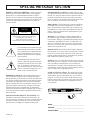 2
2
-
 3
3
-
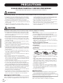 4
4
-
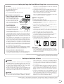 5
5
-
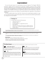 6
6
-
 7
7
-
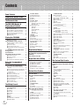 8
8
-
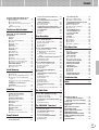 9
9
-
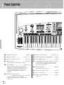 10
10
-
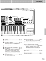 11
11
-
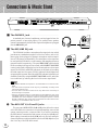 12
12
-
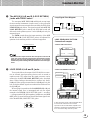 13
13
-
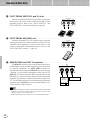 14
14
-
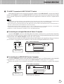 15
15
-
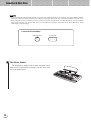 16
16
-
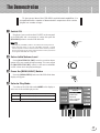 17
17
-
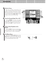 18
18
-
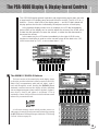 19
19
-
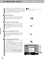 20
20
-
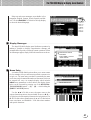 21
21
-
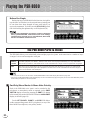 22
22
-
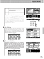 23
23
-
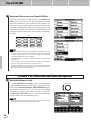 24
24
-
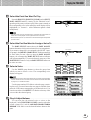 25
25
-
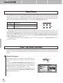 26
26
-
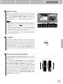 27
27
-
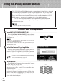 28
28
-
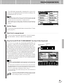 29
29
-
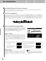 30
30
-
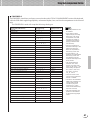 31
31
-
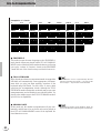 32
32
-
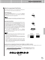 33
33
-
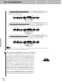 34
34
-
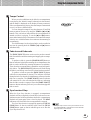 35
35
-
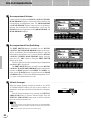 36
36
-
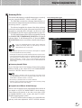 37
37
-
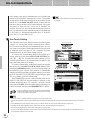 38
38
-
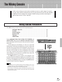 39
39
-
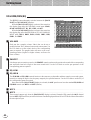 40
40
-
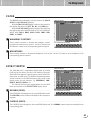 41
41
-
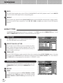 42
42
-
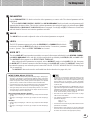 43
43
-
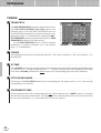 44
44
-
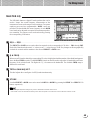 45
45
-
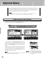 46
46
-
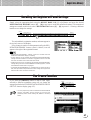 47
47
-
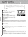 48
48
-
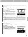 49
49
-
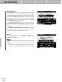 50
50
-
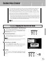 51
51
-
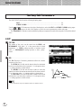 52
52
-
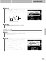 53
53
-
 54
54
-
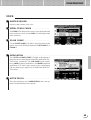 55
55
-
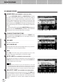 56
56
-
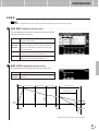 57
57
-
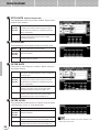 58
58
-
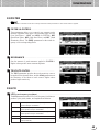 59
59
-
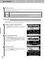 60
60
-
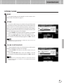 61
61
-
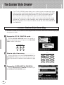 62
62
-
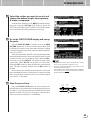 63
63
-
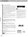 64
64
-
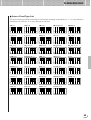 65
65
-
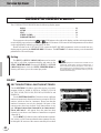 66
66
-
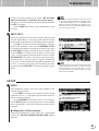 67
67
-
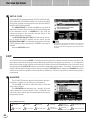 68
68
-
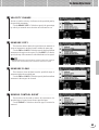 69
69
-
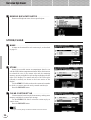 70
70
-
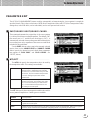 71
71
-
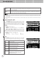 72
72
-
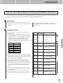 73
73
-
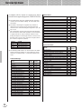 74
74
-
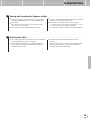 75
75
-
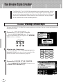 76
76
-
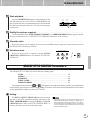 77
77
-
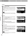 78
78
-
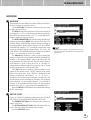 79
79
-
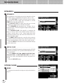 80
80
-
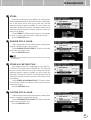 81
81
-
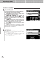 82
82
-
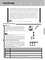 83
83
-
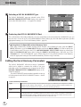 84
84
-
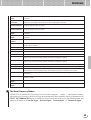 85
85
-
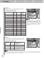 86
86
-
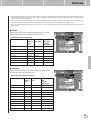 87
87
-
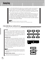 88
88
-
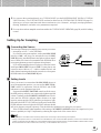 89
89
-
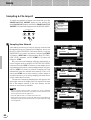 90
90
-
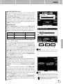 91
91
-
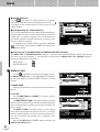 92
92
-
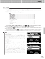 93
93
-
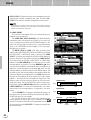 94
94
-
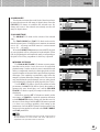 95
95
-
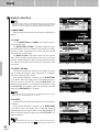 96
96
-
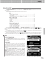 97
97
-
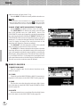 98
98
-
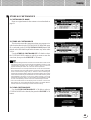 99
99
-
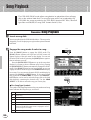 100
100
-
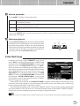 101
101
-
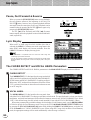 102
102
-
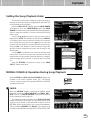 103
103
-
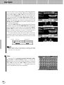 104
104
-
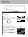 105
105
-
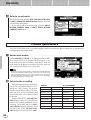 106
106
-
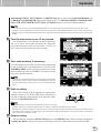 107
107
-
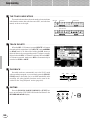 108
108
-
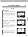 109
109
-
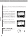 110
110
-
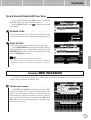 111
111
-
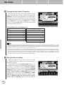 112
112
-
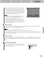 113
113
-
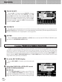 114
114
-
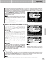 115
115
-
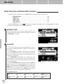 116
116
-
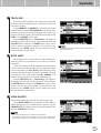 117
117
-
 118
118
-
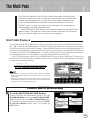 119
119
-
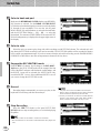 120
120
-
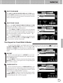 121
121
-
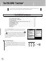 122
122
-
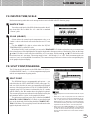 123
123
-
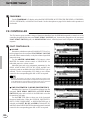 124
124
-
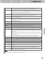 125
125
-
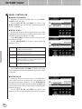 126
126
-
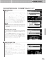 127
127
-
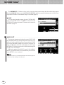 128
128
-
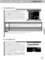 129
129
-
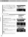 130
130
-
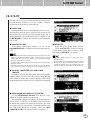 131
131
-
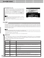 132
132
-
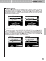 133
133
-
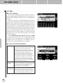 134
134
-
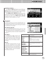 135
135
-
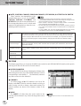 136
136
-
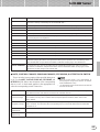 137
137
-
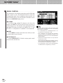 138
138
-
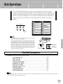 139
139
-
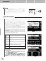 140
140
-
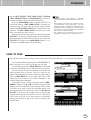 141
141
-
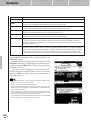 142
142
-
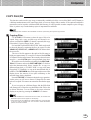 143
143
-
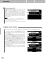 144
144
-
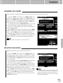 145
145
-
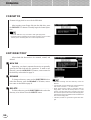 146
146
-
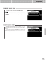 147
147
-
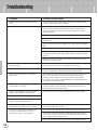 148
148
-
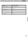 149
149
-
 150
150
-
 151
151
-
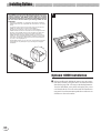 152
152
-
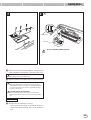 153
153
-
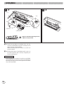 154
154
-
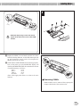 155
155
-
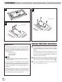 156
156
-
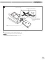 157
157
-
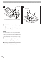 158
158
-
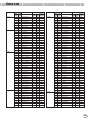 159
159
-
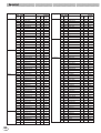 160
160
-
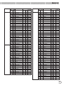 161
161
-
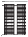 162
162
-
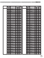 163
163
-
 164
164
-
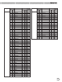 165
165
-
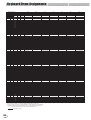 166
166
-
 167
167
-
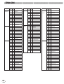 168
168
-
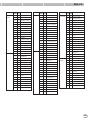 169
169
-
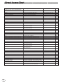 170
170
-
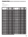 171
171
-
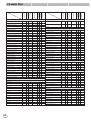 172
172
-
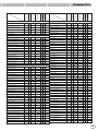 173
173
-
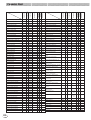 174
174
-
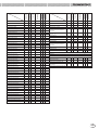 175
175
-
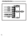 176
176
-
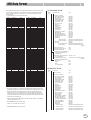 177
177
-
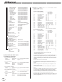 178
178
-
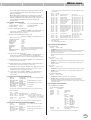 179
179
-
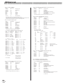 180
180
-
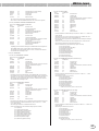 181
181
-
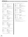 182
182
-
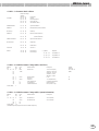 183
183
-
 184
184
-
 185
185
-
 186
186
-
 187
187
-
 188
188
-
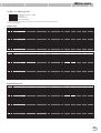 189
189
-
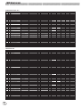 190
190
-
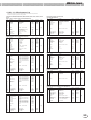 191
191
-
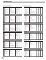 192
192
-
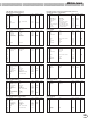 193
193
-
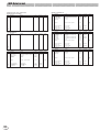 194
194
-
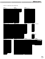 195
195
-
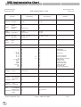 196
196
-
 197
197
-
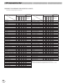 198
198
-
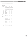 199
199
-
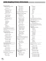 200
200
-
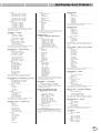 201
201
-
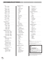 202
202
-
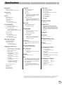 203
203
-
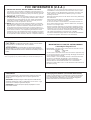 204
204
-
 205
205
-
 206
206


Yamaha PSR-8000 Benutzerhandbuch
- Kategorie
- Synthesizer
- Typ
- Benutzerhandbuch
- Dieses Handbuch eignet sich auch für
in anderen Sprachen
- English: Yamaha PSR-8000 User manual
- français: Yamaha PSR-8000 Manuel utilisateur
- español: Yamaha PSR-8000 Manual de usuario
- italiano: Yamaha PSR-8000 Manuale utente
- русский: Yamaha PSR-8000 Руководство пользователя
- Nederlands: Yamaha PSR-8000 Handleiding
- português: Yamaha PSR-8000 Manual do usuário
- dansk: Yamaha PSR-8000 Brugermanual
- polski: Yamaha PSR-8000 Instrukcja obsługi
- čeština: Yamaha PSR-8000 Uživatelský manuál
- svenska: Yamaha PSR-8000 Användarmanual
- Türkçe: Yamaha PSR-8000 Kullanım kılavuzu
- suomi: Yamaha PSR-8000 Ohjekirja
- română: Yamaha PSR-8000 Manual de utilizare
Verwandte Artikel
-
Yamaha PSR1100 Benutzerhandbuch
-
-
Yamaha W7 Bedienungsanleitung
-
-
-
-
-
-
-
Andere Dokumente
-
Korg KM-2 Benutzerhandbuch
-
-
Vox Dynamic Looper – VDL1 Bedienungsanleitung
-
Pioneer RMX-1000 Bedienungsanleitung
-
-
Panasonic SXKN7000 Bedienungsanleitung
-
 HeadRush Looperboard Schnellstartanleitung
-
-
-
Pioneer RMX-500 Schnellstartanleitung
