Seite wird geladen ...

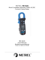
METREL MD 9210
Slim Jaws Clamp Meter
MD 9210
User Manual
Bedienungsanleitung
Navodilo za uprabo
Version 1.3, Code no. 20 751 290

2
Distributor:
METREL d.d.
Ljubljanska cesta 77
1354 Horjul
Slovenia
E-mail: [email protected]
web site: http://www.metrel.si/
Metrel GmbH
Mess und Prüftechnik
Orchideenstrasse 24
90542 Eckental -Brand
Germany
E-mail: [email protected]
Internet: http://www.metrel.de/
Metrel UK Ltd.
Test & Measurement
Unit 16, 1st Qtr Business Park
Blenheim Road
Epsom
Surrey
KT19 9QN,
Great Britain
E-mail: [email protected]
Internet: http://www.metrel.co.uk
© 2007 – 2016 METREL
Mark on your equipment certifies that this equipment meets the requirements of the EC
(European Community) regulations concerning safety and electromagnetic compatibility.
No part of this publication may be reproduced or utilized in any form or by any means
without permission in writing from METREL.

MD 9210 Slim Jaws Clamp Meter Table of contents/ Inhalt / Vsebina
3
Table of contents/ Inhalt / Vsebina
English
1 Safety ........................................................................................................................... 4
2 Cenelec Directives ........................................................................................................ 5
3 Product Description ...................................................................................................... 6
4 Operation ...................................................................................................................... 7
5 Maintenance ............................................................................................................... 13
6 Specification ............................................................................................................... 14
Deutsch
1 Sicherheit .................................................................................................................... 18
2 Cenelec-Richtlinien ..................................................................................................... 19
3 Produktbeschreibung .................................................................................................. 20
4 Betrieb ........................................................................................................................ 21
5 Wartung ...................................................................................................................... 28
6 Allgemeine Daten ....................................................................................................... 29
Slovensko
1 Varnost ....................................................................................................................... 33
2 Smernice CENELEC ................................................................................................... 34
3 Opis izdelka ................................................................................................................ 35
4 Obratovanje ................................................................................................................ 36
5 Vzdrževanje ................................................................................................................ 42
6 Tehnični podatki.......................................................................................................... 43

MD 9210 Slim Jaws Clamp Meter Safety
4
1 Safety
This manual contains information and warnings that must be followed for operating the
instrument safely and maintaining the instrument in a safe operating condition. If the
instrument is used in a manner not specified by the manufacturer, the protection
provided by the instrument may be impaired.
The meter meets the requirements for double insulation to IEC/UL/EN61010-1 Ed. 3.0,
IEC/EN61010-2-030 Ed. 1.0, IEC/EN61010-2-033 Ed. 1.0, IEC/UL/EN61010-031 Ed. 1.1
and CAN/CSA-C22.2 No. 61010-1-12 Ed. 3.0 to Category III 600Volts AC & DC.
PER IEC61010 OVERVOLTAGE INSTALLATION CATEGORY
OVERVOLTAGE CATEGORY II
Equipment of OVERVOLTAGE CATEGORY II is energy-consuming equipment to be
supplied from the fixed installation.
Note – Examples include household, office, and laboratory appliances.
OVERVOLTAGE CATEGORY III
Equipment of OVERVOLTAGE CATEGORY III is equipment in fixed installations.
Note – Examples include switches in the fixed installation and some equipment for
industrial use with permanent connection to the fixed installation.
OVERVOLTAGE CATEGORY IV
Equipment of OVERVOLTAGE CATEGORY IV is for use at the origin of the installation.
Note – Examples include electricity meters and primary over-current protection
equipment.
TERMS IN THIS MANUAL
WARNING identifies conditions and actions that could result in serious injury or even
death to the user.
CAUTION identifies conditions and actions that could cause damage or malfunction
in the instrument.
WARNING
To reduce the risk of fire or electric shock, do not expose this product to rain or moisture.
The meter is intended only for indoor use.
To avoid electrical shock hazard, observe the proper safety precautions when working
with voltages above 60 VDC or 30 VAC rms. These voltage levels pose a potential
shock hazard to the user. Before and after hazardous voltage measurements, test the
voltage function on a known source such as line voltage to determine proper meter
functioning.
Keep your hands/fingers behind the hand/finger barriers (of the meter and the test leads)
that indicate the limits of safe access of the hand-held part during measurement.
Inspect test leads, connectors, and probes for damaged insulation or exposed metal
before using the instrument. If any defects are found, replace them immediately. Only

MD 9210 Slim Jaws Clamp Meter Safety /Cenelec Directives
5
use the test lead provided with the equipment or UL Listed Probe Assembly rated CAT
III 600V or better.
This Clamp-on meter is designed to apply around or remove from uninsulated
hazardous live conductors. But still, individual protective equipment must be used if
hazardous live parts in the installation where measurement is to be carried out could be
accessible.
CAUTION
Disconnect the test leads from the test points before changing meter functions.
INTERNATIONAL ELECTRICAL SYMBOLS
!
Caution ! Refer to the explanation in this Manual
Caution ! Risk of electric shock
Earth (Ground)
Double Insulation or Reinforced insulation
Fuse
AC--Alternating Current
DC--Direct Current
Application around and removal from hazardous live conductors is permitted
2 Cenelec Directives
The instruments conform to CENELEC Low-voltage directive 2006/95/EC and
Electromagnetic compatibility directive 2004/108/EC.

MD 9210 Slim Jaws Clamp Meter Product Description
6
3 Product Description
This user's manual uses only representative model(s) for illustrations. Please refer
specification details for function availability to each model.
1 Transformer Clamp Jaw for AC current magnetic field pick up
2 Hand/Finger Barrier to indicate the limits of safe access of the meter during
measurement
3 Push-buttons for special functions & features. Also as power ON/OFF buttons for
ACA function in Twin Display Models
4 Push-buttons for special functions & features on Slide-switch Selector functions
5 Input Jack for all functions EXCEPT non-invasive ACA current function
6 Common (Ground reference) Input Jack for all functions EXCEPT non-invasive
ACA current function
7 Slide-switch Selector to turn the power ON/OFF and Select a function
8 3-3/4 digits 4000 counts LCD display(s)
9 Jaw trigger for opening the transformer clamp jaw
10 Jaw center Indicators, at where best ACA accuracy is specified
11 Jaw marking lines for ACA position error indication

MD 9210 Slim Jaws Clamp Meter Operation
7
4 Operation
CAUTION: Before and after hazardous voltage measurements, test the voltage function
on a known source such as line voltage to determine proper meter functioning.
DC Voltage, AC Voltage, Hz Frequency functions
Set slide-switch to Voltage function position(s). Inputs are made through the test leads
terminals. For Twin Display Models, slide-switch on defaults at AC voltage. Press
SELECT button momentarily to select DC voltage.
Press the Hz button momentarily to activate Hz Frequency function in the following
slide-switch functions:
Single Display Models:
DCV & ACV via the test leads; ACA via the clamp jaw
Twin Display Models:
DCV, ACV, DCA & ACA via the test leads (not available to ACA)
Note: DC 400.0mV range is designed with 1000M high input impedance for least
current drain in measuring small signals, and can cope better with most commercially
available voltage output transducers/adapters. The non-zero display reading is normal
when the meter inputs are open circuit, which will not affect actual measurement
accuracy. The meter will show close to zero readings when the inputs are shorted.
Open input is actually a floating condition, which is not a zero-volt-input condition.

MD 9210 Slim Jaws Clamp Meter Operation
8
Note: The Hz trigger level is determined by the selected function-range from where the
Hz function is activated. In ACV function:
Activating the Hz function during significant measurements can get the most appropriate
trigger level to avoid electrical noises in most cases. Electrical noise may cause
unstable Hz reading.
Activating the Hz function at AC 4.000V range (before making significant measurements)
can get lower trigger level (higher sensitivity). Hz reading may show zero when the
sensitivity is insufficient.
CAUTION
Using Resistance, Continuity, Diode or Capacitance function in a live circuit will produce
false results and may damage the instrument. In many cases the suspected component
must be disconnected from the circuit to obtain an accurate measurement reading.

MD 9210 Slim Jaws Clamp Meter Operation
9
Resistance, and Continuity functions
Inputs are made through the test leads terminals. Slide-switch on defaults at . Press
SELECT button momentarily to select Continuity function which is convenient for
checking wiring connections and operation of switches. A continuous beep tone
indicates a complete wire.
Diode test function
Inputs are made through the test leads terminals. Slide-switch on defaults at . Press
SELECT button momentarily 2 times to select Diode test function. Normal forward
voltage drop (forward biased) for a good silicon diode is between 0.400V to 0.900V. A
reading higher than that indicates a leaky diode (defective). A zero reading indicates a
shorted diode (defective). An OL indicates an open diode (defective). Reverse the test
leads connections (reverse biased) across the diode. The digital display shows OL if the
diode is good. Any other readings indicate the diode is resistive or shorted (defective).
Capacitance function
Inputs are made through the test leads terminals. Slide-switch on defaults at . Press
SELECT button momentarily 3 times to select Capacitance function.
Note:
Relative zero mode can be used to zero out the parasitic capacitance of the leads
and the internal protection circuitry of the meter when measuring low capacitance in the
order of Pico Farad (pF).
CAUTION
Discharge capacitors before making any measurements. Large value capacitors should
be discharged through an appropriate resistance load
ACA function
Inputs are made through the clamp jaws for non-invasive ACA current measurements.
For Single Display Models, set the slide-switch to select the ACA function.
For dual inputs Twin Display Models, press the OFF push button momentarily to power
on and off the separate ACA function display. The HOLD push button can also be used
as the ACA function power on hotkey. This twin display ACA function can be used
simultaneously with the voltage or any other slide-switch functions when making
measurements.

MD 9210 Slim Jaws Clamp Meter Operation
10
CAUTION (Application and removal of the Clamp-on meter)
For non-invasive ACA current measurements, press the jaw trigger and clamp the jaws
around only one single conductor of a circuit for load current measurement. Make sure
the jaws are completely closed, or else it will introduce measurement errors. Enclosing
more than one conductor of a circuit will result in differential current (like identifying
leakage current) measurement. Locate the conductor(s) at the Jaws center as much as
possible to get the best measuring accuracy. For removal, press the jaw trigger and
remove the jaws from the conductor(s).
Adjacent current-carrying devices such as transformers, motors and conductor wires will
affect measurement accuracy. Keep the jaws away from them as much as possible to
minimize influence.

MD 9210 Slim Jaws Clamp Meter Operation
11
Temperature function (Twin Display Models only)
Be sure to insert the banana plug type-K temperature bead probe AMD 9032 with
correct polarities. Slide-switch on defaults at degree C (Celsius). Press SELECT
button momentarily to select degree F (Fahrenheit). You can also use a plug adapter
AMD 9024 (Optional purchase) with banana pins to type-K socket to adapt other type-K
standard mini plug temperature probes.
A Current function (Twin Display Models only)
Inputs are made through the test leads terminals. Slide-switch on defaults at DC. Press
SELECT button momentarily to select AC.
Application notes:
The DCA function is designed especially for HVAC/R flame sensor applications. The
0.1A resolution is useful for identifying the minute current changes in flame detector
applications. Flame signal current check should indicate steady flame signal of at least
2A for a rectification type, or 1.5A for an ultraviolet type (8A for self checking
systems). If a flame signal current with inadequate strength or fluctuation beyond 10%,
check the following to avoid the risk of unwanted flame relay dropout:
For gas or oil flames (Minipeeper):
Low supply voltage
Detector location
Defective detector wiring

MD 9210 Slim Jaws Clamp Meter Operation
12
Dirty viewing windows
Faulty Minipeeper
For oil flames (Photocell):
Detector location & wiring
Smoky flame or poorly adjusted air shutter
Faulty Photocell
Temperature over 165 F (74 C) at photocell
For gas flames (Flame Rod):
Ignition interference (A flame signal current difference with the ignition both on
and off greater than 0.5A indicates the presence of ignition interference)
Insufficient ground (must be at least 4 times the detector area)
Flame lifting off burner head (ground), or not continuously in contact with the
flame rod
Temperature in excess of 600
o
F (316
o
C) at the flame electrode insulator
causing short to ground.
HOLD
The hold feature freezes the display for later view. Press the HOLD button
momentarily toggles to hold mode in the following function(s):
Single Display Models: All functions
Twin Display Models: Upper display ACA function
MAX
The max feature compares and displays the measured maximum value as fast as 30ms
with auto-ranging capability. Press the MAX button for 1 second or more toggles to
max feature in the following function(s):
Single Display Models:DCV, ACV & ACA functions
Twin Display Models:Upper display ACA function
Relative zero mode (Single Display Models only)
Relative zero mode allows the user to offset the meter consecutive measurements
with the displaying reading as the reference value. The display will now show readings
relative to the stored reference value. That is, display = reading - stored value. Press
the button momentarily toggles to relative zero mode.
Auto-ranging
Where there is more than one measuring range under a selected meter function, the
LCD annunciator “a” turns on. The meter will automatically switch to the best resolution
range when making measurements. No manual ranging selection is required.
Auto Power Off (APO)
When the meter is on, the Auto Power Off (APO) feature will switch the meter into a
sleep mode automatically to extend battery life after approximately 30 minutes of no
slide-switch nor push button operations. To wake up the meter from APO, press the
buttons momentarily or set the slide-switch to the OFF position and then slide back on
again. Always set the slide-switch to the OFF position manually when the meter is not in
use.

MD 9210 Slim Jaws Clamp Meter Maintenance
13
5 Maintenance
WARNING
To avoid electrical shock, disconnect the meter from any circuit, remove the test leads
from the input jacks and turn OFF the meter before opening the case. Do not operate
with open case.
Trouble Shooting
If the instrument fails to operate, check batteries and test leads etc., and replace as
necessary. Double check operating procedure as described in this user’s manual.
If the instrument voltage-resistance input terminal has subjected to high voltage
transient (caused by lightning or switching surge to the system) by accident or abnormal
conditions of operation, the series fusible resistors will be blown off (become high
impedance) like fuses to protect the user and the instrument. Most measuring functions
through this terminal will then be open circuit. The series fusible resistors and the spark
gaps should then be replaced by qualified technician. Refer to the LIMITED
WARRANTY section for obtaining warranty or repairing service.
Cleaning and Storage
Periodically wipe the case with a damp cloth and mild detergent; do not use abrasives
or solvents. If the meter is not to be used for periods of longer than 60 days, remove the
batteries and store them separately.
Battery replacement
The meters use standard 3V IEC-CR2032 coin batteries
In Signle Display Models:One battery is used.
In Twin Display Models:Two batteries are used. One is used for slide-switch functions,
and the other one is used for the twin display ACA function separately.
Loosen the two screws from the case bottom and remove the bottom case. Slide the
battery out the side of the holder and replace with a new battery (observe polarity).
Replace the bottom case. Re-fasten the screws.

MD 9210 Slim Jaws Clamp Meter Specification
14
6 Specification
GENERAL SPECIFICATIONS
Display: 3-3/4 digits 4000 counts LCD display(s)
Update Rate: 3 per second nominal
Polarity: Automatic
Low Battery: Below approx. 2.4V
Operating Temperature: 0C to 40C
Relative Humidity: Maximum relative humidity 80% for temperature up to 31C decreasing
linearly to 50% relative humidity at 40C
Altitude: Operating below 2000m
Storage Temperature: -20
o
C to 60
o
C, < 80% R.H. (with battery removed)
Temperature Coefficient: nominal 0.15 x (specified accuracy)/
o
C @(0
o
C ~ 18
o
C or 28
o
C ~ 40
o
C), or
otherwise specified
Sensing: Average sensing for MD9210
Overload Protections:
ACA Clamp-on jaws: AC 600A rms continuous
+/A & COM terminals: 600VDC/VAC rms
Transient protection: 6.5kV (1.2/50s surge) for all models
Safety: Meets IEC/UL/EN61010-1 Ed. 3.0, IEC/EN61010-2-032 Ed. 3.0, IEC/EN61010-2-033 Ed. 1.0,
IEC/UL/EN61010-031 Ed. 1.1 & CAN/CSA-C22.2 No. 61010-1-12 Ed. 3.0.
Measurement Category: III 600 Volts ac & dc
Pollution degree: 2
E.M.C.: Meets EN61326 (1997, 1998/A1), EN61000-4-2 (1995, 2000/A2), and EN61000-4-3 (2002)
In an RF field of 3V/m:
Capacitance function is not specified
Total Accuracy = Specified Accuracy + 65 digits
Other function ranges:
Total Accuracy = Specified Accuracy + 45 digits
Performance above 3V/m is not specified
Power Supply: 3V coin battery IEC-CR2032
One battery for Single Display Models;
Two batteries for Twin Display Models
Power Consumption: 2.8mA typical except that 3.3mA typical for ACA function
APO Timing: Idle for 30 minutes

MD 9210 Slim Jaws Clamp Meter Specification
15
APO Consumption: 5A typical on all model functions
Dimension: L190mm X W63mm X H32mm
Weight: 139 gm approx
Jaw opening & Conductor diameter: 26mm max
Accessories :
Test leads (pair),
battery(ies) installed,
user's manual,
soft carrying pouch;
Special Features:
30ms Max Hold;
Data Hold;
Relative Zero mode;
Slim jaws;
Light Weight
Electrical Specification
Accuracy is ±(% reading digits + number of digits) or otherwise specified, at 23
o
C ±5
o
C & less than 75%
R.H.
DC Voltage
RANGE
Accuracy
400.0 mV
0.3% + 4d
4.000V, 40.00V,
400.0V
0.5% + 3d
600V
1.0% + 4d
NMRR: >50dB @ 50/60Hz
CMRR: >120dB @ DC, 50/60Hz, Rs=1k
Input Impedance: 10M, 30pF nominal
(1000M for 400.0mV range)
AC Voltage
RANGE
Accuracy
50Hz ~ 500Hz
4.000V, 40.00V,
400.0V
1.5% + 5d
600V
2.0% + 5d
CMRR: >60dB @ DC to 60Hz, Rs=1k
Input Impedance: 10M, 30pF nominal
ACA Current (Clamp-on)
RANGE
Accuracy
1) 2) 3)
50Hz / 60Hz
40.00A
1.5% +8d
400.0A
1.5% +8d
600A
1.5% + 8d
1)
Induced error from adjacent
current-carrying conductor:
0.05/A
2)
Specified accuracy is from 1%
to 100% of range and for
measurements made at the jaw
center. When the conductor is not
positioned at the jaw center,
position errors introduced are:
Add 2% to specified accuracy for
measurements made BEYOND
jaw marking lines (toward jaw
opening)
3)
Add 8d to specified accuracy @
reading < 10% of range
Max Hold
Specified accuracy ± 50 digits for
changes > 25ms in duration

MD 9210 Slim Jaws Clamp Meter Specification
16
Ohms
RANGE
Accuracy
400.0
0.8% + 8d
4.000k, 40.00k,
400.0k
0.6% + 4d
4.000M
1.0% + 4d
40.00M
2.0% + 4d
Open Circuit Voltage: 0.4VDC typical
Audible Continuity Tester
Audible threshold: between 5 and 120.
Diode Tester
Open Circuit Voltage
Test Current
(Typical)
< 1.6 VDC
0.25mA
Hz Frequency
Function
Sensitivity
(Sine RMS)
Range
400.0mV
350mV
10Hz ~ 2kHz
4.000V
1V
10Hz ~ 5kHz
4.000V,
40.00V
32V
10Hz ~ 100kHz
400.0V
100V
10Hz ~ 10kHz
600V
500V
10Hz ~ 5kHz
400.0A
1)
500A
10Hz ~ 30kHz
2000A
1)
500A
10Hz ~ 30kHz
400.0A
2) 3)
60A
40Hz ~ 400Hz
Display counts: 5000
Best resolution: 0.001Hz
Accuracy: 0.5%+4d
Capacitance
RANGE
1)
Accuracy
2) 3)
500.0nF, 5.000F,
50.00F, 500.0F,
3000F
3.5% + 6d
Accuracies with film capacitor or better
Specified with battery voltage above 2.8V
(approximately half full battery). Accuracy
decreases gradually to 12% at low battery
warning voltage of approximately 2.4V

MD 9210 Slim Jaws Clamp Meter Limited warranty
17
LIMITED WARRANTY
This equipment is warranted against any defects of manufacture or materials.
During the warranty period (2 years), defective parts will be replaced, the manufacturer
reserving the right to repair or replace the product. In the event of the equipment being
returned to the after sale department or to a local agency, the outward transport is
payable by the consignor. For delivery indicate, by means of an enclosed note, as clear
as possible, the reasons for returning it. Any damage caused by shipment using not
original packing will be charged in any case to the consignor.
The manufacturer will not be responsible for any damage to persons or things.
The warranty is not valid in the following cases:
Accessories and battery are not included in warranty.
Repairs following unsuitable use of the equipment.
Repairs necessitated by attempts to repair by a person not approved by the
manufacturer.
Modification of the equipment without the explicit authorisation of the manufacturer.
Adaptation to a specific application not provided for in the specifications of the
equipment or the user manual.
Damage after a drop, a shock or flooding.
The contents of this manual must not be reproduced in any form whatsoever without the
consent of the manufacturer.
Service
The life span of the equipment is 7 years. If the equipment should not work properly,
before the service, test the battery conditions, the test leads, etc., and change them if
necessary.
If the equipment still does not work check if your operating procedure agrees with the
latter described in this manual.
In the event of returning the equipment it must be re-sent to the after-sales service of
the local Metrel distributor, the outward transport is payable by customer. The delivery
must be agreed in advance with consignee. For delivery indicate, by means of an
enclosed note, as clear as possible, the reasons for returning it. Use only the original
packing. Any damage caused by delivery with NO original packing will be charged in
any case to the consignor.
THIS WARRANTY IS EXCLUSIVE AND IS IN LIEU OF ALL OTHER WARRANTIES,
EXPRESSED OR IMPLIED, INCLUDING BUT NOT LIMITED TO ANY IMPLIED
WARRANTY OR MERCHANTABILITY OR FITNESS FOR A PARTICULAR PURPOSE
OR USE. METREL WILL NOT BE LIABLE FOR ANY SPECIAL, INDIRECT,
INCIDENTAL OR CONSEQUENTIAL DAMAGES.
PRINTED ON RECYCLABLE PAPER, PLEASE RECYCLE

MD 9210 Leistungsmesszange Sicherheit
18
1 Sicherheit
Diese Anleitung enthält Informationen und Warnungen, die befolgt werden müssen, um
das Instrument sicher zu betreiben und in sicherem Betriebszustand zu erhalten. Wenn
das Gerät auf eine Weise benutzt wird, die nicht vom Hersteller angegeben wurde, kann
der Schutz, den das Gerät bietet, beeinträchtigt werden.
Das Messgerät erfüllt die Anforderungen für Schutzisolierung nach IEC/UL/EN61010-1
Ed. 3.0, IEC/EN61010-2-030 Ed. 1.0, IEC/EN61010-2-033 Ed. 1.0, IEC/UL/EN61010-031
Ed. 1.1 und CAN/CSA-C22.2 No. 61010-1-12 Ed. 3.0 nach CAT III AC & DC geschützt.
ÜBERSPANNUNGS-INSTALLATIONSKATEGORIE NACH IEC61010
ÜBERSPANNUNGSKATEGORIE II
Eine Einrichtung der ÜBERSPANNUNGSKATEGORIE II ist eine energieverbrauchende
Einrichtung, die von der festen Installation versorgt werden muss.
Anmerkung – Beispiele sind Haushalts-, Büro- und Laborgeräte.
ÜBERSPANNUNGSKATEGORIE III
Eine Einrichtung der ÜBERSPANNUNGSKATEGORIE III ist eine Einrichtung in festen
Installationen.
Anmerkung – Beispiele sind Schalter in der festen Installation und einige Einrichtungen
für den industriellen Gebrauch mit dauernder Verbindung zur festen Installation.
ÜBERSPANNUNGSKATEGORIE IV
Eine Einrichtung der ÜBERSPANNUNGSKATEGORIE IV ist zum Gebrauch am
Ursprung der Installation bestimmt. Anmerkung – Beispiele sind Stromzähler und
primärer Überstromschutzeinrichtungen.
BEGRIFFE IN DIESER ANLEITUNG
WARNUNG Gibt Bedingungen oder Aktionen an, die zu schweren Verletzungen oder
sogar zum Tod des Anwenders führen könnten.
VORSICHT Gibt Bedingungen oder Aktionen an, die Beschädigungen oder
Fehlfunktionen des Instruments verursachen könnten.
WARNUNG
Um die Feuer- oder Stromschlaggefahr zu reduzieren, setzen Sie dieses Produkt nicht
Regen oder Feuchtigkeit aus. Das Messgerät ist nur für den Gebrauch in Innenräumen
bestimmt.
Um Stromschlaggefahr zu vermeiden, beachten Sie die geeigneten
Sicherheitsmaßnahmen bei Arbeiten an Spannungen über 60 VDC oder 30 V
eff
. Diese
Spannungspegel stellen eine mögliche Stromschlaggefahr für den Anwender dar.
Prüfen Sie vor und nach Messungen an gefährlichen Spannungen die
Spannungsfunktion an einer bekannten Quelle, wie etwa der Netzspannung, um die
einwandfreie Funktion des Messgerätes zu überprüfen.
Bleiben Sie mit Ihren Händen/Fingern hinter den Hand-/Fingerbarrieren (des
Messgeräts und der Prüfleitungen), welche die Abgrenzungen des während der

MD 9210 Leistungsmesszange Specification/Cenelec-Richtlinien
19
Messung sicher in der Hand zu haltenden Teils angeben. Untersuchen Sie vor der
Verwendung des Instruments die Prüfleitungen, Steckverbinder und Sonden auf
beschädigte Isolierung oder frei liegendes Metall. Wenn Sie Defekte finden, wechseln
Sie die Teile sofort aus.
Dieses Zangenmessgerät ist dafür vorgesehen, um gefährliche Spannung führende
unisolierte Leiter angebracht oder davon abgenommen zu werden. Dennoch müssen
persönliche Schutzeinrichtungen verwendet werden, wenn gefährliche Spannung
führende Teile in der Anlage zugänglich sein könnten, in der gemessen werden soll.
Verwenden Sie nur die Messleitung mit der Ausrüstung zur Verfügung gestellt, oder UL
Listed Probe Versammlung bewertet CAT III 600 V oder besser.
VORSICHT
Vor dem Umschalten von Messgerätefunktionen trennen Sie die Prüfleitungen von den
Prüfpunkten.
INTERNATIONALE ELEKTROSYMBOLE
!
Vorsicht! Siehe Erklärungen in dieser Anleitung
Vorsicht! Es besteht die Gefahr eines Stromschlags!
ERDE (ERDUNG)
Doppelisolierung oder Schutzisolierung
Sicherung
AC--WECHSELSTROM
DC--Gleichstrom
Anbringen um gefährliche Spannung führende Leiter oder Abnehmen von ihnen
ist gestattet.
2 Cenelec-Richtlinien
Die Instrumente entsprechen der CENELEC-Niederspannungsrichtlinie 2006/95/EC und
der Richtlinie „Elektromagnetische Verträglichkeit“ 2004/108/EC.

MD 9210 Leistungsmesszange Produktbeschreibung
20
3 Produktbeschreibung
Diese Bedienungsanleitung verwendet repräsentative Modell(e) nur zur Illustration. Bitte
schauen Sie in den Einzelheiten der Spezifikation nach, welche Funktionen für jedes
Modell zur Verfügung stehen.
1 Transformatorzange zum Erfassen des Wechselstrom-Magnetfelds
2 Hand-/Fingerbarriere zur Markierung der Abgrenzungen des während der Messung
sicher zugänglichen Teils des Messgerätes.
3 Tasten für Sonderfunktionen. Auch als EIN-AUS-Tasten für Wechselstromfunktionen
bei Doppeldisplay-Modellen
4 Tasten für Sonderfunktionen bei Schiebe-Wahlschalterfunktionen
5 Eingangsbuchse für alle Funktionen AUSSER der nichtinvasiven
Wechselstromfunktion
6 Gemeinsame (Bezugsmasse-)Eingangsbuchse für alle Funktionen AUSSER der
nichtinvasiven Wechselstromfunktion
7Schiebe-Wahlschalter zum EIN-/AUS-Schalten und Wählen einer Funktion
8 3-3/4-stellige(s) (4000 Zähler) LCD-Display(s)
9 Zangenbetätigung zum Öffnen der Transformatorzange
10 Anzeigen für Zangenmitte, in der die beste Wechselstromgenauigkeit spezifiziert ist
11 Zangenmarkierungslinien für Anzeige eines Wechselstrom-Positionsfehlers
/