Iluminarc LOGIC Wall Panel Expansion Kit 8-port Installationsanleitung
- Typ
- Installationsanleitung

English EN
Español ES
Français FR
Deutsch DE
Nederlands NL
Installation Instructions
Model ID: LOGICWPEXPANDKIT8

Intentionally Left Blank Page

EN
1
LΩGIC Wall Panel Expand Kit8 Installation Instructions Rev. 1
INSTALLATION INSTRUCTIONS
About this Guide
These Installation Instructions include important information about the installation of the LΩGIC Wall Panel Expand Kit8.
Safety Notes
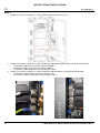
What is Included
Product Overview
Installation Instructions
Do the following to install the LΩGIC Wall Panel Expand Kit8 in the LΩGIC Wall Panel 16-Port:
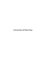
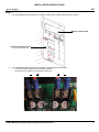
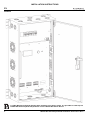
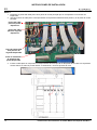
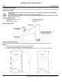
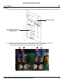
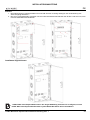
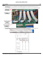
Step 1
1. Unplug the LΩGIC Wall Panel 16-Port from power.
2. Open the front panel of the LΩGIC Wall Panel 16-Port.
3. Use a #2 Phillips-head screwdriver and a 2.5 mm hex wrench to remove the indicated screws.
• Power must be turned off and disconnected when working inside the LΩGIC Wall Panel 16-Port.
• This product must be installed by a qualified and competent electrician.
• Observe all safety measures during installation (no metal jewelry, utilize a grounding mat, etc.).
• 8-port POE output board
• Power supply
• DIN rail breaker
• 6 output board screws
• 4 power supply screws
• Ribbon cable
glish
DIN rail breaker
Power supply
with screws
Ribbon cable
8-port POE
(Power Over Ethernet)
output board
with screws

2
EN
INSTALLATION INSTRUCTIONS
LΩGIC Wall Panel Expand Kit8 Installation Instructions Rev. 1
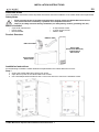
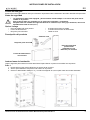
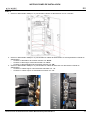
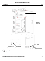
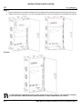
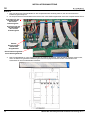
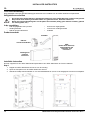
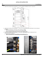
Step 2
1. Carefully remove the breaker cover and open the service access panel.
2. Remove the applicable plugs from the breaker cover and service access panel.
Do not remove the plugs for an Expand Kit unless installing an Expand Kit in that slot.
Breaker cover
Service
access panel
First Expand Kit
plug
Second Expand Kit
plug Second Expand Kit
plugs
First Expand Kit
plugs

EN
3
LΩGIC Wall Panel Expand Kit8 Installation Instructions Rev. 1
INSTALLATION INSTRUCTIONS
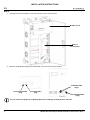
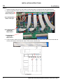
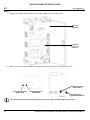
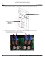
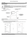
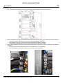
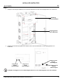
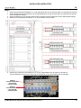
Step 3
1. Use a #2 Phillips-head screwdriver to install the 8-port POE output board with the 6 screws.
2. Use a #2 Phillips-head screwdriver to install the output board power cables.
• Connect the black cables to the terminals marked “-”.
• Connect the red cables to the terminals marked “+”.
8-port POE output board
(in the first Expand Kit slot)
Master control board

4
EN
INSTALLATION INSTRUCTIONS
LΩGIC Wall Panel Expand Kit8 Installation Instructions Rev. 1
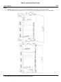
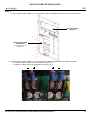
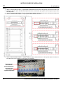
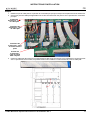
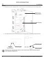
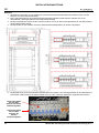
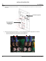
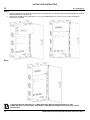
Step 4
1. Identify the ribbon cable port on the master control board which corresponds with the Expand Kit slot.
2. Open the applicable ribbon cable ports on the 8-port POE output board and on the master control board.
3. Insert the ribbon cable into the corresponding ports in such a way that when viewing the circuit boards with the
access panel open the blue tips are visible. Then close the ribbon ports.
First Expand Kit
ribbon cable port
Second Expand Kit
ribbon cable port
First Expand Kit
8-port POE
output board
Second Expand Kit
8-port POE
output board

EN
5
LΩGIC Wall Panel Expand Kit8 Installation Instructions Rev. 1
INSTALLATION INSTRUCTIONS
Step 5
1. Use a #2 Phillips-head screwdriver to install the power supply with the 4 screws.
2. Use a #2 Phillips-head screwdriver to install the AC power cables on the left of the power supply.
• Connect the white cable to the terminal marked “AC/N”.
• Connect the black cable to the terminal marked “AC/L”.
• Connect the Yellow/Green cable to the terminal marked “FG”.
3. Use a #2 Phillips-head screwdriver to install the DC output cables on the right of the power supply.
• Connect the black cables to the terminals marked “-V”.
• Connect the red cables to the terminals marked “+V”.

6
EN
INSTALLATION INSTRUCTIONS
LΩGIC Wall Panel Expand Kit8 Installation Instructions Rev. 1
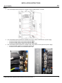
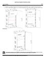
Step 6
1. Use a #2 Phillips-head screwdriver to loosen the left-most rail clamp and slide it off the rail.
2. Slide the Expand Kit DIN rail breaker onto the rail until it is up against the adjacent DIN rail breaker.
3. Slide the rail clamp back onto the rail until it is up against the Expand Kit DIN rail breaker.
4. Use a #2 Phillips-head screwdriver to tighten the rail clamp.
5. Use a #2 Phillips-head screwdriver to install the power cables to the DIN rail breaker, with the white cables on the
right and the black cables on the left.
First Expand Kit
DIN rail breaker
Second Expand Kit
DIN rail breaker

EN
7
LΩGIC Wall Panel Expand Kit8 Installation Instructions Rev. 1
INSTALLATION INSTRUCTIONS
Step 7
1. Carefully fit the breaker cover over the DIN rail breakers and close the service access panel.
2. Use a #2 Phillips-head screwdriver and a 2.5 mm hex wrench to install the previously removed screws.

8
EN
INSTALLATION INSTRUCTIONS
LΩGIC Wall Panel Expand Kit8 Installation Instructions Rev. 1
Finished
1 LΩGIC Wall Panel Expand Kit8 has been installed in the above image. It is possible to install up to 2
LΩGIC Wall Panel Expand Kit8 products in each LΩGIC Wall Panel 16-Port.

ES
9
Instrucciones de instalación de LΩGIC Wall Panel Expand Kit8 Rev. 1
INSTRUCCIONES DE INSTALACIÓN
Acerca de esta guía
Estas instrucciones de instalación incluyen información importante sobre la instalación del LΩGIC Wall Panel Expand Kit8.
Notas de seguridad
Qué se incluye
Descripción del producto
Instrucciones de instalación
Haga lo siguiente para instalar el LΩGIC Wall Panel Expand Kit8 en el panel mural LΩGIC de 16 puertos:
Paso 1
1. Desenchufe el panel mural LΩGIC de 16 puertos de la corriente.
2. Abra el panel delantero del panel mural LΩGIC de 16 puertos.
3. Utilice un destornillador Phillips n.º 2 y una llave hexagonal de 2,5 mm para retirar los tornillos indicados.
• La alimentación debe estar apagada y desconectada cuando trabaje en el interior del panel mural
LΩGIC de 16 puertos.
• Este producto debe ser instalado por un electricista calificado y competente.
• Respete todas las medidas de seguridad durante la instalación (no lleve joyas metálicas, utilice una
alfombrilla de toma de tierra, etc.).
• Placa de salida POE de 8 puertos
• Fuente de alimentación
• Disyuntor para carril DIN
• 6 tornillos de la placa de salida
• 4 tornillos de la fuente de alimentación
• Cable de cinta
pañol
Disyuntor para carril DIN
Fuente de alimentación
con tornillos
Cable de cinta
Placa de salida de 8
puertos POE
(alimentación por
Ethernet) con tornillos

10
ES
INSTRUCCIONES DE INSTALACIÓN
Instrucciones de instalación de LΩGIC Wall Panel Expand Kit8 Rev. 1
Paso 2
1. Extraiga con cuidado la tapa del disyuntor y abra el panel de acceso de servicio.
2. Retire los tapones correspondientes de la tapa del disyuntor y del panel de acceso de servicio.
No retire los tapones para un Expand Kit a menos que instale un Expand Kit en esa ranura.
Tapa del
disyuntor
Panel de
acceso de
servicio
Tapón del primer
Expand Kit
Tapón del segundo
Expand Kit Tapones del
segundo Expand Kit
Tapones del primer
Expand Kit

ES
11
Instrucciones de instalación de LΩGIC Wall Panel Expand Kit8 Rev. 1
INSTRUCCIONES DE INSTALACIÓN
Paso 3
1. Utilice un destornillador Phillips n.º 2 para instalar la placa de salida POE de 8 puertos con los 6 tornillos.
2. Utilice un destornillador Phillips n.º 2 para instalar los cables de alimentación de la placa de salida.
• Conecte los cables negros a los terminales marcados con “-”.
• Conecte los cables rojos a los terminales marcados con “+”.
Placa de salida POE
de 8 puertos
(en la ranura del primer
Expand Kit)
Placa de control
principal

12
ES
INSTRUCCIONES DE INSTALACIÓN
Instrucciones de instalación de LΩGIC Wall Panel Expand Kit8 Rev. 1
Paso 4
1. Identifique el puerto del cable plano de la placa de control principal que se corresponde con la ranura del
Expand Kit.
2. Abra los puertos de cable plano correspondientes en la placa de salida POE de 8 puertos y en la placa de control
principal.
3. Inserte el cable plano en los puertos correspondientes de forma que al ver las placas de circuitos con el panel de
acceso abierto se vean las puntas azules. A continuación, cierre los puertos de cinta.
Puerto del cable
plano del primer
Expand Kit
Puerto del cable
plano del segundo
Expand Kit
Placa de salida POE
de 8 puertos del
primer Expand Kit
Placa de salida POE
de 8 puertos del
segundo Expand Kit

ES
13
Instrucciones de instalación de LΩGIC Wall Panel Expand Kit8 Rev. 1
INSTRUCCIONES DE INSTALACIÓN
Paso 5
1. Utilice un destornillador Phillips n.º 2 para instalar la fuente de alimentación con los 4 tornillos.
2. Utilice un destornillador Phillips n.º 2 para instalar los cables de alimentación CA a la izquierda de la fuente de
alimentación.
• Conecte el cable blanco al terminal marcado con “AC/N”.
• Conecte el cable negro al terminal marcado con “AC/L”.
• Conecte el cable amarillo/verde al terminal marcado con “FG”.
3. Utilice un destornillador Phillips n.º 2 para instalar los cables de salida CC a la derecha de la fuente de
alimentación.
• Conecte los cables negros a los terminales marcados con “-V”.
• Conecte los cables rojos a los terminales marcados con “+V”.

14
ES
INSTRUCCIONES DE INSTALACIÓN
Instrucciones de instalación de LΩGIC Wall Panel Expand Kit8 Rev. 1
Paso 6
1. Utilice un destornillador Phillips n.º 2 para aflojar la abrazadera del carril más a la izquierda y deslícela fuera del carril.
2. Deslice el disyuntor para carril DIN del Expand Kit sobre el carril hasta que quede contra el disyuntor para carril
DIN adyacente.
3. Vuelva a deslizar la abrazadera sobre el carril hasta que quede contra el disyuntor para carril DIN del Expand Kit.
4. Utilice un destornillador Phillips n.º 2 para apretar la abrazadera del carril.
5. Utilice un destornillador Phillips n.º 2 para instalar los cables de alimentación en el disyuntor para carril DIN, con
los cables blancos a la derecha y los negros a la izquierda.
Disyuntor para
carril DIN del
primer Expand Kit
Disyuntor para
carril DIN del
segundo Expand Kit

ES
15
Instrucciones de instalación de LΩGIC Wall Panel Expand Kit8 Rev. 1
INSTRUCCIONES DE INSTALACIÓN
Paso 7
1. Coloque con cuidado las tapas sobre los disyuntores para carril DIN y cierre el panel de acceso de servicio.
2. Utilice un destornillador Phillips n.º 2 y una llave hexagonal de 2,5 mm para instalar los tornillos retirados antes.
Terminado
En la imagen anterior se ha instalado un LΩGIC Wall Panel Expand Kit8. Es posible instalar hasta dos
productos LΩGIC Wall Panel Expand Kit8 en cada panel mural LΩGIC de 16 puertos.

16
FR
INSTRUCTIONS D’INSTALLATION
LΩGIC Wall Panel Expand Kit8 Instructions d’installation Rév. 1
À propos de ce guide
Ces instructions d’installation contiennent des informations importantes sur l’installation du LΩGIC Wall Panel Expand Kit8.
Notes de sécurité
Contenu de la boîte
Aperçu du produit
Instructions d’installation
Procédez comme suit pour installer le LΩGIC Wall Panel Expand Kit8 dans le LΩGIC Wall Panel 16-Port :
Étape 1
1. Débranchez le LΩGIC Wall Panel 16-Port de l’alimentation.
2. Ouvrez le panneau avant du LΩGIC Wall Panel 16-Port.
3. Utilisez un tournevis cruciforme n° 2 et une clé hexagonale de 2,5 mm pour retirer les vis indiquées.
• L’alimentation doit être coupée et déconnectée lorsque vous travaillez à l’intérieur de LΩGIC Wall
Panel 16-Port.
• Ce produit doit être installé par un électricien qualifié et compétent.
• Respectez toutes les mesures de sécurité lors de l’installation (pas de bijoux en métal, utiliser un tapis
de mise à la terre, etc.).
• Carte de sortie POE à 8 ports
• Alimentation
• Disjoncteur sur rail DIN
• 6 vis de la carte de sortie
• 4 vis d’alimentation
• Câble plat
ançais
Disjoncteur sur
rail DIN
Alimentation
avec vis
Câble plat
Carte de sortie POE
(Power Over Ethernet)
à 8 ports avec vis

FR
17
LΩGIC Wall Panel Expand Kit8 Instructions d’installation Rév. 1
INSTRUCTIONS D’INSTALLATION
Étape 2
1. Retirez délicatement le couvercle du disjoncteur et ouvrez le panneau d’accès de service.
2. Retirez les fiches applicables du couvercle du disjoncteur et du panneau d’accès de service.
Ne retirez pas les fiches d’un kit d’extension à moins d’installer un kit d’extension dans cet
emplacement.
Couvercle du
disjoncteur
Panneau
d’accès aux
services
Premier kit de
prise d’extension
Deuxième kit de
prise d’extension Deuxième kit de
prises d’extension
Premier kit de
prises
d’extension

18
FR
INSTRUCTIONS D’INSTALLATION
LΩGIC Wall Panel Expand Kit8 Instructions d’installation Rév. 1
Étape 3
1. Utilisez un tournevis cruciforme n° 2 pour installer la carte de sortie POE à 8 ports avec les 6 vis.
2. Utilisez un tournevis cruciforme n° 2 pour installer les câbles d’alimentation de la carte de sortie.
• Connectez les câbles noirs aux bornes marquées « -».
• Connectez les câbles rouges aux bornes marquées « +».
Carte de sortie POE
à 8 ports
(dans le premier
emplacement du kit
d’extension)
Panneau de
commande principal
Seite wird geladen ...
Seite wird geladen ...
Seite wird geladen ...
Seite wird geladen ...
Seite wird geladen ...
Seite wird geladen ...
Seite wird geladen ...
Seite wird geladen ...
Seite wird geladen ...
Seite wird geladen ...
Seite wird geladen ...
Seite wird geladen ...
Seite wird geladen ...
Seite wird geladen ...
Seite wird geladen ...
Seite wird geladen ...
Seite wird geladen ...
Seite wird geladen ...
Seite wird geladen ...
Seite wird geladen ...
-
 1
1
-
 2
2
-
 3
3
-
 4
4
-
 5
5
-
 6
6
-
 7
7
-
 8
8
-
 9
9
-
 10
10
-
 11
11
-
 12
12
-
 13
13
-
 14
14
-
 15
15
-
 16
16
-
 17
17
-
 18
18
-
 19
19
-
 20
20
-
 21
21
-
 22
22
-
 23
23
-
 24
24
-
 25
25
-
 26
26
-
 27
27
-
 28
28
-
 29
29
-
 30
30
-
 31
31
-
 32
32
-
 33
33
-
 34
34
-
 35
35
-
 36
36
-
 37
37
-
 38
38
-
 39
39
-
 40
40


