
03/2021
WALSER GmbH & Co. KG
Senefelderstrasse 23
86368 Gersthofen
Germany
info@walser.de
ww.walser.de
Made in China
Gebrauchsanleitung
Instruction Manual
GALGENSTATIV WT-501
BOOM STAND WT-501

2 3
D Gebrauchsanleitung
Mit dem Walimex pro Galgenstativ WT-501 erhalten Sie ein tragfähiges,
stabiles Galgenstativ der Spitzenklasse. Nutzen Sie Equipment für Ihre Foto-
oder Filmarbeiten in der dritten Dimension. Die hochwertige Verarbeitung
und Produktqualität wird Sie überzeugen und Ihnen viele Jahre Zufriedenheit
geben.
Bestimmungsgemäße Verwendung
Dieses Galgenstativ, bestehend aus einem Lampenstativ und einem Ausleger
mit Klemmbefestigung, dient dazu, für Foto- und Filmarbeiten Licht oder an-
deres leichtes Equipment (z.B. ein Mikrofon) vor, über, unter oder hinter das
Motiv bringen zu können. Konstruiert für den Einsatz zur Nutzung bei Foto-
und Filmaufnahmen in privaten Studios und Haushalten sowie in industriellen
oder gewerblichen Foto- und Filmstudios. Zur Verwendung in Innenräumen
und bei Trockenheit im Freien. Speziell für die Anforderungen von Foto- und
Videoaufnahmen entwickelt.
Nicht geeignet zum Befestigen oder Führen von Kameras.
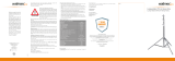
WARNUNG
Mittelsäulensegmente mit Vorspannung!
Achten Sie beim Öffnen der Stativverschlüsse (4) strengstens darauf, ge-
nügend Abstand zum oberen Ende des Statives einzuhalten und beugen
Sie sich nicht über das Stativ. Im Auslieferungszustand stehen die Federn
in den Segmenten der Mittelsäulen unter Spannung. Beim Öffnen der
Verschlussklemmen können die Mittelsäulenelemente um bis zu 20 cm
herausschnellen. Dies kann zu Verletzungen führen.
Aufbau des Stativs
Öffnen Sie die Stativverschlüsse (4) an der Mittelsäule. Vorsicht, die Mittel-
säulensegmente stehen unter Vorspannung und können herausschnellen!.
Schließen Sie die Stativverschlüsse wieder. Lösen Sie anschließend die
Feststellschraube der Stativbeinverriegelung der Winkeleinstellung (5).
Ziehen Sie die Stativbeine (8) nach außen und drücken Sie den Stativstern
(6) nach unten. Hierdurch werden die Stativbeine gespreizt. Stellen Sie den
gewünschten Winkel der Stativbeine ein. Für eine optimale Standfestigkeit
1
2
4
5
8
6
3
3
7
2
A) Bauteile
1 Befestigungsadapter 5/8 Zoll Spigot
2 Klemmadapter
3 Verschlussklemmen
4
Stativverschlüsse
5 Feststellschraube Verriegelung für
Stativbein Winkeleinstellung
6 Stativstern
7 Klemmhebel
8 Stativbeine
A) Components
1 Mounting adapter 5/8 inch spigot
2 Clamping adapter
3 Locking clamps
4 Stand locks
5 Locking screws for light stand
leg angle adjustment
6 Stand star
7 Clamping lever
8
Stand legs

4 5
Mittelsäule des Stativs bzw. den Ausleger. Mit dem Klemmhebel (7) werden
diese Elemente aufeinandergedrückt und so gegen Verdrehen gesichert. Zu-
sätzlich erlaubt die Zahnung der Rosette in der Mitte, den Anstellwinkel des
Auslegers absolut verdrehsicher festzulegen. Ziehen Sie eine zweite Person
zur Montage hinzu.
Als Vorbereitung ziehen Sie die Mittelsäule des Stativs auf die notwendige
Höhe aus. Zur Montage des Klemmadapters am Stativ lösen Sie zunächst
den Klemmhebel (7) so weit, dass Sie die ersten beiden Elemente über die
Mittelsäule des Stativs stülpen können. Drehen Sie sich die beiden Elemente
so zurecht, dass die Mittelsäule in einer von der Größe passenden Ausspa-
rung ruht. Achten Sie darauf, auf beiden Seiten die Aussparung gleicher
Größe zu wählen, damit die Belastung gleich verteilt wird.
Halten Sie nun die Elemente, die die Mittelsäule des Stativs umschließen,
mit einer Hand geschlossen. Dies gibt Ihnen den Raum, den Ausleger auf
gleiche Weise in die anderen beiden Elemente einzulegen.
Drehen Sie nun den Klemmhebel (7) wieder so weit zu, dass sowohl das
Stativ als auch der Ausleger nicht mehr herausrutschen können.
Bewegen Sie nun den Klemmadapter auf die gewünschte Höhe. Drehen Sie
den Ausleger in den gewünschten Winkel und ziehen Sie ihn so weit aus wie
gewünscht. Lassen Sie hierbei genug Platz für das Gegengewicht. Achten Sie
darauf, dass die Zähne der Rosette im Klemmadapter ineinandergreifen und
einrasten können. Schrauben Sie nun den Klemmhebel ganz zu.
Der Ausleger ist nun montiert und wie gewünscht eingestellt.
Montage von Equipment am Ausleger
Der Ausleger ist ausziehbar und verfügt an der Spitze über einen 5/8“
Spigot-Adapter. An diesem können Sie Equipment aller Art befestigen.
Beachten Sie die maximale Belastbarkeit, siehe Technische Daten.
Um die Standfestigkeit des Stativs zu erhalten, liegt ein 4,4 kg schweres
Gegengewicht bei. Nutzen Sie dieses am hinteren Ende des Auslegers auf
der anderen Seite des Klemmadapters, um die Hebelwirkung des montierten
Equipments zu kompensieren. Ziehen Sie eine zweite Person zur Montage
hinzu.
Zur Montage von Equipment unter Einbeziehung des Gegengewichts be-
festigen Sie zuerst das Gegengewicht auf dem hinteren Ende des Auslegers
direkt an der Mittelsäule des Stativs, indem sie die Klemme öffnen, es auf-
setzen und die Klemme wieder anziehen. Ziehen Sie nun den Ausleger auf
die gewünschte Länge aus und befestigen Sie das gewünschte Equipment
abrutschsicher am 5/8“ Spigot, indem Sie darauf achten, die Schraube am
empfehlen wir eine breite Spreizung der Stativbeine. Vorsicht beim Arbeiten
mit den Stativbeinen, es besteht Klemmgefahr. Fixieren Sie die Stativbeine
durch das Festziehen der Stativbein-Verriegelungsschraube (5). Beachten
Sie, dass der untere Gummipuffer der Teleskopmittelsäule nicht den Boden
berühren darf, dies beeinträchtigt die Stabilität des Stativs. Verfahren Sie
beim Zusammenlegen des Stativs in umgekehrter Reihenfolge.
Höhenverstellung
Das Stativ verfügt über eine zweiteilige, ausziehbare Teleskopmittelsäule.
Mithilfe der Stativverschlüsse (4) arretieren Sie die Verschlussklemmen der
Mittelsäule (3). Lösen Sie zur Höheneinstellung des Statives die Stativ-
verschlüsse (4) durch ein Drehen gegen den Uhrzeigersinn. Vorsicht, die
Mittelsäulensegmente stehen unter Vorspannung und können herausschnel-
len! Stellen Sie die gewünschte Höhe ein und schließen Sie die Verschluss-
klemme wieder fest. Kontrollieren Sie abschließend durch ein Drücken der
Mittelsäulenelemente nach unten, ob sämtliche Verschlüsse korrekt xiert
sind. Das Stativ ist jetzt einsatzbereit.
Montage von Equipment auf dem Stativ
Am oberen Ende der Mittelsäule bendet sich ein Befestigungsadapter
(1). Dieser verfügt über einen als 16 mm Zapfen oder auch 5/8 Zoll Spigot
bekannten Anschluss.
Mithilfe dieses Adapters lassen sich Geräte wie Studioblitze, Leuchten,
Softboxen, Polestangen uvm. per genormter Halterung befestigen. Schrau-
ben Sie zur Befestigung Ihres Equipments die Arretierungsschraube der
Gerätehaltung Ihres zu befestigenden Zubehörs etwas heraus und führen Sie
die Gerätehalterung Ihres Equipments von oben in den Stativadapter (1) ein.
Ziehen Sie anschließend die Schraube wieder fest an. Achten Sie hierbei auf
die korrekte Positionierung der Halterung. Die Schraube muss am dünneren
Teil des Befestigungsadapters (1) festgeschraubt werden. Hierdurch wird
ein Lösen der Halterung inkl. Ihres Equipments zuverlässig verhindert. Auf
dem oberen Ende des Befestigungsadapters (1) ist zusätzlich ein 1/4 Zoll
Anschlussgewinde nutzbar. Auch hieran können Sie passendes Equipment
befestigen.
Montage des Auslegers am Stativ
Der Ausleger, bisweilen auch Galgen oder Boom genannt, wird mit Hilfe
eines Klemmadapters (2) am Stativ befestigt. Beachten Sie hierbei den
Aufbau: Der Klemmadapter besteht aus vier Elementen, die durch eine
Achse zusammengehalten werden. Jeweils zwei der Elemente umgreifen die

6 7
dünnen Teil des Spigots anzuziehen. Halten Sie den Ausleger ab jetzt mit ei-
ner Hand fest, um ein Absinken oder Kippen zu verhindern. Verschieben Sie
das Gegengewicht am Ausleger und / oder den Ausleger in der Halterung
so weit, bis Sie ein Gleichgewicht zwischen Equipment und Gegengewicht
erreicht haben. Achten Sie darauf, dass das Equipment und der Ausleger fest
montiert sind und dass das Stativ sicher steht, bevor Sie loslassen.
Empfehlenswertes Zubehör zur Erhöhung der Standfestigkeit
Beim Einsatz von schwerem Equipment, vor allem in Kombination mit einer
großen Auszugshöhe, kann es notwendig sein, die Standfestigkeit des
Statives durch zusätzliche Beschwerungsmaßnahmen zu erhöhen. Hierfür
empfehlen wir die Verwendung von speziellen Sandsäcken oder Stativge-
wichten. Diese gewährleisten auch bei widrigen Bedingungen die optimale
Standfestigkeit Ihres Statives. Passende Zubehörartikel nden Sie in unserem
Webshop www.foto-walser.de unter:
Artikelnummer, Bezeichnung
15537 Walimex pro Sandsack
15876 Walimex pro Stativgewicht, 3 kg
13739 Walimex Gewicht für Stangen & Galgenstative, 4,4 kg
Benutzungshinweise und Pege des Stativs und des Auslegers
■Beachten Sie, dass Lampenstative auf einem ausreichend belastbaren,
ebenen Untergrund aufgestellt werden müssen, um eine maximale Stabili-
tät und Traglast zu gewährleisten.
■Beachten Sie die Hinweise bzgl. der maximalen Belastbarkeit Ihres Stativ-
modells (siehe Technische Daten)
■Berücksichtigen Sie, dass die angegebenen Belastungswerte für zentral
auf dem Stativ platziertes Equipment sowie einen ausbalancierten Aus-
leger gelten. Je nach verwendetem Equipment (und der auftretenden
Hebelwirkung) können die maximalen Belastungswerte vom angegebenen
Höchstwert abweichen.
■Beachten Sie, dass Feuchtigkeit an den Mittelsäulenelementen die
Haltekraft deutlich reduziert und die Mittelsäulensegmente bei Belastung
dementsprechend nach unten sinken können. Trocknen Sie daher ggf.
die Mittelsäulenelemente mit einem weichen, saugfähigen Tuch (z.B. aus
Baumwolle).
■Generell sind alle Elemente dieses Lampenstatives wartungsfrei. Aller-
dings ist das regelmäßige Entfernen von Sand, Staub und anderen Ver-
unreinigungen zu empfehlen. Wenn Sie ein kratzendes oder knirschendes
Geräusch beim Bewegen der Mittelsäulensegmente oder der Segmente
des Auslegers feststellen, entfernen Sie bitte die Verunreinigungen mit
einem weichen, angefeuchteten Tuch. Überprüfen Sie auch den festen Sitz
der Verschlüsse (3) und ziehen Sie diese ggf. mit einem entsprechenden
Steckschlüssel (nicht enthalten) nach. Das entsprechende Mittelsäulenseg-
ment ist jetzt leicht zu entnehmen und kann gereinigt werden. Beachten
Sie vor dem Öffnen der Verschlüsse dringend die Warnhinweise zur
Lösung der Federvorspannung der Mittelsäulenelemente am Anfang
dieser Anleitung.
■Achten Sie beim Verstellen der Mittelsäule mit montiertem Equipment
zu Ihrer eigenen Sicherheit und zum Schutz des verbauten Equipments
darauf, das festzuhalten, bevor Sie die Stativverschlüsse lockern. Gleiches
gilt für das Verstellen des Auslegers mit montiertem Equipment und /oder
Gegengewicht.
■Beachten Sie bei der Befestigung von Equipment per 1/4 Zoll Gewinde,
dass diese über eine geringere Belastbarkeit verfügen als der 16 mm
Zapfen (5/8 Zoll Spigot) Anschluss. Für die Befestigung von schwerem
Equipment ist eine entsprechend hochwertige Halterung notwendig.
■Bewegen Sie ein bestücktes Stativ mit ausgezogener Mittelsäule
und /oder befestigtem Ausleger nicht oder nur sehr vorsichtig und ach
über dem Boden. Es ergibt sich häug eine unerwartet starke und sehr
plötzlich auftretende Hebelwirkung bei schwerem Equipment in Kombi-
nation mit einem großen Mittelsäulenauszug. Durch die konstruktions-
bedingte Kopastigkeit eines Lampenstatives mit verbautem Equipment,
insbesondere bei der Verwendung des Auslegers, kann das Stativ
blitzschnell kippen und das befestigte Gerät kann beschädigt werden
und / oder den Bediener verletzen.

8 9
Technische Daten
Walimex pro Galgenstativ WT-501
Artikel Nummer 12130
Type Galgenstativ
Maximale Arbeitshöhe 410 cm
Maximaler Auszug des Auslegers 215 cm
Anschlüsse am Auszug 1/4“ Gewinde, 5/8“ Spigot
Max. Belastbarkeit Ausleger 5 kg
Max. Belastbarkeit Ausleger max
ausgefahren 3 kg
Max. Traglast Stativ 6 kg
Gewicht Ausleger und Halterung 1,4 kg
Gegengewicht 4,4 kg
Dämpfung Stativ Federdämpfung
Material Stativ und Ausleger Aluminium, Metall
Lieferumfang:
1 x Walimex pro WT-501 Galgen 115 - 215 cm
1 x Galgenhalterung
1 x Beschwerungsgewicht 4,4 kg
1 x Befestigungsadapter
1 x Walimex pro WT-501 Lampenstativ mit Federdämpfung, 100 - 200 cm
Wir sind für Sie da!
Sollten Sie Hilfe oder eine kostenfreie, individuelle Beratung durch unser ge-
schultes Fachpersonal benötigen, dann freuen wir uns, wenn Sie mit unserem
Serviceteam Kontakt aufnehmen.
Wir helfen Ihnen gerne!
Ihr Team von WALSER
E-Mail / Homepage
info@walser.de
www.walser.de
Unsere Postanschrift:
WALSER GmbH & Co. KG
Senefelderstrasse 23
86368 Gersthofen
Deutschland
Unser Garantieversprechen
WALSER ist bekannt für seine hochwertige Verarbeitung, beste Funktionalität
und einen kundennahen Service. Um unserem außergewöhnlichen Service
ni-
veau zusätzlichen Ausdruck zu verleihen, geben wir für dieses Walimex pro
Produkt eine Garantie von 2 Jahren. Diese Garantie ist nur in Verbindung mit
Ihrem Kaufbeleg gültig.
Wenn Sie unsere Garantie in Anspruch nehmen wollen, kontaktieren Sie uns
bitte per Mail unter info@foto-walser.de.
Unser umfassendes Garantieversprechen und den Garantieumfang nden Sie
unter www.foto-walser.de/garantie
Niclas Walser
Inhaber

10 11
EN Instructions for use
With the Walimex pro WT-501 boom stand, you get a stable, top-class boom
stand. Use equipment for your photo or lm work in three dimensions. The
high-quality workmanship and product quality will convince you and give you
many years of satisfaction.
Intended use
This boom stand, consisting of a lamp stand and an extension arm with
clamp attachment, is used to bring light or other light equipment (e.g.
microphones) in front of, above, below or behind the subject for photo and
lm work. Designed for use in photo and lm shoots in private studios and
homes as well as in industrial or commercial photo and lm studios. For in-
door and dry outdoor use. Specially designed for the requirements of photo
and video shooting.
Not suitable for mounting or moving cameras.
CAUTION
Centre column segments with pre-tension!
When opening the stand lock (4), take enormous care to maintain suf-
cient distance from the top of the stand and do not lean over the stand.
When delivered, the springs in the segments of the centre columns are
under tension. When opening the locking clamps, the centre column ele-
ments can pop out by up to 20 cm. This could lead to injuries.
Assembling the stand
Open the stand locks (4) on the centre column. Caution, the centre column
segments are under pre-tension and can pop out! Close the stand locks
again. Then loosen the locking screw of the stand leg lock of the angle
adjustment (5). Pull the stand legs (8) outwards and push the stand star (6)
downwards. This spreads the stand legs. Set the desired angle of the stand
legs. For optimal stability, we recommend a wide spread of the stand legs.
Be careful when working with the stand legs, there is a risk of them squee-
zing your hand. Secure the stand legs by tightening the stand leg locking
screw (5). Note that the lower rubber buffer of the telescopic centre column
must not touch the ground, as this would affect the stability of the stand.
When folding the stand, proceed in reverse order.
Height adjustment
The stand is equipped with a two-part telescopic centre column. Use the
stand locks (4) to lock the clamps of the centre column (3). To adjust the
height of the stand, loosen the stand locks (4) by turning them anticlockwise.
Caution, the centre column segments are under tension and may pop out!
Adjust to the desired height and tighten the locks again. Finally, check that
all the locks are correctly secured by pushing the centre column elements
downwards. The stand is now ready for use.
Mounting equipment on the stand
At the top of the centre column there is a mounting adapter (1). It is
equipped with a connection known as a 16 mm spigot or 5/8 inch spigot.
With the help of this adapter, equipment such as studio ashes, lights, soft-
boxes, booms, etc. can be attached using standardised brackets. To attach
your equipment, unscrew the locking screw of the equipment holder of the
accessory to be attached and insert the equipment holder of your equipment
from above into the stand adapter (1). Then tighten the screw again. Make
sure that the holder is positioned correctly. The screw must be tightened
onto the slimmer part of the mounting adapter (1). This reliably prevents the
bracket and your equipment from coming loose. On the upper end of the
mounting adapter (1) there is an additional 1/4 inch connection thread. You
can also attach suitable equipment to this.
Mounting the boom on the stand
The boom is attached to the stand with the help of a clamping adapter (2).
Note: The clamping adapter consists of four elements that are held together
by an axle. Two of the elements each embrace the centre column of the
stand or the boom. These elements are pressed together by the clamping
lever (7). In addition, the toothing of the rosette in the middle allows the
angle of the boom to be set absolutely twist-proof. Call in a second person
for the assembly.
In preparation, extend the centre column of the stand to the necessary
height. To mount the clamping adapter on the stand, rst loosen the clam-
ping lever (7) so far that you can slip the rst two elements over the centre
column of the stand. Turn the two elements so that the centre column rests
in a recess of the appropriate size. Make sure that the recess is the same size
on both sides so that the load is distributed equally.
Now hold the elements that enclose the centre column of the stand closed
with one hand. This gives you the space to insert the extension arm between
the other two elements in the same way.

12 13
Recommended accessories to increase the stability
When using heavier equipment, especially in combination with a large exten-
sion, it may be necessary to increase the stability of the stand by additional
ballasting measures. For this purpose, we recommend the use of special
sandbags or stand weights. These ensure the optimum stability of your stand
even under adverse conditions. You can nd suitable accessories in our web-
shop www.foto-walser.de/en under:
Item number, description
15537 Walimex pro Sand Bag
15876 Walimex pro Tripod Weight, 3 kg
13739 Walimex Weight for Rods & Boom Stands, 4.4 kg
Instructions for use and care of the stand and boom
■Please note that lamp stands must be set up on a sufciently strong, level
surface to ensure maximum stability and load capacity.
■Observe the instructions regarding the maximum load capacity of your
stand model (see technical specications).
■Bear in mind that the load values given apply to equipment placed cent-
rally on the stand and to a balanced boom. Depending on the equipment
used (and the leverage that occurs), the maximum load values may differ
from the specied maximum value.
■Note that moisture on the centre column elements signicantly reduces
the holding force and the centre column segments can sink downwards
accordingly when loaded. Therefore, if necessary, dry the centre column
elements with a soft, absorbent cloth (e.g. made of cotton).
■In general, all elements of this lamp stand are maintenance-free. However,
regular removal of sand, dust and other impurities is recommended. If you
notice a scratching or crunching noise when moving the centre column
or boom segments, please remove the impurities with a soft, moistened
cloth. Also check the tightness of the fasteners (3) and tighten them with
an appropriate socket wrench (not included) if necessary. The correspon-
ding centre column segment can now be easily removed and cleaned.
Before opening the fasteners, please urgently observe the warnings for
loosening the spring preload of the centre column elements at the begin-
ning of these instructions.
■When adjusting the centre column with mounted equipment, for your own
safety and to protect the equipment installed, make sure that you hold the
corresponding centre segment with one hand before loosening the stand
Now shut the clamping lever (7) far enough that both the stand and the
boom can no longer slip out.
Now move the clamping adapter to the desired height. Turn the boom to
the desired angle and pull it out as far as desired, making sure to leave space
for the counterweight. Make sure that the teeth of the rosette in the clam-
ping adapter t into each other and can engage. Now screw the clamping
lever completely shut.
The boom is now mounted and adjusted as desired.
Mounting equipment on the boom
The boom is extendable and features a 5/8“ spigot adapter at the tip. You
can attach all kinds of equipment to it. Please note the maximum load capa-
city, see technical specications.
To maintain the stability of the stand, a 4.4 kg counterweight is included.
Use this at the rear end of the boom on the other side of the clamp adapter
to compensate for the leverage of the mounted equipment. Ask a second
person to help with the assembly.
To mount equipment involving the counterweight, rst attach the counter-
weight to the rear end of the boom right next to the centre column of the
stand by opening the clamp, placing it in position and tightening the clamp
again. Now extend the boom to the desired length and attach the desired
equipment to the 5/8“ spigot in a non-slip manner, taking care to tighten the
screw on the slimmer part of the spigot. From now on, hold the boom rmly
with one hand to prevent it from sinking or tipping. Move the counterweight
on the spigot and / or the spigot in the bracket until you have reached a
balance between the equipment and the counterweight. Make sure that the
equipment and the boom are rmly mounted and that the stand is secure
before letting go.

14 15
locks. The same applies to adjusting the boom with mounted equipment
and /or counterweight.
■When attaching equipment via 1/4 inch thread, please note that these
have a lower load capacity than the 16 mm spigot (5/8 inch spigot)
connection. For mounting heavier equipment, an appropriately high quali-
ty bracket is required.
■Do not move an equipped stand with the centre column extended and /or
the boom attached, or only move it very carefully and very low above the
ground. There is often an unexpectedly strong and very sudden leverage
effect with heavy equipment in combination with a large centre column
extension. Due to the design-related top-heaviness of a lamp stand with
attached equipment, especially when using the boom, the stand can tip
over in a ash and the attached equipment can be damaged and /or injure
the operator.
Technical specications
Walimex pro boom stand WT-501
Item number 12130
Type Lamp Stand with Boom
Maximum working height 410 cm
Maximum extension of the boom 215 cm
Connections on the boom 1/4 “ thread, 5/8 “ spigot
Max. Load capacity of boom 5 kg
Max. load on boom when extended 3 kg
Max. load stand 6 kg
Weight of boom and bracket 1.4 kg
Counterweight 4.4 kg
Damping of stand Spring damping
Material of stand and bracket Aluminium, metal
Scope of delivery:
1 x Walimex pro WT-501 Boom 115 - 215 cm
1 x Boom holder
1 x Weight 4,4 kg
1 x Mounting adapter
1 x Walimex pro WT-501 lamp stand with spring damping, 100 - 200 cm

16 17
We are here for you!
If you need help or a free, individual consultation from our trained specialist
personnel, please contact our service team.
We are happy to help!
Your WALSER Team
Email / Homepage
info@walser.de
www.walser.de
Our postal address:
WALSER GmbH & Co. KG
Senefelderstrasse 23
86368 Gersthofen
Germany
Our warranty promise
WALSER is known for its high-quality workmanship, optimal functionality and
customer-oriented service. To highlight our exceptional service level, we offer
a 2 year warranty for this Walimex pro product. This warranty is only valid in
combination with your purchase receipt.
If you would like to utilize our warranty, contact us by email at
info@foto-walser.de. Our comprehensive guarantee as well as its scope the
can be found at www.foto-walser.de/en/warranty.
Niclas Walser
Founder and Owner
Notizen:

18 19
Notes:
-
 1
1
-
 2
2
-
 3
3
-
 4
4
-
 5
5
-
 6
6
-
 7
7
-
 8
8
-
 9
9
-
 10
10


in anderen Sprachen
- English: Walimex Pro WT-501 User manual
Verwandte Papiere
-
 Walimex Pro 23269 Benutzerhandbuch
-
 Walimex Pro 19670 Benutzerhandbuch
-
 Walimex Pro GALGEN DELUXE 120-220 CM Telescope Arm Benutzerhandbuch
-
Walimex Pro 15534 Benutzerhandbuch
-
 Walimex Pro FW-806 Benutzerhandbuch
-
Walimex Pro NIOVA 120 Plus Series Benutzerhandbuch
-
 Walimex Pro RGB Tube Benutzerhandbuch
-
Walimex Pro 16 Angle Benutzerhandbuch
-
Walimex Pro 19546 Benutzerhandbuch


