Seite wird geladen ...

We are here for you!
If you need help or a free, individual consultation from our trained specialist
personnel, please contact our service team.
We are happy to help!
Your WALSER Team
Email / Homepage
info@walser.de
www.walser.de
Our postal address:
WALSER GmbH & Co. KG
Senefelderstrasse 23
86368 Gersthofen
Germany
Our warranty promise
WALSER is known for its high-quality workmanship, optimal functionality and
customer-oriented service. To highlight our exceptional service level, we oer a
2 year warranty for this walimex pro product. This warranty is only valid in
combination with your purchase receipt.
If you would like to utilize our warranty, contact us by email at
info@foto-walser.de. Our comprehensive guarantee as well as its scope the can
be found at www.foto-walser.de/en/warranty.
02/2022
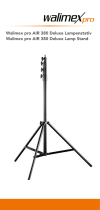
FW-806 Lampenstativ Air 280 cm
FW-806 Lamp Tripod Air 280 cm
By purchasing this product you have acquired a high-quality, versatile and
practice-oriented lamp stand / studio stand with long-term quality. The FW-806
oers a high level of comfort and additional safety thanks to its air-damped
elements, which enable slow and gentle lowering even under load. The lamp stand
is easy and uncomplicated to operate and very easy to transport due to its low
weight of only 1,8 kg. It has good stability in its light stand class and with a maxi-
mum load capacity of 6 kg and a height of 99 to 280 cm it has enough reserves
for your equipment.
We hope you enjoy using our product.
Your team from WALSER
Adjusting of the light stand
Loose the locking screw of the light stand angle adjustment (5). Pull the stand legs
(8) outwards and press the stand star (6) downwards. This spreads the legs. Set
the desired angle of the legs. Fix the legs by tightening the locking screw of the
light stand angle adjustment (5) again. Note that the base of the telescopic center
column (10) should not touch the ground as this will aect the stability of the stand.
Proceed when folding the stand in the reverse order.
WARNING!
Risk of squeezing ngers with the struts of the tripod legs (7).
Height adjustment
The light stand is equipped with a telescopic center column that can be extended.
The locking clamps of the center column (3) are xed by the locking fastener clips
(4). To adjust the height of the light stand, loosen the locking fastener clips (4). Set
the desired height and tighten the locking fastener clips (4) again. Press the center
column elements down to check that all locks are xed correctly. The stand is now
ready to use.
Installation of equipment on the light stand
Using the adapter on the top, you can attach devices such as studio ashes,
LED lights, softboxes, poles etc. to this stand. Loosen the mounting screw of the
bracket. Insert the holder of your device from above into the tripod adapter (1) and
x the holder screw.
On the upper end of the mounting adapter (1) a 1/4 inch thread can be used. You
can also attach suitable equipment here.
A further adapter from 1/4 to 3/8 inch (11) is included with this stand. You can also
attach suitable equipment here with the 3/8 inch thread.
Recommended accessories for increased stability
When using heavy equipment with large extension height, we recommend ad-
ditional accessories for stabilization. For this we recommend the use of special
sandbags or weights.
You will nd suitable accessory articles in our webshop www.foto-walser.de
Art.-No. / Name
• 15537 walimex pro sand bag
• 15876 walimex stand weight 3 kg
• 13739 walimex weight for rods and boom stands 4,4 kg
Usage notes and maintenance of the light stand
• Note that light stands generally must be placed on a suciently strong, level
surface to ensure maximum stability and to allow the maximum load capacity.
• Note the maximum load capacity of your light stand model (see technical data).
• Note the max. load values specied for centrally placed equipment on the
stand.
• Regular removal of sand, dust and other contaminants is recommended.
If you notice a scratching or crunching sound when moving the center column
segments, remove the impurities with a soft, damp cloth.
• Hold the center column segment with one hand during the release of the locks
before you loosen one adjustment clamp.
• Do not move a stand with mounted equipment and extended center column.
There is a strong leverage eect with a combination of heavy equipment and
a large center column extension.
Technical specications
walimex pro FW-806 Lamp Tripod Air 280 cm
Article No. 16316
Stand type Light stand
Max. working height 280 cm
Min. working height 99 cm
Min. packing size 99,5 cm
Max. load capacity 6 kg
Weight 1,8 kg
No. Segments center column 3
No. Segments center column extendable 2
Type stand locks Lever clips
Ø Tubes stand segments 35, 30, 26 mm
Ø Max. footprint 110 cm
Connection adapter 1/4" thread,
5/8" Spigot
Additionally connection adapter included 3/8“ thread adapter
Stand tubes Aluminium
Locking clamps Plastic
Stand locking clips Metal, Plastic
Scope of delivery
1 x walimex pro FW-806 Light stand, 1 x adapter 1/4 to 3/8 inch,
1 x Carrying bag, 1 x Manual D / EN
Notes:
Niclas Walser
Founder and Owner
WALSER GmbH & Co. KG
Senefelderstrasse 23
86368 Gersthofen
Germany
info@walser.de
www.walser.de
Made in China
D
Wir freuen uns, dass Sie sich für ein walimex pro Produkt aus dem Hause WALSER
entschieden haben und wünschen Ihnen viel Freude mit unserem Produkt.
WALSER bietet seinen Kunden mit den Marken walimex pro und Mantona preis-
werte, ausgewählte und exklusive Produkte für kreative Foto- und Videograe
direkt vom Her steller.
Dabei protieren sowohl ambitionierte Anfänger wie auch Pros von unserem
Produkt-Know-how und einem ausgezeichneten Service. Ob Fragen zu tech-
nischen Details oder zu Einsatzgebieten unserer Produkte – mit einer indivi-
duellen Fachberatung durch ausgebildete Fotografen unterstützen wir unsere
Kunden auch nach dem Kauf in allen Aspekten rund um unser Portfolio.
Teilen Sie unsere Begeisterung für professionelle Foto- und Videograe und lassen
auch Sie sich von unseren Produkten inspirieren!
Ihr Team von WALSER
EN
We are pleased that you have chosen a walimex pro product from WALSER
and wish you lots of pleasure with our product.
With the brands walimex pro and Mantona, WALSER oers its customers inex-
pensive, selected and exclusive products for creative photography and video-
graphy directly from the manufacturer.
Both ambitious beginners and professionals benet from our product know-how
and excellent service. Whether you have questions about technical details or
areas of application for our products - with individual expert advice from trained
photo graphers, we support our customers in all aspects of our portfolio even
after the purchase.
Share our enthusiasm for profes sional photography and videography and let
yourself be inspired by our products!
Your team from WALSER

1
5
2
7
8
6
10
9
Wir freuen uns, dass Sie sich für ein
walimex pro
Produkt aus dem Hause WALSER
entschieden haben.
Mit dem Kauf dieses Produktes haben Sie ein kompaktes und für seine Größe leichtes
Lampen- / Licht- / Studiostativ erworben. Durch seine luftgedämpften Elemente,
die ein langsames und sanftes Absenken auch unter Last ermöglichen, bietet das
FW-806 einen hohen Bedienkomfort und zusätzliche Sicherheit. Es ist einfach und
unkompliziert bedienbar und durch das geringe Gewicht von nur 1,8 kg sehr einfach
zu transportieren. Es verfügt in seiner Stativklasse über eine gute Stabilität und
besitzt mit einer maximalen Belastbarkeit von 6 kg sowie einer Höhe von 99 bis
280 cm genug Reserven für ihr Equipment.
Wir wünschen Ihnen viel Freude mit unserem Produkt.
Ihr Team von WALSER
Aufbau des Statives
Lösen Sie die Feststellschraube der Stativbein-Verriegelung zur Winkeleinstellung
(5). Ziehen Sie die Stativbeine (8) nach außen und drücken Sie den Stativstern
(6) nach unten. Hierdurch werden die Stativbeine gespreizt. Stellen Sie den ge-
wünschten Winkel der Stativbeine ein. Für eine optimale Standfestigkeit empfeh-
len wir eine breite Spreizung der Stativbeine. Fixieren Sie die Stativbeine durch
das Festziehen der Stativbein-Verriegelungsschraube (5). Beachten Sie, dass die
Basis der Teleskopmittelsäule (10) nicht den Boden berühren sollte, dies beein-
trächtigt die Stabilität des Statives.
Verfahren Sie beim Zusammenlegen des Statives in umgekehrter Reihenfolge
ACHTUNG! Klemmgefahr für Finger durch die Streben der Stativbeine (7)
Höhenverstellung
Das Stativ verfügt über eine mehrteilige, ausziehbare Teleskopmittelsäule.
Mithilfe der Verriegelungsclips der Stativverschlüsse (4) werden die Verschlussklem-
men der Mittelsäule (3) arretiert. Lösen Sie zur Höheneinstellung des Statives die
Stativverschluss Clips (4). Stellen Sie die gewünschte Höhe ein und verschlie-
ßen Sie die Clips wieder. Kontrollieren Sie abschließend durch ein Drücken der
Mittelsäulenelemente nach unten, ob sämtliche Verschlüsse korrekt xiert sind.
Das Stativ ist jetzt einsatzbereit.
Montage von Equipment auf dem Stativ
Am oberen Ende der Mittelsäule bendet sich ein Befestigungsadapter (1). Dieser
verfügt über einen als 16mm Zapfen oder auch 5/8 Zoll Spigot bekannten An-
schluss. Mithilfe dieses Adapters lassen sich Geräte wie Studioblitze, Leuchten,
Softboxen, Polestangen uvm. per genormter Halterung befestigen.
Schrauben Sie zur Befestigung Ihres Equipments die Arretierungsschraube der
Gerätehaltung Ihres zu befestigenden Zubehörs etwas heraus und führen Sie die
Gerätehalterung Ihres Equipments von oben in den Stativadapter (1) ein.
Ziehen Sie anschließend die Schraube wieder fest an. Achten Sie hierbei auf die
korrekte Positionierung der Halterung. Die Schraube muss am dünneren Teil des
Befestigungsadapters (1) festgeschraubt werden. Hierdurch wird ein Lösen der
Halterung inkl. Ihres Equipments zuverlässig verhindert.
Auf dem oberen Ende des
Befestigungsadapters (1) ist zusätzlich ein 1/4 Zoll Anschlußgewinde nutzbar. Auch
hieran können Sie passendes Equipment befestigen.
Im Lieferumfang dieses Statives ist zusätzlich eine weitere Adapterhülse (11) ent-
halten. Diese verfügt über einen 3/8 Zoll Gewindeanschluß und ermöglicht somit
auch die Befestigung von Equipment mit diesem Anschlussformat.
Empfehlenswertes Zubehör zur Erhöhung der Standfestigkeit
Beim Einsatz von schwerem Equipment, vor allem in Kombination mit einer gro-
ßen Auszugshöhe, kann es notwendig sein, die Standfestigkeit des Statives durch
zusätzliche Beschwerungsmaßnahmen zu erhöhen. Hierfür empfehlen wir die Ver-
wendung von speziellen Sandsäcken oder Stativgewichten. Diese gewährleisten
auch bei widrigen Bedingungen die optimale Standfestigkeit Ihres Statives.
Passende Zubehörartikel nden Sie in unserem Webshop www.foto-walser.de unter:
Artikelnummer, Bezeichnung
•
15537 walimex pro Sandsack
•
15876 walimex Stativgewicht, 3 kg
•
13739 walimex Gewicht für Stangen & Galgenstative, 4,4 kg
Benutzungshinweise und Pege des Statives
• Beachten Sie, dass Lampenstative auf einem ausreichend belastbaren, ebenen
Untergrund aufgestellt werden müssen, um eine maximale Stabilität und Traglast
zu gewährleisten.
• Beachten Sie die Hinweise bzgl. der maximalen Belastbarkeit Ihres Stativmodells
(siehe Technische Daten).
• Berücksichtigen Sie, dass die angegebenen Belastungswerte für zentral auf dem
Stativ platziertes Equipment gelten. Je nach verwendetem Equipment (und der
auftretenden Hebelwirkung) können die maximalen Belastungswerte vom ange-
gebenen Höchstwert abweichen.
• Beachten Sie, dass Feuchtigkeit an den Mittelsäulenelementen die Haltekraft
deutlich reduziert und die Mittelsäulensegmente bei Belastung dementsprechend
nach unten sinken können. Trocknen Sie daher ggf. die Mittelsäulenelemente mit
einem weichen, saugfähigen Tuch (z.B. aus Baumwolle).
• Generell sind alle Elemente dieses Lampenstatives wartungsfrei. Allerdings ist
das regelmäßige Entfernen von Sand, Staub und anderen Verunreinigungen zu
empfehlen. Wenn Sie ein kratzendes oder knirschendes Geräusch beim Bewegen
der Mittelsäulensegmente feststellen, entfernen Sie bitte mit einem weichen,
angefeuchteten Tuch die Verunreinigungen.
• Achten Sie beim Verstellen der Mittelsäule mit montiertem Equipment zu Ihrer
eigenen Sicherheit und zum Schutz des verbauten Equipments darauf, dass Sie
während des Lösens der Verschlüsse gleichzeitig das entsprechende Mittelseg-
ment mit einer Hand festhalten, bevor Sie die Stativverschlüsse lockern.
• Beachten Sie bei der Befestigung von Equipment per 1/4 Zoll Gewinde, dass
diese über eine geringere Belastbarkeit verfügen als der 16 mm Zapfen (5/8
Zoll Spigot) Anschluss. Für die Befestigung von schwerem Equipment ist eine
entsprechend hochwertige Halterung notwendig.
• Bewegen Sie ein bestücktes Stativ mit ausgezogener Mittelsäule nicht oder nur
sehr vorsichtig und ach über dem Boden. Es ergibt sich häug eine unerwartet
starke und sehr plötzlich auftretende Hebelwirkung bei schwerem Equipment in
Kombination mit einem großen Mittelsäulenauszug. Durch die konstruktionsbe-
dingte Kopastigkeit eines Lampenstatives mit verbautem Equipment kann das
Stativ blitzschnell kippen und das befestigte Gerät kann beschädigt werden und/
oder den Bediener verletzen.
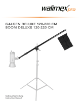
A) Bauteile Stativ
1 Befestigungsadapter
2 Teleskopmittelsäulen-Rohre
3 Verschlussklemmen
4 Verriegelungsclip Stativverschlüsse
5 Feststellschraube Verriegelung
Stativbein Winkeleinstellung
6 Stativstern
7 Streben der Stativbeine
8 Stativbeine
9 Stativbeinfüße mit Gummistopfen
10 Mittelsäulen Basis
11 Adapterhülse 1/4 Zoll auf
3/8 Zoll Gewinde
A) Components light stand
1 Spigot adapter
2 Telescope center column tubes
3 Locking clamp
4 Locking fastener clips
5 Locking screw light stand angle
adjustment
6 Stand star/shoulder
7 Leg struts
8 Stand legs
9 Stand leg feet with rubber stoppers
10 Telescope center column base
11 Adapter 1/4 inch to 3/8 inch thread
Technische Daten
walimex pro FW-806 Lampenstativ Air 280 cm
Artikelnummer 16316
Stativtyp Lampenstativ
Max. Arbeitshöhe 280 cm
Min. Arbeitshöhe 99 cm
Minimales Packmaß 99,5 cm
Max. Traglast Stativ 6 kg
Gewicht 1,8 kg
Anzahl Segmente Mittelsäule 3
Anzahl Segmente Mittelsäule ausziehbar 2
Typ Stativverschlüsse Hebel
Ø Stativsegment 35, 30, 26 mm
Ø Standäche max. 110 cm
Adapteranschluss 1/4" Gewinde,
5/8" Spigot
Zusätzlicher Adapter enthalten 3/8“ Gewinde Adapter
Stativrohre Aluminium
Verschlussklemmen Kunststo
Stativverschlüsse Metall, Kunststo
Lieferumfang
1 x walimex pro FW-806 Lampenstativ, 1 x Adapter 1/4 auf 3/8 Zoll,
1 x Transport- und Aufbewahrungstasche, 1 x Anleitung D / EN
Niclas Walser
Inhaber
GB I F D
1
7
8
9
2
3
4
EINFÜHRUNG
Das Manfrotto “NanoPole Stand” ist ein vielseitiges Stativ für den Gebrauch im Studio oder
an anderen Einsatzorten. Dank seiner Funktionen eröffnet es jedem Fotografen neue Mög-
lichkeiten und erleichtert gleichzeitig seinen Job.
Es ist gebaut, um Scheinwerfer bis 1,5 kg zu tragen. Dieses Stativ ist leicht und kompakt, um
eine maximale Transportierfähigkeit zu gewährleisten.
Im gemeinsamen Einsatz mit dem Manfrotto “Snap Tilthead” stellt es eine perfekte Lösung
für das Befestigen von Leuchten in verschiedenen Einsatzbereichen dar.
PRODUKTMERKMALE
• Leicht und kompakt, aber gleichzeitig sehr stabil.
• Schnell aufzubauen.
• Die Säule kann vom Fuß abmontiert werden. So kann die Säule einfach als tragbarer Arm
genutzt werden. (Patent angemeldet)
• Perfekt im Gebrauch an verschiedenen Einsatzorten, dank seines Hakens für Sandsäcke
und des Nivellierbeins.
TECHNISCHE MERKMALE
• Die Blockierhülsen der Säulenverlängerung sind aus Aluminiumdruckguss
• Maximale Beladung: 1,5 kg
• Aufsatz: 16 mm (5/8”) Schraube mit 3/8” oder 1/4” Gewinde
• Maximale Höhe: 1,95 m
• Maximale Höhe, wenn geschlossen: 49 cm
AUFSTELLEN
Leuchtenstative müssen immer auf einem ebenen Grund aufgestellt werden, der hinreichend
belastbar ist, um das Gewicht des Stativs samt der Beladung tragen zu können. Der Boden
sollte flach sein; andernfalls sollten Sie das verstellbare Stativbein nutzen, um die Säule auf
einer vertikalen Achse neu auszurichten
(Abb. 7)
.
ÖFFNEN DER STATIVBEINE
Lösen Sie die Feststellschraube “A”, drücken Sie die Fußhalterung “B” nach unten und
ziehen Sie die Stativbeine “C” nach außen.
Um eine maximale Stabilität zu erhalten, positionieren Sie die Beinverstrebung auf der Mar-
kierung “Max stability”, was auf der Säule geschrieben steht.
Fixieren Sie die Stativbeine durch Festziehen der Schraube “A”.
Die Stativsäule darf niemals den Boden berühren, da dies die Stabilität des Stativs
beeinträchtigen würde.
GEBRAUCH
&
Überschreiten Sie niemals die maximale Belastbarkeit (siehe Abschnitt “Technische Merkmale”).
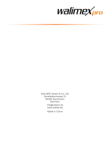
BELADUNG: Betrachten Sie für die Anleitung zur Beladung Abb. 2 und 3
Bei Verwendung von T-Trägern sollte das Gewicht der Beladung immer ausbalanciert werden
(Abb. 3).
HÖHENVERSTELLUNG
,
&
Das Stativ verfügt über eine ausziehbare Teleskopmittelsäule.
Es werden Blockierschrauben (Abb. 4) verwendet, um die Mittelsäule in der gewünschten
Höhe zu fixieren.
Überprüfen Sie, bevor Sie das Stativ beladen, durch nach unten drücken, ob die Mittelsäule
wirklich fest fixiert ist. Dies sollten Sie regelmäßig kontrollieren (Abb. 5).
Bitte achten Sie beim Tieferstellen jedes Teleskopauszugs zu Ihrer eigenen Sicherheit darauf,
dass Sie zuerst den entsprechenden Auszug mit einer Hand festhalten (Abb. 6), bevor Sie
die Blockierschraube lockern. Sie sollten kein beladenes Stativ mit ausgezogener Mittelsäule
bewegen.
GEBRAUCH DER SÄULEN ALS TRAGBARER ARM
Um die Säule vom Fuß des Stativs zu lösen, entriegeln Sie die Feststellschraube “A”, und drü -
cken Sie den Knopf “D”. Die Stange kann nun als tragbarer Arm benutzt werden, um die Leuch -
ten über das zu beleuchtende Objekt zu halten und es seitlich oder von oben zu beleuchten.
Auch in diesem Falle sollten Sie niemals die maximale Belastbarkeit überschreiten (lesen
Sie dazu den Abschnitt “Technische Merkmale”). Um das Stativ wieder zusammenzubauen,
stecken Sie die Stange wieder in die Fußhalterung und drücken Sie sie nach unten bis Sie ein
“Klick” hören. Die Markierung “E” auf der Säule muss mit der am Fuß übereinstimmen “F”.
ZUBEHÖR
SANDSACK(Art. G100-1)
Verwenden Sie Sandsäcke, um dem Stativ mehr Stabilität zu geben. Füllen Sie diese mit
Sand oder anderen Materialien und hängen Sie diese an den am Stativ vorgesehenen Haken
am oberen Gehäuse (fig. 9) auf.
Bevor Sie das Manfrotto NanoPole Stativ benutzen, lesen Sie sorgfältig das
beigefügte Dokument “Generelle Anweisungen und Warnungen”.
1
2 3
4 5 6
8
9
INTRODUCTION
Le «NanoPole» de Manfrotto est un pied polyvalent utilisable en extérieur et en studio.
Grâce à ses fonctionnalités, il offre au photographe de nouvelles possibilités tout en facili -
tant son travail.
léger et compact, pour garantir une facilité de transport maximale.
Utilisé en association avec la rotule inclinable «Snap» de Manfrotto, il constitue une
solution
idéale pour la fixation des flashs de type cobra dans différentes applications.
AVANTAGES DU PRODUIT
• Léger et compact, tout en étant très stable.
• Mise en place rapide
• La colonne peut être détachée de la base. Ainsi, elle peut être facilement utilisée comme
une perche. (Brevet en instance).
• Idéal pour un usage sur le terrain, grâce à son crochet pour sac de lestage et à la jambe
de mise à niveau.
CARACTÉRISTIQUES TECHNIQUES
• Les bagues d’extension de la colonne sont en aluminium moulé sous pression.
•
•
•
•
INSTALLATION
Les pieds d’éclairage doivent toujours être placés sur un sol stable, capable de supporter
le poids du pied et de l’équipement qui y est monté. Le sol doit être plat. Si ce n’est pas le
cas, utilisez la jambe de mise à niveau pour réaligner la colonne sur l’axe vertical (fig. 7).
COMMENT OUVRIR LA BASE
Débloquez la molette “A”, appuyez sur la fonderie supérieure “B” et étendez les jambes
“C” vers l’extérieur.
Pour une stabilité maximale, positionnez la fonderie supérieure sur l’indication «Max stabi -
lity» inscrite sur la colonne.
Verrouillez les jambes et la base en serrant la molette “A”.
La colonne centrale ne doit jamais toucher le sol, car cela pourrait déstabiliser le
pied.
INSTRUCTIONS D’UTILISATION et
Ne jamais dépasser la capacité de charge maximale (voir la section «Caractéristiques
techniques»).
CHARGEMENT : Voir les fig. 2 et 3 pour les instructions de chargement
Lors de l’utilisation d’une barre en T, les charges doivent être équilibrées (fig. 3).
AJUSTEMENT DE LA HAUTEUR , et
Le pied est doté d’une colonne centrale télescopique pour le réglage de la hauteur.
Les molettes de serrage (fig. 4) permettent de verrouiller la position des sections.
Assurez-vous que chaque section de la colonne est fermement verrouillée en appuyant sur
le pied avant de le charger. Ce réglage doit être vérifié régulièrement (fig. 5)
Pour votre sécurité, lorsque vous abaissez chaque section télescopique de la colonne,
soutenez fermement l’équipement chargé (fig. 6) en maintenant la section correspondante
d’une main, tout en desserrant la molette.
Il est recommandé de ne pas déplacer un pied dont la colonne est relevée, avec l’équipe -
ment chargé.
UTILISATION DE LA COLONNE COMME UNE PERCHE
Pour détacher la colonne de la base du pied, desserrez la molette “A”, puis appuyez sur le
bouton “D”. La perche peut maintenant être utilisée seule, tenue en mains pour maintenir
un équipement d’éclairage au-dessus du sujet et l’éclairer depuis le côté ou le dessus.
Dans ce cas également, ne jamais dépasser la capacité de charge maximale (voir la section
«Caractéristiques techniques»). Pour refixer la perche au pied, insérez la perche dans la
base et appuyez jusqu’à ce qu’un «clic» se fasse entendre. L’indication “E” sur la colonne
doit être alignée avec la fonderie inférieure“F”.
ACCESSOIRES
SAC DE LESTAGE (Art. G100-1)
similaire et accrochez-le au crochet prévu à cet effet, situé sur la fonderie supérieure du
pied (fig. 9).
Avant de commencer à utiliser le pied NanoPole de Manfrotto, lisez attentivement le
document «Instructions générales et avertissements» fourni.
1
2 3
4 5 6
8
9
INTRODUCTION
Manfrotto “NanoPole Stand” is a versatile stand for use on location and in studio; thanks to
its features, it brings new possibilities to the photographer, while making his job easier.
Designed to support luminaries up to 1,5Kg, this stand is lightweight and compact, to
guarantee maximum portability.
When used in combination with Manfrotto “Snap Tilthead”, it represents a perfect solution
for supporting flashguns in different applications.
PRODUCT BENEFITS
• Lightweight and compact, but at the same time very stable.
• Quick to set-up
• The column can be detached from the base. In this way, the column can be used easily
as a hand-held boom. (Patent pending)
• Perfect for use in location, thanks to the hook for sandbag and the levelling leg.
TECHNICAL FEATURES
• Column extension collars are pressure die cast aluminium
• Maximum payload: 1,5 kg
• Top attachment: 16 mm (5/8”) male top stud with 3/8” or 1/4” thread
• Maximum height :1,95 m
• Maximum height when closed: 49 cm
SET UP
Lighting stands must always be set-up on firm ground, capable of supporting the weight of
both the stand and the load. The ground should be flat; in case it’s not, use the levelling leg
to realign the column on vertical axis (fig. 7).
HOW TO OPEN THE BASE
Unlock knob “A”, press upper casting “B” down and spread the legs “C” outwards.
To obtain maximum stability, position the upper casting right on the indication “Max stabil -
ity”, which you can find written on the column.
Lock the legs and base by tightening the knob “A”.
The center column must never touch the ground as this adversely effects the
stability of the stand.
OPERATING INSTRUCTIONS &
Never exceed the maximum payload (see the section “Technical Features”)
LOADING: See fig. 2 and 3 for loading instructions
When using a T bar, loads should be balanced (fig. 3).
HEIGHT ADJUSTMENT , &
The stand has a telescopic centre column for height adjustment.
Locking knobs (fig. 4) are used to secure the risers in place.
Make sure that each riser of the column is locked tightly by applying pressure down, before
loading the stand. This should be checked regularly (fig. 5)
For your own safety, when lowering each telescopic section of the column, firmly support
the load (fig. 6) by holding the relevant section with one hand, whilst unlocking the knob.
It is recommended not to move stands with raised columns and applied load.
USE OF THE COLUMN AS HAND-HELD BOOM
To detach the column from the base of the stand, unlock the knob “A”, and then press the
button “D”. The pole can now be used as hand-held boom, to hold up lighting gear over
the subject and illuminate it from side or above.
Also in this case, never exceed the maximum payload (see the section “Technical Fea -
tures”). To reassemble the stand, insert the pole back into the base and press downwards
until you hear a “click”. The indication “E” on the column must be aligned with the lower
casting “F”.
ACCESSORIES
SAND BAG (Art. G100-1)
Designed to allow more stability: Fill bags with sand or other material and position hang it
on the suitable hook, provided on the stand upper casting (fig. 9).
Before start using Manfrotto NanoPole Stand, carefully read through the document
“General Instructions and Warnings”, which you find attached.
1
2 3
4 5 6
8
9
INTRODUZIONE
Manfrotto “NanoPole Stand” è un versatile stativo da usare in location e in studio. Grazie
alle sue caratteristiche, offre nuove possibilità al fotografo mentre gli facilita il lavoro.
Progettato per sostenere lampade e flash fino a 1,5Kg, questo stativo è leggero e compat -
to, garantendo così la massima trasportabilità.
Usato insieme alla testa Manfrotto “Snap Tilthead”, rappresenta una soluzione perfetta per
il supporto di flash in applicazioni di vario genere.
VANTAGGI DEL PRODOTTO
• Leggero e compatto, ma anche molto stabile.
• Veloce da montare
• La colonna può essere staccata dalla base. In questo modo, si può usare facilmente la
colonna come asta da tenere in mano. (Brevetto in corso)
• Perfetto per l’uso in location, grazie al gancio per borsa portasabbia e alla gamba
livellabile.
CARATTERISTICHE TECNICHE
• Manicotti di estensione della colonna in alluminio pressofuso
• Portata massima: 1,5 kg
• Attacco superiore: codolo maschio da 16 mm (5/8”) con filettatura da 3/8” o 1/4”
• Altezza massima: 1,95 m
• Altezza massima da chiuso: 49 cm
MONTAGGIO
Gli stativi per luci vanno sempre sistemati su un piano stabile, in grado di reggere il peso
dello stativo più il carico. La superficie deve essere piana; in caso contrario, usare la gamba
livellabile per riallineare la colonna sull’asse verticale (fig. 7).
COME APRIRE LA BASE
Sbloccare la manopola “A”, premere sulla crociera superiore “B” verso il basso e allargare
le gambe “C” verso l’esterno.
Per ottenere la massima stabilità, posizionare la crociera superiore sull’indicazione “Max
stability”, riportata sulla colonna.
Bloccare le gambe e la base chiudendo la manopola “A”.
La colonna centrale non deve mai toccare il suolo, poiché questo compromettereb -
be la stabilità dello stativo.
ISTRUZIONI PER L’USO E
Non superare mai la portata massima (verificare le “Caratteristiche tecniche”)
CARICO: Vedere fig. 2 e 3 per le istruzioni sull’applicazione del carico
Usando una barra a T, i carichi devono risultare bilanciati (fig. 3).
REGOLAZIONE DELL’ALTEZZA , E
Lo stativo dispone di colonna centrale telescopica per la regolazione dell’altezza.
Le manopole di bloccaggio (fig. 4) permettono di fermare i montanti nelle posizioni deside -
rate.
Prima di applicare il carico sullo stativo, accertarsi che ciascun montante della colonna sia
ben fermo applicando un’adeguata pressione verso il basso. Questa verifica va ripetuta
regolarmente (fig. 5)
Per la vostra sicurezza, nell’abbassare ciascuna sezione telescopica della colonna occorre
sostenere il carico (fig. 6) tenendo con una mano la relativa sezione mentre si sblocca la
manopola.
Si raccomanda di non spostare gli stativi con le colonne sollevate e i carichi applicati.
USO DELLA COLONNA COME ASTA
Per staccare la colonna dalla base dello stativo, sbloccare la manopola “A”, quindi premere
il pulsante “D”. Ora l’asta si può usare come supporto da tenere in mano, avvicinando
lampade e flash al soggetto per illuminarlo da sopra o dal lato.
Anche in questo caso, non superare mai la portata massima (verificare alla sezione “Ca-
ratteristiche tecniche”). Per riassemblare lo stativo, reinserire l’asta nella base e premere
verso il basso fino a sentire uno “scatto”. L’indicazione “E” sulla colonna va allineata con la
crociera inferiore “F”.
ACCESSORI
BORSA PORTASABBIA (Art. G100-1)
Progettata per aumentare la stabilità: Riempire la borsa con sabbia o altro materiale e
appenderla al gancio predisposto sulla crociera superiore dello stativo (fig. 9).
Prima di iniziare ad usare lo stativo Manfrotto NanoPole, leggere con attenzione il
documento “Istruzioni e avvertenze generali”, che trovate allegato.
1
2 3
4 5 6
8
9
MAX
1,5 kg
3/8”
1/4”
5 6
1
2
2
2
3
3
A
A
F
E
D
C
E
F
B1
1
PATENT
PENDING
GB I F D
1
7
8
9
2
3
4
EINFÜHRUNG
Das Manfrotto “NanoPole Stand” ist ein vielseitiges Stativ für den Gebrauch im Studio oder
an anderen Einsatzorten. Dank seiner Funktionen eröffnet es jedem Fotografen neue Mög-
lichkeiten und erleichtert gleichzeitig seinen Job.
Es ist gebaut, um Scheinwerfer bis 1,5 kg zu tragen. Dieses Stativ ist leicht und kompakt, um
eine maximale Transportierfähigkeit zu gewährleisten.
Im gemeinsamen Einsatz mit dem Manfrotto “Snap Tilthead” stellt es eine perfekte Lösung
für das Befestigen von Leuchten in verschiedenen Einsatzbereichen dar.
PRODUKTMERKMALE
• Leicht und kompakt, aber gleichzeitig sehr stabil.
• Schnell aufzubauen.
• Die Säule kann vom Fuß abmontiert werden. So kann die Säule einfach als tragbarer Arm
genutzt werden. (Patent angemeldet)
• Perfekt im Gebrauch an verschiedenen Einsatzorten, dank seines Hakens für Sandsäcke
und des Nivellierbeins.
TECHNISCHE MERKMALE
• Die Blockierhülsen der Säulenverlängerung sind aus Aluminiumdruckguss
• Maximale Beladung: 1,5 kg
• Aufsatz: 16 mm (5/8”) Schraube mit 3/8” oder 1/4” Gewinde
• Maximale Höhe: 1,95 m
• Maximale Höhe, wenn geschlossen: 49 cm
AUFSTELLEN
Leuchtenstative müssen immer auf einem ebenen Grund aufgestellt werden, der hinreichend
belastbar ist, um das Gewicht des Stativs samt der Beladung tragen zu können. Der Boden
sollte flach sein; andernfalls sollten Sie das verstellbare Stativbein nutzen, um die Säule auf
einer vertikalen Achse neu auszurichten
(Abb. 7)
.
ÖFFNEN DER STATIVBEINE
Lösen Sie die Feststellschraube “A”, drücken Sie die Fußhalterung “B” nach unten und
ziehen Sie die Stativbeine “C” nach außen.
Um eine maximale Stabilität zu erhalten, positionieren Sie die Beinverstrebung auf der Mar-
kierung “Max stability”, was auf der Säule geschrieben steht.
Fixieren Sie die Stativbeine durch Festziehen der Schraube “A”.
Die Stativsäule darf niemals den Boden berühren, da dies die Stabilität des Stativs
beeinträchtigen würde.
GEBRAUCH
&
Überschreiten Sie niemals die maximale Belastbarkeit (siehe Abschnitt “Technische Merkmale”).
BELADUNG: Betrachten Sie für die Anleitung zur Beladung Abb. 2 und 3
Bei Verwendung von T-Trägern sollte das Gewicht der Beladung immer ausbalanciert werden
(Abb. 3).
HÖHENVERSTELLUNG
,
&
Das Stativ verfügt über eine ausziehbare Teleskopmittelsäule.
Es werden Blockierschrauben (Abb. 4) verwendet, um die Mittelsäule in der gewünschten
Höhe zu fixieren.
Überprüfen Sie, bevor Sie das Stativ beladen, durch nach unten drücken, ob die Mittelsäule
wirklich fest fixiert ist. Dies sollten Sie regelmäßig kontrollieren (Abb. 5).
Bitte achten Sie beim Tieferstellen jedes Teleskopauszugs zu Ihrer eigenen Sicherheit darauf,
dass Sie zuerst den entsprechenden Auszug mit einer Hand festhalten (Abb. 6), bevor Sie
die Blockierschraube lockern. Sie sollten kein beladenes Stativ mit ausgezogener Mittelsäule
bewegen.
GEBRAUCH DER SÄULEN ALS TRAGBARER ARM
Um die Säule vom Fuß des Stativs zu lösen, entriegeln Sie die Feststellschraube “A”, und drü -
cken Sie den Knopf “D”. Die Stange kann nun als tragbarer Arm benutzt werden, um die Leuch -
ten über das zu beleuchtende Objekt zu halten und es seitlich oder von oben zu beleuchten.
Auch in diesem Falle sollten Sie niemals die maximale Belastbarkeit überschreiten (lesen
Sie dazu den Abschnitt “Technische Merkmale”). Um das Stativ wieder zusammenzubauen,
stecken Sie die Stange wieder in die Fußhalterung und drücken Sie sie nach unten bis Sie ein
“Klick” hören. Die Markierung “E” auf der Säule muss mit der am Fuß übereinstimmen “F”.
ZUBEHÖR
SANDSACK(Art. G100-1)
Verwenden Sie Sandsäcke, um dem Stativ mehr Stabilität zu geben. Füllen Sie diese mit
Sand oder anderen Materialien und hängen Sie diese an den am Stativ vorgesehenen Haken
am oberen Gehäuse (fig. 9) auf.
Bevor Sie das Manfrotto NanoPole Stativ benutzen, lesen Sie sorgfältig das
beigefügte Dokument “Generelle Anweisungen und Warnungen”.
1
2 3
4 5 6
8
9
INTRODUCTION
Le «NanoPole» de Manfrotto est un pied polyvalent utilisable en extérieur et en studio.
Grâce à ses fonctionnalités, il offre au photographe de nouvelles possibilités tout en facili -
tant son travail.
léger et compact, pour garantir une facilité de transport maximale.
Utilisé en association avec la rotule inclinable «Snap» de Manfrotto, il constitue une
solution
idéale pour la fixation des flashs de type cobra dans différentes applications.
AVANTAGES DU PRODUIT
• Léger et compact, tout en étant très stable.
• Mise en place rapide
• La colonne peut être détachée de la base. Ainsi, elle peut être facilement utilisée comme
une perche. (Brevet en instance).
• Idéal pour un usage sur le terrain, grâce à son crochet pour sac de lestage et à la jambe
de mise à niveau.
CARACTÉRISTIQUES TECHNIQUES
• Les bagues d’extension de la colonne sont en aluminium moulé sous pression.
•
•
•
•
INSTALLATION
Les pieds d’éclairage doivent toujours être placés sur un sol stable, capable de supporter
le poids du pied et de l’équipement qui y est monté. Le sol doit être plat. Si ce n’est pas le
cas, utilisez la jambe de mise à niveau pour réaligner la colonne sur l’axe vertical (fig. 7).
COMMENT OUVRIR LA BASE
Débloquez la molette “A”, appuyez sur la fonderie supérieure “B” et étendez les jambes
“C” vers l’extérieur.
Pour une stabilité maximale, positionnez la fonderie supérieure sur l’indication «Max stabi -
lity» inscrite sur la colonne.
Verrouillez les jambes et la base en serrant la molette “A”.
La colonne centrale ne doit jamais toucher le sol, car cela pourrait déstabiliser le
pied.
INSTRUCTIONS D’UTILISATION et
Ne jamais dépasser la capacité de charge maximale (voir la section «Caractéristiques
techniques»).
CHARGEMENT : Voir les fig. 2 et 3 pour les instructions de chargement
Lors de l’utilisation d’une barre en T, les charges doivent être équilibrées (fig. 3).
AJUSTEMENT DE LA HAUTEUR , et
Le pied est doté d’une colonne centrale télescopique pour le réglage de la hauteur.
Les molettes de serrage (fig. 4) permettent de verrouiller la position des sections.
Assurez-vous que chaque section de la colonne est fermement verrouillée en appuyant sur
le pied avant de le charger. Ce réglage doit être vérifié régulièrement (fig. 5)
Pour votre sécurité, lorsque vous abaissez chaque section télescopique de la colonne,
soutenez fermement l’équipement chargé (fig. 6) en maintenant la section correspondante
d’une main, tout en desserrant la molette.
Il est recommandé de ne pas déplacer un pied dont la colonne est relevée, avec l’équipe -
ment chargé.
UTILISATION DE LA COLONNE COMME UNE PERCHE
Pour détacher la colonne de la base du pied, desserrez la molette “A”, puis appuyez sur le
bouton “D”. La perche peut maintenant être utilisée seule, tenue en mains pour maintenir
un équipement d’éclairage au-dessus du sujet et l’éclairer depuis le côté ou le dessus.
Dans ce cas également, ne jamais dépasser la capacité de charge maximale (voir la section
«Caractéristiques techniques»). Pour refixer la perche au pied, insérez la perche dans la
base et appuyez jusqu’à ce qu’un «clic» se fasse entendre. L’indication “E” sur la colonne
doit être alignée avec la fonderie inférieure“F”.
ACCESSOIRES
SAC DE LESTAGE (Art. G100-1)
similaire et accrochez-le au crochet prévu à cet effet, situé sur la fonderie supérieure du
pied (fig. 9).
Avant de commencer à utiliser le pied NanoPole de Manfrotto, lisez attentivement le
document «Instructions générales et avertissements» fourni.
1
2 3
4 5 6
8
9
INTRODUCTION
Manfrotto “NanoPole Stand” is a versatile stand for use on location and in studio; thanks to
its features, it brings new possibilities to the photographer, while making his job easier.
Designed to support luminaries up to 1,5Kg, this stand is lightweight and compact, to
guarantee maximum portability.
When used in combination with Manfrotto “Snap Tilthead”, it represents a perfect solution
for supporting flashguns in different applications.
PRODUCT BENEFITS
• Lightweight and compact, but at the same time very stable.
• Quick to set-up
• The column can be detached from the base. In this way, the column can be used easily
as a hand-held boom. (Patent pending)
• Perfect for use in location, thanks to the hook for sandbag and the levelling leg.
TECHNICAL FEATURES
• Column extension collars are pressure die cast aluminium
• Maximum payload: 1,5 kg
• Top attachment: 16 mm (5/8”) male top stud with 3/8” or 1/4” thread
• Maximum height :1,95 m
• Maximum height when closed: 49 cm
SET UP
Lighting stands must always be set-up on firm ground, capable of supporting the weight of
both the stand and the load. The ground should be flat; in case it’s not, use the levelling leg
to realign the column on vertical axis (fig. 7).
HOW TO OPEN THE BASE
Unlock knob “A”, press upper casting “B” down and spread the legs “C” outwards.
To obtain maximum stability, position the upper casting right on the indication “Max stabil -
ity”, which you can find written on the column.
Lock the legs and base by tightening the knob “A”.
The center column must never touch the ground as this adversely effects the
stability of the stand.
OPERATING INSTRUCTIONS &
Never exceed the maximum payload (see the section “Technical Features”)
LOADING: See fig. 2 and 3 for loading instructions
When using a T bar, loads should be balanced (fig. 3).
HEIGHT ADJUSTMENT , &
The stand has a telescopic centre column for height adjustment.
Locking knobs (fig. 4) are used to secure the risers in place.
Make sure that each riser of the column is locked tightly by applying pressure down, before
loading the stand. This should be checked regularly (fig. 5)
For your own safety, when lowering each telescopic section of the column, firmly support
the load (fig. 6) by holding the relevant section with one hand, whilst unlocking the knob.
It is recommended not to move stands with raised columns and applied load.
USE OF THE COLUMN AS HAND-HELD BOOM
To detach the column from the base of the stand, unlock the knob “A”, and then press the
button “D”. The pole can now be used as hand-held boom, to hold up lighting gear over
the subject and illuminate it from side or above.
Also in this case, never exceed the maximum payload (see the section “Technical Fea -
tures”). To reassemble the stand, insert the pole back into the base and press downwards
until you hear a “click”. The indication “E” on the column must be aligned with the lower
casting “F”.
ACCESSORIES
SAND BAG (Art. G100-1)
Designed to allow more stability: Fill bags with sand or other material and position hang it
on the suitable hook, provided on the stand upper casting (fig. 9).
Before start using Manfrotto NanoPole Stand, carefully read through the document
“General Instructions and Warnings”, which you find attached.
1
2 3
4 5 6
8
9
INTRODUZIONE
Manfrotto “NanoPole Stand” è un versatile stativo da usare in location e in studio. Grazie
alle sue caratteristiche, offre nuove possibilità al fotografo mentre gli facilita il lavoro.
Progettato per sostenere lampade e flash fino a 1,5Kg, questo stativo è leggero e compat -
to, garantendo così la massima trasportabilità.
Usato insieme alla testa Manfrotto “Snap Tilthead”, rappresenta una soluzione perfetta per
il supporto di flash in applicazioni di vario genere.
VANTAGGI DEL PRODOTTO
• Leggero e compatto, ma anche molto stabile.
• Veloce da montare
• La colonna può essere staccata dalla base. In questo modo, si può usare facilmente la
colonna come asta da tenere in mano. (Brevetto in corso)
• Perfetto per l’uso in location, grazie al gancio per borsa portasabbia e alla gamba
livellabile.
CARATTERISTICHE TECNICHE
• Manicotti di estensione della colonna in alluminio pressofuso
• Portata massima: 1,5 kg
• Attacco superiore: codolo maschio da 16 mm (5/8”) con filettatura da 3/8” o 1/4”
• Altezza massima: 1,95 m
• Altezza massima da chiuso: 49 cm
MONTAGGIO
Gli stativi per luci vanno sempre sistemati su un piano stabile, in grado di reggere il peso
dello stativo più il carico. La superficie deve essere piana; in caso contrario, usare la gamba
livellabile per riallineare la colonna sull’asse verticale (fig. 7).
COME APRIRE LA BASE
Sbloccare la manopola “A”, premere sulla crociera superiore “B” verso il basso e allargare
le gambe “C” verso l’esterno.
Per ottenere la massima stabilità, posizionare la crociera superiore sull’indicazione “Max
stability”, riportata sulla colonna.
Bloccare le gambe e la base chiudendo la manopola “A”.
La colonna centrale non deve mai toccare il suolo, poiché questo compromettereb -
be la stabilità dello stativo.
ISTRUZIONI PER L’USO E
Non superare mai la portata massima (verificare le “Caratteristiche tecniche”)
CARICO: Vedere fig. 2 e 3 per le istruzioni sull’applicazione del carico
Usando una barra a T, i carichi devono risultare bilanciati (fig. 3).
REGOLAZIONE DELL’ALTEZZA , E
Lo stativo dispone di colonna centrale telescopica per la regolazione dell’altezza.
Le manopole di bloccaggio (fig. 4) permettono di fermare i montanti nelle posizioni deside -
rate.
Prima di applicare il carico sullo stativo, accertarsi che ciascun montante della colonna sia
ben fermo applicando un’adeguata pressione verso il basso. Questa verifica va ripetuta
regolarmente (fig. 5)
Per la vostra sicurezza, nell’abbassare ciascuna sezione telescopica della colonna occorre
sostenere il carico (fig. 6) tenendo con una mano la relativa sezione mentre si sblocca la
manopola.
Si raccomanda di non spostare gli stativi con le colonne sollevate e i carichi applicati.
USO DELLA COLONNA COME ASTA
Per staccare la colonna dalla base dello stativo, sbloccare la manopola “A”, quindi premere
il pulsante “D”. Ora l’asta si può usare come supporto da tenere in mano, avvicinando
lampade e flash al soggetto per illuminarlo da sopra o dal lato.
Anche in questo caso, non superare mai la portata massima (verificare alla sezione “Ca-
ratteristiche tecniche”). Per riassemblare lo stativo, reinserire l’asta nella base e premere
verso il basso fino a sentire uno “scatto”. L’indicazione “E” sulla colonna va allineata con la
crociera inferiore “F”.
ACCESSORI
BORSA PORTASABBIA (Art. G100-1)
Progettata per aumentare la stabilità: Riempire la borsa con sabbia o altro materiale e
appenderla al gancio predisposto sulla crociera superiore dello stativo (fig. 9).
Prima di iniziare ad usare lo stativo Manfrotto NanoPole, leggere con attenzione il
documento “Istruzioni e avvertenze generali”, che trovate allegato.
1
2 3
4 5 6
8
9
MAX
1,5 kg
3/8”
1/4”
5 6
1
2
2
2
3
3
A
A
F
E
D
C
E
F
B1
1
PATENT
PENDING
1
34
Notizen:
Wir sind für Sie da!
Sollten Sie Hilfe oder eine kostenfreie, individuelle Beratung durch unser geschul-
tes Fachpersonal benötigen, dann freuen wir uns, wenn Sie mit unserem Service-
team Kontakt aufnehmen.
Wir helfen Ihnen gerne!
Ihr Team von WALSER
E-Mail / Homepage
info@walser.de
www.walser.de
Unsere Postanschrift:
WALSER GmbH & Co. KG
Senefelderstrasse 23
86368 Gersthofen
Deutschland
Unser Garantieversprechen
WALSER ist bekannt für seine hochwertige Verarbeitung, beste Funktionalität
und einen kundennahen Service. Um unserem außergewöhnlichen Serviceni-
veau zusätzlichen Ausdruck zu verleihen, geben wir für dieses walimex pro
Produkt eine Garantie von 2 Jahren. Diese Garantie ist nur in Verbindung mit
Ihrem Kaufbeleg gültig.
Wenn Sie unsere Garantie in Anspruch nehmen wollen, kontaktieren Sie uns bitte
per Mail unter info@foto-walser.de.
Unser umfassendes Garantieversprechen und den Garantieumfang nden Sie
unter www.foto-walser.de/garantie
11
1/2