
EN
DE
FR
IT
NL
SV
FI
INSTRUCTIONS FOR INSTALLATION AND USE
English
Version 09/23 ID no. 1-041-284
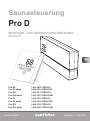
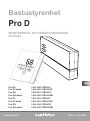
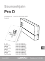
Sauna control unit
Pro D
Pro D2 1-041-288 / PRO-D2
Pro D2 white 1-041-290 / PRO-D2W
D2i 1-041-291 / PRO-D2I
Pro D2i white 1-041-292 / PRO-D2IW
Pro D3 1-041-293 / PRO-D3
Pro D3 white 1-041-294 / PRO-D3W
Pro D3i 1-041-295 / PRO-D3I
Pro D3i white 1-041-296 / PRO-D3IW

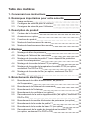
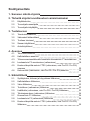
Table of Contents
1. About this instruction manual 5
2. Important information for your safety 6
2.1. Intended use 6
2.2. Safety information for the installer 7
2.3. Safety information for the user 8
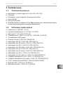
3. Product description 9
3.1. Scope of delivery 9
3.2. Optional accessories 9
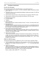
3.3. Product features 10
3.4. Sauna operating modes 12
3.5. Sensor operating modes 12
4. Installation 14
4.1. Installing the power supply unit 14
4.2. Installing the control panel 16
4.3. Installing the heater sensor F1 with overheat cut-out 19
4.4. Installing the bench sensor F2 (optional) 19
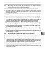
4.5. Installing humidity/temperature sensor FTS2 (optional, Pro D3 / Pro
D3i only) 20
4.6. Installing foil sensor FTS2 (optional, Pro D2i / Pro D3i only) 20
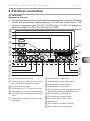
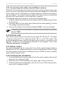
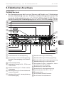
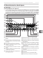
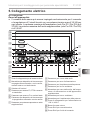
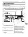
5. Electrical connection 21
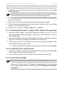
5.1. Connecting the power supply cable, heater and vaporizer 22
5.2. Connecting the control panel 22
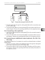
5.3. Connecting the light 22
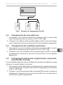
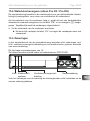
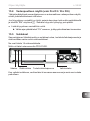
5.4. Connecting a fan (optional) 23
5.5. Connecting an additional output (optional, Pro D2i / Pro D3i only) 23
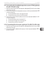
5.6. Connecting the power booster (optional) 24
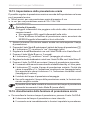
5.7. Connecting the heater sensor F1 24
5.8. Installing bench sensor F2 (optional) 24
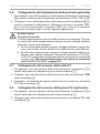
5.9. Connecting the humidity/temperature sensor FTS2
(optional, Pro D3 / Pro D3i only) 25
5.10. Connecting the foil sensor (optional, Pro D2i / Pro D3i only) 25
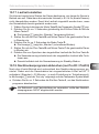
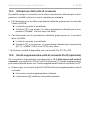
5.11. Connectingthesafetyshut-o/doorsensor 26

EN
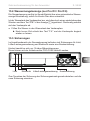
5.12. Remote start 26
5.13. Status output 26
5.14. Finishing the installation 26
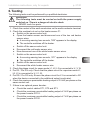
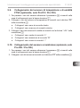
6. Testing 27
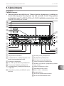
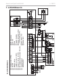
7. Connection diagram 28
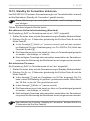
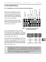
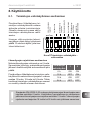
8. Commissioning 29
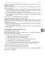
8.1. Setting the function selection switch 29
8.2. Settings in the technician menu 31
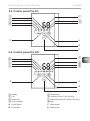
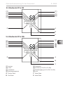
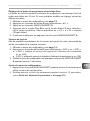
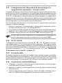
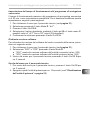
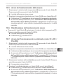
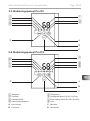
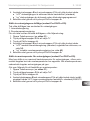
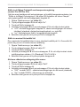
9. Controls 38
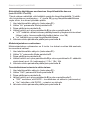
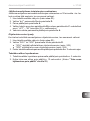
9.1. Control panel Pro D2 38
9.2. Control panel Pro D2i 38
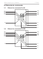
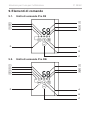
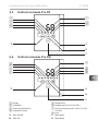
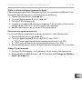
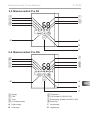
9.3. Control panel Pro D3 39
9.4. Control panel Pro D3i 39
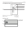
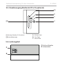
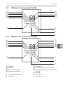
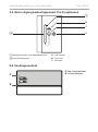
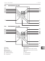
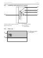
9.5. Additional output control panel Pro D (optional) 40
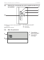
9.6. Power unit 40
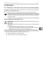
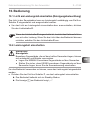
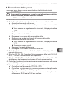
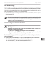
10. Operation 41
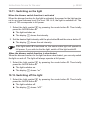
10.1. Switching on the light on the power unit (cleaning lights) 41
10.2. Switching on the power unit 41
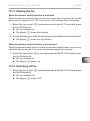
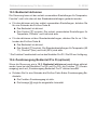
10.3. Activating the control panel 42
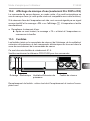
10.4. Additional output control panel Pro D (optional) 42
10.5. Starting sauna mode 43
10.6. Switchingosaunamode 43
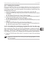
10.7. Starting combi mode (Pro D3 / Pro D3i only) 43
10.8. Switchingocombimode(ProD3/ProD3ionly) 44
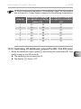
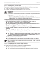
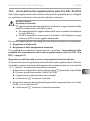
10.9. Starting additional output (Pro D2i / Pro D3i only) 45
10.10.Switchingoadditionaloutput(ProD2i/ProD3ionly) 47
10.11. Switching on the light 48
10.12.Switchingothelight 48
10.13. Starting the fan 49
10.14.Switchingofan 49

10.15. Setting the preset time 50
10.16. Cancelling the preset time feature 50
10.17. Setting the duration 51
10.18. Cancelling the post-drying program (Pro D3 / Pro D3i only) 51
10.19. Activating standby for remote operation 52
10.20.Switchingofunctions 53
10.21. Deactivating the control panel 53
10.22.Switchingothepowerunit 53
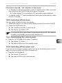
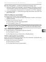
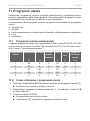
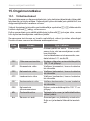
11. User programs 54
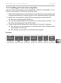
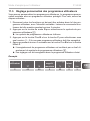
11.1. Preset user programs 54
11.2. Accessing user programs 54
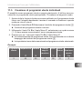
11.3. Creating your own user programs 55
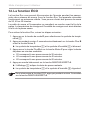
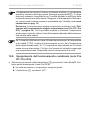
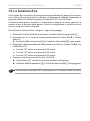
12. The Eco-function 56
13. Cleaning and maintenance 57
13.1. Cleaning 57
13.2. Maintenance 57
14. Disposal 57
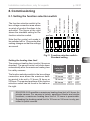
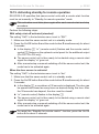
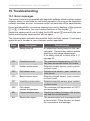
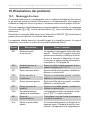
15. Troubleshooting 58
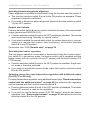
15.1. Error messages 58
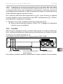
15.2. Low-water display (Pro D3 / Pro D3i only) 59
15.3. Fuses 59
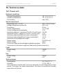
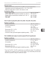
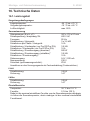
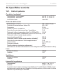
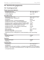
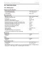
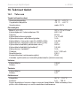
16. Technical data 60
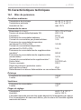
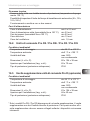
16.1. Power unit 60
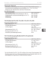
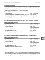
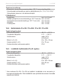
16.2. Control panel Pro D2 / Pro D2i / Pro D3 / Pro D3i 61
16.3. Additional output control panel Pro D (optional) 61

EN
Instructions for installation and use p. 5/31
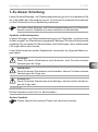
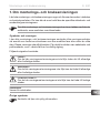
1. About this instruction manual
Read these installation and operating instructions carefully and keep them within
reach of the sauna control unit. This ensures that you can refer to information on
safety and operation at any time.
Symbols used for warning notices
In these instructions for installation and use, a warning notice located next to
an activity indicates that this activity poses a risk. Always observe the warning
notices. This prevents damage to property and injuries, which in the worst case
may be fatal.
The warning notices contain keywords, which have the following meanings:
DANGER!
Serious or fatal injury will occur if this warning notice is not observed.
WARNING!
Serious or fatal injury can occur if this warning notice is not observed.
CAUTION!
Minor injuries can occur if this warning notice is not observed.
ATTENTION!
This keyword is a warning that damage to property can occur.
Other symbols
This symbol indicates tips and useful information.
These installation and operating instructions can also be found in the
downloads section of our website: www.sentiotec.com/downloads.

Instructions for installation and use p. 6/31
2. Important information for your safety
The sauna control units of the Pro D series have been produced
in accordance with the applicable safety rules and regulations.
However, hazards may arise during use. Therefore adhere to the
followingsafetyinformationandthespecicwarningnoticesin
the individual chapters. Also observe the safety information for the
devices connected.
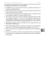
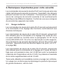
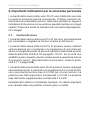
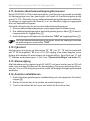
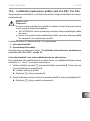
2.1. Intended use
The sauna control units of the Pro D series are used exclusively for
operating and controlling the sauna functions in accordance with
the technical data.
The sauna control units of the Pro D series may only be used for
operatingandcontrollingasaunaheaterwhichhasbeencertied
as satisfying the combustion test described in paragraph 19.101 of
EN 60335-2-53. If the heater does not meet this requirement, an
appropriate safety precaution must be taken (for example: safety
shut-o/doorsensor,see5.11onpage26).
The sauna control units of the Pro D series may only be used for
operating and controlling 3 heating circuits with a maximum heat-
ing capacity of 3.5 kW per heating circuit. The maximum vaporizer
output is 3.5 kW. The maximum additional output totals 3.5 kW.
Any use exceeding this scope is considered improper use. Improper
use can result in damage to the product, severe injuries or death.

EN
Instructions for installation and use p. 7/31
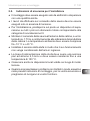
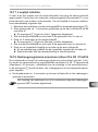
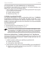
2.2. Safety information for the installer
●Installationmayonlybeperformedbyaqualiedelectricianor
similarlyqualiedperson.
●Work on the sauna control unit may only be performed when the
power has been disconnected.
●A fully disconnecting all-pole isolating device compliant with
overvoltagecategoryIIImustbettedonsite.
●The sauna control unit must be installed outside the sauna cabin
at a height of approx. 1.70 m or in accordance with the rec-
ommendation issued by the sauna manufacturer. The ambient
temperature must be within a range spanning -10 °C to +40 °C.
●The heater sensor must be installed in such a way that it is not
aectedbyinowingair.
●The heater supply cable must have a minimum cross-sectional
area of 2.5 mm2 and be temperature-resistant up to 150 °C.
●Also comply with the regulations applicable at the installation
location.
●For your own safety, consult your supplier in the event of prob-
lemsthatarenotexplainedinsucientdetailintheinstallation
instructions.

Instructions for installation and use p. 8/31
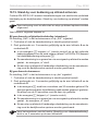
2.3. Safety information for the user
●The sauna control unit must not be used by children under 8 years
of age.
●The sauna control unit may be used by children over 8 years of
age, by persons with limited psychological, sensory or mental
capabilities or by persons with lack of experience/knowledge,
but only if:
– They are supervised.
– They have been shown how to use the device safely and
are aware of the hazards that could occur.
●Children must not play with the sauna control unit.
●Children under 14 years of age may only clean the sauna control
unit if they are supervised.
● Forhealthreasons,donotusethesaunawhenundertheinu-
ence of alcohol, medication or drugs.
● Makesurethatnoammableobjectshavebeenplacedonthe
sauna heater before the sauna control unit is switched on.
● Makesurethatnoammableobjectshavebeenplacedonthe
sauna heater before activating the preset time function or the
standby mode for remote start.
●Makesurethatnoammableobjectshavebeenplacedonor
in front of the infrared heater before the sauna control unit is
switched on.
●Makesurethatnoammableobjectshavebeenplacedonor
in front of the infrared heater before activating the preset time
function or the stand-by mode for the remote start.
●For your own safety, consult your supplier in the event of prob-
lemsthatarenotdescribedinsucientdetailintheoperating
instructions.

EN
Instructions for installation and use p. 9/31
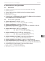
3. Product description
3.1. Scope of delivery
●Control panel (depending on version Pro D2 / D2i / D3 / D3i)
●Power unit
●Heater sensor with integrated overheat cut-out
●Sensor cables
●Installation material
●Wire jumper for bridging terminals V1 and Wm for combi heaters without
low-watershut-o
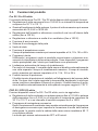
3.2. Optional accessories
●Bench sensor (1-009-231 / O-F2)
●Humidity/temperature sensor (1-010-081 / O-FTS2)
●Foil sensor (1-014-445 / P-ISX-FF)
●Power booster (1-008-779 / O-S2-18, 1-009-280 / O-S2-30)
●Safety shutdown (SFE-xxxxx)
●Home door sensor (1-052-723 / SAB00103)
●Control panel Pro D2 (1-040-159/PRO-D2-CU)
●Control panel Pro D2 white (1-040-161 / PRO-D2W-CU)
●Control panel Pro D2i (1-040-163 / PRO-D2I-CU)
●Control panel Pro D2i white (1-040-165 / PRO-D2IW-CU)
●Control panel Pro D3 (1-040-167 / PRO-D3-CU)
●Control panel Pro D3 white (1-040-169 / PRO-D3W-CU)
●Control panel Pro D3i (1-1040-173 / PRO-D3I-CU)
●Control panel Pro D3i white (1-1-040-173 /PRO-D3IW-CU)
●Additional output control panel Pro D (1-040-174 / PRO-DA-CU)
●Additional output control panel Pro D white (1-040-175 / PRO-DAW-CU)
●Pro D BUS converter RS485 (1-053-348 / BUS-CON-D)
● MySentioWi(1-053-313/S-WIFI01)
●MySentio Remote (1-053-314 / S-WIFI02)

Instructions for installation and use p. 10/31
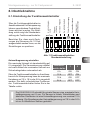
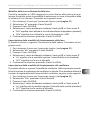
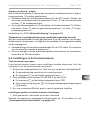
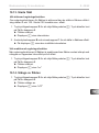
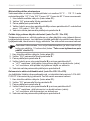
3.3. Product features
Pro D2 / Pro D2 white
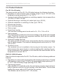
The sauna control unit Pro D2 / Pro D2 white features the following functions:
●Regulation of sauna heaters with a heating output of up to 10.5 kW in the
temperature range spanning 30 °C to 110 °C.
●A power booster allows the maximum switching capacity to be increased from
10.5 kW to 18 kW or 30 kW.
●Optional dimming or switching of a cabin light (up to 100 W)
●Optional modulation or switching of a fan (up to 100 W)
●Remote start function
●Door monitoring system
●Status output
●Preset time function
The maximum heating period can be set to 6 h, 12 h, 18 h or 24 h.
●User programs
The user programs enable favourite sauna settings to be saved and accessed
again.Thereare5presetuserprogramsavailablewhichcanbemodied
according to user requirements.
●Automatic heating time limit
The sauna control unit shuts down automatically after the maximum heating
time for safety reasons. The maximum heating period can be set to 6 h, 12 h,
18 h or 24 h.
●Overheat cut-out
The overheat cut-out is installed in the housing for the heater sensor. If a
defect causes the sauna heater to continue heating after reaching the pre-
ferredtemperature,theoverheatcut-outswitchesthesaunaheateroata
temperature of around 139 °C.
PRO D3 / PRO D3 white
Same functional scope as the Pro D2 / Pro D2 white, with the following additional
features:
●Regulation of combi-model sauna heaters with a heating output of up to 10.5 kW
and vaporizer output of up to 3.5 kW in the temperature range spanning 30 °C
to 110 °C and a humidity range spanning 0% to 100%.
●Post-drying program
After operation in combined mode, the post-drying program starts automat-
ically to prevent mould or rot from forming in the sauna cabin. This involves
heating the sauna cabin to 80°C with the fan running.
The duration can be set from OFF - 60 minutes.

EN
Instructions for installation and use p. 11/31
PRO D2i / PRO D2i white / PRO D3i / PRO D3i white
Same functional scope as the Pro D2 / Pro D2 white and the PRO D3 / PRO D3
white, with the following additional features:
●Auxiliary output
Either for dimming (up to 500 W), switching (up to 3.5 kW) or regulating the
sauna cabin temperature via the additional output.
The additional output has no overheat cut-out. For this reason, only intrinsically
safe devices should be operated using the additional output.
– If infrared heaters are connected to the additional output, they must have
an overheat cut-out. We recommend using the following infrared heaters:
●1-027-780 / DIR-350-R, 1-027-845 / WIR-350-R, 1-027-781 / DIR-500-R,
1-027-846 / WIR-500-R, 1-027-782 / DIR-750-R, 1-027-847 / WIR-750-R,
1-027-779 / DIR-1300-R
●1-027-785 / ECO-350-R, 1-027-784 / ECO-350-G, 1-027-788 / ECO-
500-R, 1-027-787 / ECO-500-G, 1-027-790 / ECO-750-R
– If one of the following infrared heating plates is connected to an additional
output, the foil sensor 1-014-445 / P-ISX-FF must be used and activated
on the technician menu (see “Activating/deactivating the foil sensor
(Pro D2i / Pro D3i only)” on page 32):
●1-028-348 / IR-WP-100, 1-028-343 / IR-WP-175, 1-028-784 / IR-WP-390,
1-028-938 / IR-WP-510
●1-028-149 / IR-WPHL-100, 1-028-941 / IR-WPHL-175, 1-028-601 / IR-
WPHL-390, 1-027-885 / IR-WPHL-510
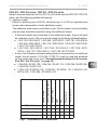
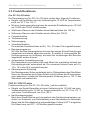
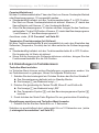
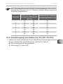
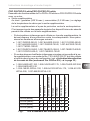
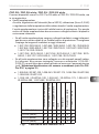
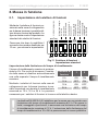
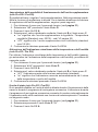
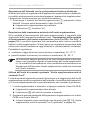
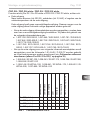
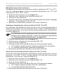
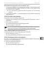
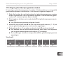
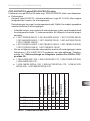
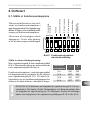
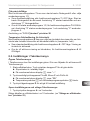
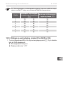
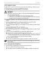
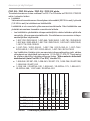
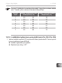
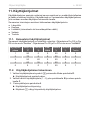
Sauna mode
Combi operating mode
Auxiliary output
Light
Fan
Preset time
User programs
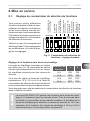
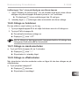
Pro D2 (white) X X X X X
Pro D2i (white) X X X X X X
Pro D3 (white) X X X X X X
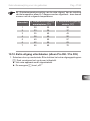
Pro D3i (white) X X X X X X X
Fig.1 Overview of Pro D functions

Instructions for installation and use p. 12/31
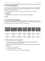
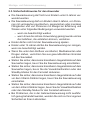
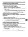
3.4. Sauna operating modes
The sauna control unit Pro D2 / Pro D2i enables sauna mode. The sauna control
unit Pro D3 / Pro D3i enables two operating modes, sauna mode and combi mode.
Sauna mode
Dry heat is provided in sauna mode. The temperature in the cabin is high (80 to
100°C). The humidity is low (no more than 10%).
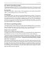
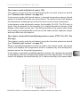
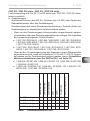
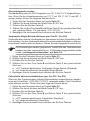
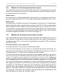
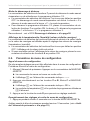
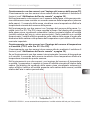
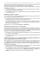
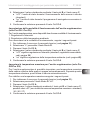
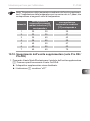
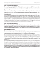
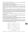
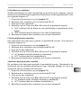
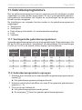
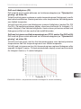
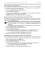
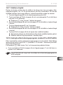
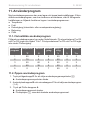
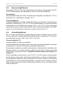
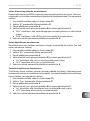
Combi mode
In combined mode, the vaporizer operates along with the heater. The temper-
ature in the sauna cabin is lower (around 40 to 65 °C) than in sauna mode, but
the relative humidity is much higher, ranging from 35% to 70%. The maximum
humidity that can be set depends on the temperature of the sauna. The higher
the sauna temperature, the lower the maximum humidity level which can be set
(see characteristic curve on page 13).
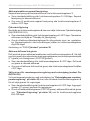
3.5. Sensor operating modes
The sauna control units of the Pro D series can be operated with one or two sen-
sors. A temperature sensor (bench sensor F2) or a humidity/temperature sensor
(FTS2, Pro D3 / Pro D3i only) can be used as the second sensor.
Single sensor mode (F1)
Single sensor mode is the factory setting.
In single-sensor mode, the sauna control unit is operated with the heater sensor
with overheat cut-out (F1) only. This is included in the scope of delivery.
The sauna control unit displays the actual temperature by default. The set tem-
perature is displayed during setting. If it is to be permanently displayed it must be
activated during commissioning (see “Temperature/humidity display (actual/
set value)” on page 31)
The maximum humidity level (only Pro D3 / Pro D3i) which can be set in sin-
gle-sensor mode is based on the temperature above the heater and the humidity
is timed. Only the setpoint for the humidity (in % relative humidity) is shown on
the display of sauna control unit. The actual humidity in the sauna cabin when
the humidity is timed depends on the size of the cabin and the vaporizer output,
andmaydierfromthesetpoint.

EN
Instructions for installation and use p. 13/31
Two-sensor mode with bench sensor (F2)
Two-sensor mode must be activated using the function selection switch
(see “Remote start release” on page 30).
In two-sensor mode with bench sensor, a second temperature sensor (bench
sensor) is installed above the rear sauna bench. The sauna control unit displays
the temperature measured by the bench sensor as the actual temperature.
In two-sensor mode with bench sensor, the humidity (Pro D3 / Pro D3i only) is
timed. Only the setpoint for the humidity (in % relative humidity) is shown on the
display of the sauna control unit. The actual humidity in the sauna cabin when
the humidity is timed depends on the size of the cabin and the vaporizer output,
andmaydierfromthesetpoint.
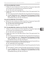
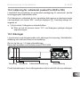
Two-sensor mode with humidity/temperature sensor (FTS2, Pro D3 / Pro
D3i only)
Two-sensor mode must be activated using the function selection switch
(see “Remote start release” on page 30).
When a humidity/temperature sensor is used in two-sensor mode, the sauna
control unit displays the temperature which is measured by the humidity/tem-
perature sensor as the actual temperature.
In two-sensor mode with humidity/temperature sensor, the vaporizer is regulated
in accordance with the humidity level measured in the sauna cabin. The sauna
control unit displays the actual humidity (in % relative humidity) in the sauna cabin.
Temperature °C
Relative humidity %
EN 60335-2-53:2011; characteristic temperature / relative humidity for proper use.

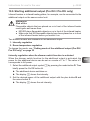
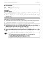
Installation instructions, only for experts p. 14/31
4. Installation
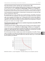
4.1. Installing the power supply unit
Observe the following points when installing the sauna control unit:
●The power unit of the sauna control unit must be installed outside the sauna
cabin or in accordance with the recommendation issued by the sauna man-
ufacturer.
●The ambient temperature must be within a range spanning -10°C to +40°C.
●The sensors may only be connected using the sensor cables supplied with
the unit, which are heat-resistant up to 150°C.
ATTENTION!
Damage to the unit
The sauna control unit is resistant to splashing water, but direct contact with
water could still damage it.
●Install the sauna control unit in a dry place at which a maximum humidity of
95% is not exceeded.
The sensor leads may be extended under the following conditions:
●A silicon cable resistant to temperatures up to 150 °C is used.
●The minimum cross-sectional of the cable is 0.5 mm2.
●The heater sensor cables may NOT be longer than 10 m.
ATTENTION!
Interference can impair signal transmission
●Route all sensor cables separately from other mains cables and control cables.
●Protect cables with only one layer of insulation by using a conduit (double
insulation).

EN
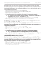
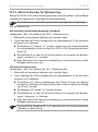
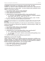
Installation instructions, only for experts p. 15/31
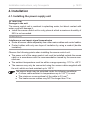
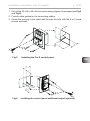
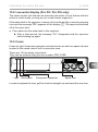
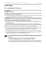
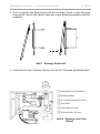
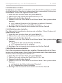
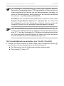
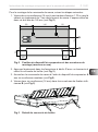
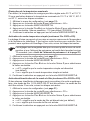
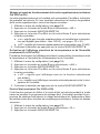
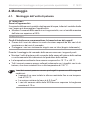
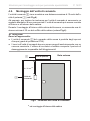
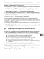
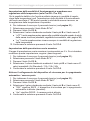
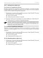
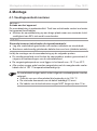
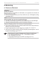
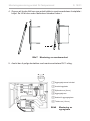
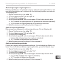
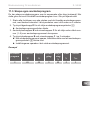
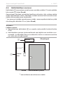
Fig.2 Position of the attachment device and the installation holes
(dimensions in mm)
C
To install the sauna control unit, perform the following steps:
1. Screw two cross-head screws (16 mm) into the wall of the sauna at a height
of approx. 1.70 m and leaving a protruding length of 7 mm. The two screws
must be placed at a distance of 145 mm from each other (see Fig.2).
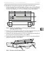
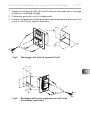
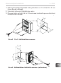
2. Press the clip locks C in lightly using a screwdriver and remove the cover
from the housing (see Fig.3).
3. Fasten the sauna control unit onto the cross-head screws using attachment
device A as an aid (see Fig.2).
4. Screw two cross-head screws (16 mm) into the lower fastening holes B
(see Fig.2).
82
80
34
175
145
34
43
40
A
B
Fig.3 Removing the cover from the housing

Installation instructions, only for experts p. 16/31
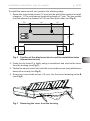
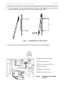
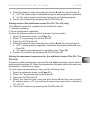
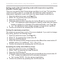
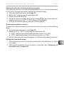
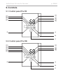
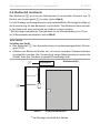
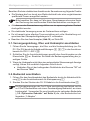
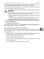
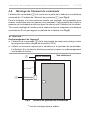
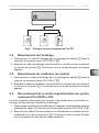
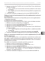
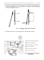
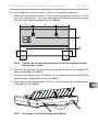
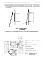
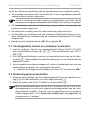
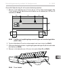
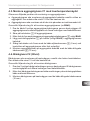
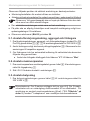
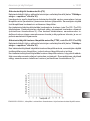
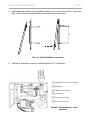
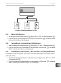
4.2. Installing the control panel
The control panel 2 is installed on the cabin wall at a maximum distance of 10
metres from the power unit 1 (see Fig.4).
For the installation, a standard jigsaw is required to cut out the recess for the
control panel. The control panel can be installed both inside and outside the cabin.
*For installation inside a sauna cabin, maintain a minimum distance of 30 cm to
the ceiling. (see Fig.4).
ATTENTION!
Damage to the unit
●The control panel 2 of the sauna control unit is splash-proof (protection
class IP IPX4).
●Work on the control panel may only be carried out using a standard screw-
driver. Using a cordless screwdriver may irreparably damage the housing.
Power unit External view
Control
panel
1
2
Fig.4 Control panel position
* when installed inside the cabin
min. 30 cm *

EN
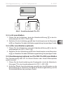
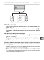
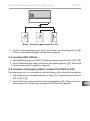
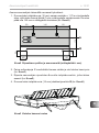
Installation instructions, only for experts p. 17/31
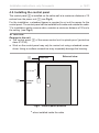
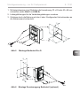
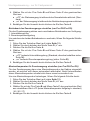
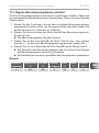
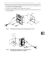
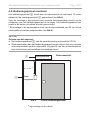
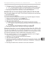
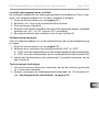
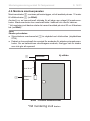
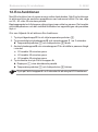
1. Cut out the 70 x 65 or 60 x 48 mm recess using a jigsaw, for example (see Fig.5
and Fig.6).
2. Provide cable guides for the connecting cables.
3. Screw the housing to the cabin wall through the hole with the 4 or 2 wood
screws enclosed.
Fig.5 Installing the Pro D control panel
65
70
20
20
5
35
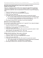
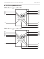
Fig.6 Installing the control panel additional output (optional)
06
48
35
20
20
3

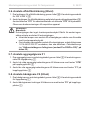
Installation instructions, only for experts p. 18/31
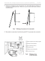
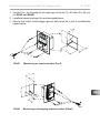
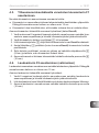
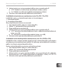
4. The front panel of the control panel is inserted with slight pressure into the
housing. Ensure that the lower catches engage noticeably.
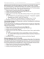
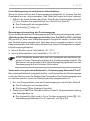
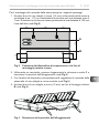
Fig.8
Installing the control panel
5. Connect the 4-pin plug to the RJ11 socket on the control panel.
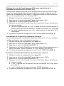
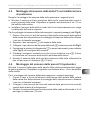
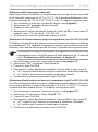
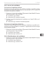
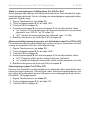
1 Heater sensor half-shells
2 Connection panel
3 Cross-head screws (9 mm)
4 Heater sensor
5 Heater sensor leads
6 Wood screws (16 mm)
Fig.7
Installing the heater
sensor
Red
White
White
Red

EN
Installation instructions, only for experts p. 19/31
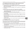
4.3. Installing the heater sensor F1 with overheat cut-out
Note the following points when installing the heater sensor:
●The heater sensor must be installed on the rear of the heater, above the
middle of the sauna heater. A distance of about 15 cm from the ceiling of the
cabin must be maintained.
●Theheatersensormustbeinstalledinsuchawaythatitisnotaectedby
inowingair.
To install the heater sensor, perform the following steps (see Fig.8):
1. Route the two 2-pole heater sensor cables in the wall of the sauna cabin
totheinstallationlocationoftheheatersensorandaxtheheatersensor
cables using cable clips.
2. Pull the two half-shells 1 of the heater sensor apart.
3. Connect the four connections for the heater sensor cable 5 in accordance
with the Fig.8.
4. Place the connection panel 2 crossways (as shown in Fig.8) in the heater
sensor half-shells.
5. Place the two half-shells together, screw them together using two cross-
head screws 3 (9 mm) and check whether the heater sensor has been
securely closed.
6. Install the heater sensor on the rear of the heater using the two wood screws
6 supplied (16 mm).
4.4. Installing the bench sensor F2 (optional)
The bench sensor must be installed on the wall of the cabin above the rear bench
seat. A distance of about 15 cm from the ceiling of the cabin must be maintained.
To install the bench sensor, carry out the following steps:
1. Route the 2-pole bench sensor lead in the wall of the sauna cabin to the
mountinglocationofthebenchsensorandaxthebenchsensorleads
using cable clips.
2. Connect the two connections for the bench sensor cable to the two middle
terminals on the connection panel.
3. Install the bench sensor on the wall of the sauna cabin using the two supplied
wood screws (16 mm).

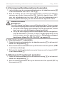
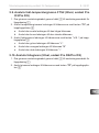
Installation instructions, only for experts p. 20/31
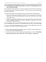
4.5. Installing humidity/temperature sensor FTS2 (optional, Pro
D3 / Pro D3i only)
The humidity/temperature sensor must be installed on the wall of the cabin above
the rear bench seat. A distance of approx. 15 cm from the ceiling of the cabin
must be maintained.
To install the humidity and temperature sensor, perform the following steps:
1. Route the 5-pole sensor cable in the wall of the sauna cabin to the mount-
ingpositionofthehumidity/temperaturesensorandaxthesensorleads
using cable clips.
2. Install the humidity/temperature sensor to the wall of the sauna cabin using
the two supplied wood screws (16 mm). Maintain a clearance of 15 cm to
the roof of the sauna cabin.
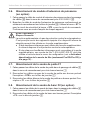
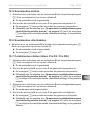
4.6. Installing foil sensor FTS2 (optional, Pro D2i / Pro D3i only)
If one or more infrared heating plates is connected to the additional output, the
foil sensor 1-014-445 / P-ISX-FF must be used:
●When installing and positioning the foil sensor, observe the operating instruc-
tions for the infrared heating plates.
●Use of a foil sensor must be activated in the technician menu (see “Activating/
deactivating the foil sensor (Pro D2i / Pro D3i only)” on page 32).
Seite wird geladen ...
Seite wird geladen ...
Seite wird geladen ...
Seite wird geladen ...
Seite wird geladen ...
Seite wird geladen ...
Seite wird geladen ...
Seite wird geladen ...
Seite wird geladen ...
Seite wird geladen ...
Seite wird geladen ...
Seite wird geladen ...
Seite wird geladen ...
Seite wird geladen ...
Seite wird geladen ...
Seite wird geladen ...
Seite wird geladen ...
Seite wird geladen ...
Seite wird geladen ...
Seite wird geladen ...
Seite wird geladen ...
Seite wird geladen ...
Seite wird geladen ...
Seite wird geladen ...
Seite wird geladen ...
Seite wird geladen ...
Seite wird geladen ...
Seite wird geladen ...
Seite wird geladen ...
Seite wird geladen ...
Seite wird geladen ...
Seite wird geladen ...
Seite wird geladen ...
Seite wird geladen ...
Seite wird geladen ...
Seite wird geladen ...
Seite wird geladen ...
Seite wird geladen ...
Seite wird geladen ...
Seite wird geladen ...
Seite wird geladen ...
Seite wird geladen ...
Seite wird geladen ...
Seite wird geladen ...
Seite wird geladen ...
Seite wird geladen ...
Seite wird geladen ...
Seite wird geladen ...
Seite wird geladen ...
Seite wird geladen ...
Seite wird geladen ...
Seite wird geladen ...
Seite wird geladen ...
Seite wird geladen ...
Seite wird geladen ...
Seite wird geladen ...
Seite wird geladen ...
Seite wird geladen ...
Seite wird geladen ...
Seite wird geladen ...
Seite wird geladen ...
Seite wird geladen ...
Seite wird geladen ...
Seite wird geladen ...
Seite wird geladen ...
Seite wird geladen ...
Seite wird geladen ...
Seite wird geladen ...
Seite wird geladen ...
Seite wird geladen ...
Seite wird geladen ...
Seite wird geladen ...
Seite wird geladen ...
Seite wird geladen ...
Seite wird geladen ...
Seite wird geladen ...
Seite wird geladen ...
Seite wird geladen ...
Seite wird geladen ...
Seite wird geladen ...
Seite wird geladen ...
Seite wird geladen ...
Seite wird geladen ...
Seite wird geladen ...
Seite wird geladen ...
Seite wird geladen ...
Seite wird geladen ...
Seite wird geladen ...
Seite wird geladen ...
Seite wird geladen ...
Seite wird geladen ...
Seite wird geladen ...
Seite wird geladen ...
Seite wird geladen ...
Seite wird geladen ...
Seite wird geladen ...
Seite wird geladen ...
Seite wird geladen ...
Seite wird geladen ...
Seite wird geladen ...
Seite wird geladen ...
Seite wird geladen ...
Seite wird geladen ...
Seite wird geladen ...
Seite wird geladen ...
Seite wird geladen ...
Seite wird geladen ...
Seite wird geladen ...
Seite wird geladen ...
Seite wird geladen ...
Seite wird geladen ...
Seite wird geladen ...
Seite wird geladen ...
Seite wird geladen ...
Seite wird geladen ...
Seite wird geladen ...
Seite wird geladen ...
Seite wird geladen ...
Seite wird geladen ...
Seite wird geladen ...
Seite wird geladen ...
Seite wird geladen ...
Seite wird geladen ...
Seite wird geladen ...
Seite wird geladen ...
Seite wird geladen ...
Seite wird geladen ...
Seite wird geladen ...
Seite wird geladen ...
Seite wird geladen ...
Seite wird geladen ...
Seite wird geladen ...
Seite wird geladen ...
Seite wird geladen ...
Seite wird geladen ...
Seite wird geladen ...
Seite wird geladen ...
Seite wird geladen ...
Seite wird geladen ...
Seite wird geladen ...
Seite wird geladen ...
Seite wird geladen ...
Seite wird geladen ...
Seite wird geladen ...
Seite wird geladen ...
Seite wird geladen ...
Seite wird geladen ...
Seite wird geladen ...
Seite wird geladen ...
Seite wird geladen ...
Seite wird geladen ...
Seite wird geladen ...
Seite wird geladen ...
Seite wird geladen ...
Seite wird geladen ...
Seite wird geladen ...
Seite wird geladen ...
Seite wird geladen ...
Seite wird geladen ...
Seite wird geladen ...
Seite wird geladen ...
Seite wird geladen ...
Seite wird geladen ...
Seite wird geladen ...
Seite wird geladen ...
Seite wird geladen ...
Seite wird geladen ...
Seite wird geladen ...
Seite wird geladen ...
Seite wird geladen ...
Seite wird geladen ...
Seite wird geladen ...
Seite wird geladen ...
Seite wird geladen ...
Seite wird geladen ...
Seite wird geladen ...
Seite wird geladen ...
Seite wird geladen ...
Seite wird geladen ...
Seite wird geladen ...
Seite wird geladen ...
Seite wird geladen ...
Seite wird geladen ...
Seite wird geladen ...
Seite wird geladen ...
Seite wird geladen ...
Seite wird geladen ...
Seite wird geladen ...
Seite wird geladen ...
Seite wird geladen ...
Seite wird geladen ...
Seite wird geladen ...
Seite wird geladen ...
Seite wird geladen ...
Seite wird geladen ...
Seite wird geladen ...
Seite wird geladen ...
Seite wird geladen ...
Seite wird geladen ...
Seite wird geladen ...
Seite wird geladen ...
Seite wird geladen ...
Seite wird geladen ...
Seite wird geladen ...
Seite wird geladen ...
Seite wird geladen ...
Seite wird geladen ...
Seite wird geladen ...
Seite wird geladen ...
Seite wird geladen ...
Seite wird geladen ...
Seite wird geladen ...
Seite wird geladen ...
Seite wird geladen ...
Seite wird geladen ...
Seite wird geladen ...
Seite wird geladen ...
Seite wird geladen ...
Seite wird geladen ...
Seite wird geladen ...
Seite wird geladen ...
Seite wird geladen ...
Seite wird geladen ...
Seite wird geladen ...
Seite wird geladen ...
Seite wird geladen ...
Seite wird geladen ...
Seite wird geladen ...
Seite wird geladen ...
Seite wird geladen ...
Seite wird geladen ...
Seite wird geladen ...
Seite wird geladen ...
Seite wird geladen ...
Seite wird geladen ...
Seite wird geladen ...
Seite wird geladen ...
Seite wird geladen ...
Seite wird geladen ...
Seite wird geladen ...
Seite wird geladen ...
Seite wird geladen ...
Seite wird geladen ...
Seite wird geladen ...
Seite wird geladen ...
Seite wird geladen ...
Seite wird geladen ...
Seite wird geladen ...
Seite wird geladen ...
Seite wird geladen ...
Seite wird geladen ...
Seite wird geladen ...
Seite wird geladen ...
Seite wird geladen ...
Seite wird geladen ...
Seite wird geladen ...
Seite wird geladen ...
Seite wird geladen ...
Seite wird geladen ...
Seite wird geladen ...
Seite wird geladen ...
Seite wird geladen ...
Seite wird geladen ...
Seite wird geladen ...
Seite wird geladen ...
Seite wird geladen ...
Seite wird geladen ...
Seite wird geladen ...
Seite wird geladen ...
Seite wird geladen ...
Seite wird geladen ...
Seite wird geladen ...
Seite wird geladen ...
Seite wird geladen ...
Seite wird geladen ...
Seite wird geladen ...
Seite wird geladen ...
Seite wird geladen ...
Seite wird geladen ...
Seite wird geladen ...
Seite wird geladen ...
Seite wird geladen ...
Seite wird geladen ...
Seite wird geladen ...
Seite wird geladen ...
Seite wird geladen ...
Seite wird geladen ...
Seite wird geladen ...
Seite wird geladen ...
Seite wird geladen ...
Seite wird geladen ...
Seite wird geladen ...
Seite wird geladen ...
Seite wird geladen ...
Seite wird geladen ...
Seite wird geladen ...
Seite wird geladen ...
Seite wird geladen ...
Seite wird geladen ...
Seite wird geladen ...
Seite wird geladen ...
Seite wird geladen ...
Seite wird geladen ...
Seite wird geladen ...
Seite wird geladen ...
Seite wird geladen ...
Seite wird geladen ...
Seite wird geladen ...
Seite wird geladen ...
Seite wird geladen ...
Seite wird geladen ...
Seite wird geladen ...
Seite wird geladen ...
Seite wird geladen ...
Seite wird geladen ...
Seite wird geladen ...
Seite wird geladen ...
Seite wird geladen ...
Seite wird geladen ...
Seite wird geladen ...
Seite wird geladen ...
Seite wird geladen ...
Seite wird geladen ...
Seite wird geladen ...
Seite wird geladen ...
Seite wird geladen ...
Seite wird geladen ...
Seite wird geladen ...
Seite wird geladen ...
Seite wird geladen ...
Seite wird geladen ...
Seite wird geladen ...
Seite wird geladen ...
Seite wird geladen ...
Seite wird geladen ...
Seite wird geladen ...
Seite wird geladen ...
Seite wird geladen ...
Seite wird geladen ...
Seite wird geladen ...
Seite wird geladen ...
Seite wird geladen ...
Seite wird geladen ...
Seite wird geladen ...
Seite wird geladen ...
Seite wird geladen ...
Seite wird geladen ...
Seite wird geladen ...
Seite wird geladen ...
Seite wird geladen ...
Seite wird geladen ...
Seite wird geladen ...
Seite wird geladen ...
Seite wird geladen ...
Seite wird geladen ...
Seite wird geladen ...
Seite wird geladen ...
Seite wird geladen ...
Seite wird geladen ...
Seite wird geladen ...
Seite wird geladen ...
Seite wird geladen ...
Seite wird geladen ...
Seite wird geladen ...
Seite wird geladen ...
Seite wird geladen ...
Seite wird geladen ...
Seite wird geladen ...
Seite wird geladen ...
Seite wird geladen ...
Seite wird geladen ...
Seite wird geladen ...
Seite wird geladen ...
Seite wird geladen ...
Seite wird geladen ...
Seite wird geladen ...
Seite wird geladen ...
Seite wird geladen ...
Seite wird geladen ...
Seite wird geladen ...
Seite wird geladen ...
Seite wird geladen ...
Seite wird geladen ...
Seite wird geladen ...
Seite wird geladen ...
Seite wird geladen ...
Seite wird geladen ...
Seite wird geladen ...
Seite wird geladen ...
Seite wird geladen ...
Seite wird geladen ...
Seite wird geladen ...
Seite wird geladen ...
Seite wird geladen ...
Seite wird geladen ...
Seite wird geladen ...
Seite wird geladen ...
Seite wird geladen ...
Seite wird geladen ...
Seite wird geladen ...
Seite wird geladen ...
Seite wird geladen ...
Seite wird geladen ...
Seite wird geladen ...
Seite wird geladen ...
Seite wird geladen ...
Seite wird geladen ...
Seite wird geladen ...
Seite wird geladen ...
Seite wird geladen ...
Seite wird geladen ...
Seite wird geladen ...
Seite wird geladen ...
Seite wird geladen ...
Seite wird geladen ...
Seite wird geladen ...
-
 1
1
-
 2
2
-
 3
3
-
 4
4
-
 5
5
-
 6
6
-
 7
7
-
 8
8
-
 9
9
-
 10
10
-
 11
11
-
 12
12
-
 13
13
-
 14
14
-
 15
15
-
 16
16
-
 17
17
-
 18
18
-
 19
19
-
 20
20
-
 21
21
-
 22
22
-
 23
23
-
 24
24
-
 25
25
-
 26
26
-
 27
27
-
 28
28
-
 29
29
-
 30
30
-
 31
31
-
 32
32
-
 33
33
-
 34
34
-
 35
35
-
 36
36
-
 37
37
-
 38
38
-
 39
39
-
 40
40
-
 41
41
-
 42
42
-
 43
43
-
 44
44
-
 45
45
-
 46
46
-
 47
47
-
 48
48
-
 49
49
-
 50
50
-
 51
51
-
 52
52
-
 53
53
-
 54
54
-
 55
55
-
 56
56
-
 57
57
-
 58
58
-
 59
59
-
 60
60
-
 61
61
-
 62
62
-
 63
63
-
 64
64
-
 65
65
-
 66
66
-
 67
67
-
 68
68
-
 69
69
-
 70
70
-
 71
71
-
 72
72
-
 73
73
-
 74
74
-
 75
75
-
 76
76
-
 77
77
-
 78
78
-
 79
79
-
 80
80
-
 81
81
-
 82
82
-
 83
83
-
 84
84
-
 85
85
-
 86
86
-
 87
87
-
 88
88
-
 89
89
-
 90
90
-
 91
91
-
 92
92
-
 93
93
-
 94
94
-
 95
95
-
 96
96
-
 97
97
-
 98
98
-
 99
99
-
 100
100
-
 101
101
-
 102
102
-
 103
103
-
 104
104
-
 105
105
-
 106
106
-
 107
107
-
 108
108
-
 109
109
-
 110
110
-
 111
111
-
 112
112
-
 113
113
-
 114
114
-
 115
115
-
 116
116
-
 117
117
-
 118
118
-
 119
119
-
 120
120
-
 121
121
-
 122
122
-
 123
123
-
 124
124
-
 125
125
-
 126
126
-
 127
127
-
 128
128
-
 129
129
-
 130
130
-
 131
131
-
 132
132
-
 133
133
-
 134
134
-
 135
135
-
 136
136
-
 137
137
-
 138
138
-
 139
139
-
 140
140
-
 141
141
-
 142
142
-
 143
143
-
 144
144
-
 145
145
-
 146
146
-
 147
147
-
 148
148
-
 149
149
-
 150
150
-
 151
151
-
 152
152
-
 153
153
-
 154
154
-
 155
155
-
 156
156
-
 157
157
-
 158
158
-
 159
159
-
 160
160
-
 161
161
-
 162
162
-
 163
163
-
 164
164
-
 165
165
-
 166
166
-
 167
167
-
 168
168
-
 169
169
-
 170
170
-
 171
171
-
 172
172
-
 173
173
-
 174
174
-
 175
175
-
 176
176
-
 177
177
-
 178
178
-
 179
179
-
 180
180
-
 181
181
-
 182
182
-
 183
183
-
 184
184
-
 185
185
-
 186
186
-
 187
187
-
 188
188
-
 189
189
-
 190
190
-
 191
191
-
 192
192
-
 193
193
-
 194
194
-
 195
195
-
 196
196
-
 197
197
-
 198
198
-
 199
199
-
 200
200
-
 201
201
-
 202
202
-
 203
203
-
 204
204
-
 205
205
-
 206
206
-
 207
207
-
 208
208
-
 209
209
-
 210
210
-
 211
211
-
 212
212
-
 213
213
-
 214
214
-
 215
215
-
 216
216
-
 217
217
-
 218
218
-
 219
219
-
 220
220
-
 221
221
-
 222
222
-
 223
223
-
 224
224
-
 225
225
-
 226
226
-
 227
227
-
 228
228
-
 229
229
-
 230
230
-
 231
231
-
 232
232
-
 233
233
-
 234
234
-
 235
235
-
 236
236
-
 237
237
-
 238
238
-
 239
239
-
 240
240
-
 241
241
-
 242
242
-
 243
243
-
 244
244
-
 245
245
-
 246
246
-
 247
247
-
 248
248
-
 249
249
-
 250
250
-
 251
251
-
 252
252
-
 253
253
-
 254
254
-
 255
255
-
 256
256
-
 257
257
-
 258
258
-
 259
259
-
 260
260
-
 261
261
-
 262
262
-
 263
263
-
 264
264
-
 265
265
-
 266
266
-
 267
267
-
 268
268
-
 269
269
-
 270
270
-
 271
271
-
 272
272
-
 273
273
-
 274
274
-
 275
275
-
 276
276
-
 277
277
-
 278
278
-
 279
279
-
 280
280
-
 281
281
-
 282
282
-
 283
283
-
 284
284
-
 285
285
-
 286
286
-
 287
287
-
 288
288
-
 289
289
-
 290
290
-
 291
291
-
 292
292
-
 293
293
-
 294
294
-
 295
295
-
 296
296
-
 297
297
-
 298
298
-
 299
299
-
 300
300
-
 301
301
-
 302
302
-
 303
303
-
 304
304
-
 305
305
-
 306
306
-
 307
307
-
 308
308
-
 309
309
-
 310
310
-
 311
311
-
 312
312
-
 313
313
-
 314
314
-
 315
315
-
 316
316
-
 317
317
-
 318
318
-
 319
319
-
 320
320
-
 321
321
-
 322
322
-
 323
323
-
 324
324
-
 325
325
-
 326
326
-
 327
327
-
 328
328
-
 329
329
-
 330
330
-
 331
331
-
 332
332
-
 333
333
-
 334
334
-
 335
335
-
 336
336
-
 337
337
-
 338
338
-
 339
339
-
 340
340
-
 341
341
-
 342
342
-
 343
343
-
 344
344
-
 345
345
-
 346
346
-
 347
347
-
 348
348
-
 349
349
-
 350
350
-
 351
351
-
 352
352
-
 353
353
-
 354
354
-
 355
355
-
 356
356
-
 357
357
-
 358
358
-
 359
359
-
 360
360
-
 361
361
-
 362
362
-
 363
363
-
 364
364
-
 365
365
-
 366
366
-
 367
367
-
 368
368
-
 369
369
-
 370
370
-
 371
371
-
 372
372
-
 373
373
-
 374
374
-
 375
375
-
 376
376
-
 377
377
-
 378
378
-
 379
379
-
 380
380
-
 381
381
-
 382
382
-
 383
383
-
 384
384
-
 385
385
-
 386
386
-
 387
387
-
 388
388
-
 389
389
-
 390
390
-
 391
391
-
 392
392
-
 393
393
-
 394
394
-
 395
395
-
 396
396
-
 397
397
-
 398
398
-
 399
399
-
 400
400
-
 401
401
-
 402
402
-
 403
403
-
 404
404
-
 405
405
-
 406
406
-
 407
407
-
 408
408
-
 409
409
-
 410
410
-
 411
411
-
 412
412
-
 413
413
-
 414
414
-
 415
415
-
 416
416
-
 417
417
-
 418
418
-
 419
419
-
 420
420
-
 421
421
-
 422
422
-
 423
423
-
 424
424
-
 425
425
-
 426
426
-
 427
427
-
 428
428
-
 429
429
-
 430
430
-
 431
431
-
 432
432
-
 433
433
-
 434
434
-
 435
435
-
 436
436


in anderen Sprachen
- English: Sentiotec Pro D User manual
- français: Sentiotec Pro D Manuel utilisateur
- italiano: Sentiotec Pro D Manuale utente
- Nederlands: Sentiotec Pro D Handleiding
- svenska: Sentiotec Pro D Användarmanual
Verwandte Artikel
-
Sentiotec Pro C2 Benutzerhandbuch
-
-
-
-
-
-
-
-
-
Andere Dokumente
-
EOS Bi-O Mat U Assembly And Operating Instruction
-
Karibu 87147 Building Instructions
-
HARVIA CP-RMC-75 Instructions For Installation And Use Manual
-
-
 Sawotec Nordex NEXT NR-90NB Benutzerhandbuch
-
 Sanotechnik D50520 Mounting And Using Instructions
-
 Infraworld TrioSol Unica 3 Benutzerhandbuch
-
Interline 42250001 Benutzerhandbuch


