TE Connectivity 2120892-1 Bedienungsanleitung
- Typ
- Bedienungsanleitung

Instruction sheets / Installationsanleitung
411-18570
9-NOV-2015 Rev. B
Instruction sheets / Installationsanleitung
411-18570
9-NOV-2015 Rev. B
RJ45 CAT 6A PLUG, IP20 INDUSTRIAL ETHERNET RJ45 CAT 6A PLUG, IP20 INDUSTRIAL ETHERNET
All specifications subject to change. Consult TE Connectivity for latest specifications. te.com.
Für technische Daten sind ausschließlich die neuesten TE Connectivity Kundenzeichnungen bzw. Produktspezifikationen
verbindlich. Weitere Informationen unter te.com
1. Note / Hinweis
This manual describes the assembly of CAT 6A PLUG, IP20 (PN 2120892-1)
Read installation instructions carefully before connecting.
Diese Anleitung beschreibt die Montage des RJ45 Steckverbinder CAT 6A, IP20
(PN 2120892-1)
Vor dem Anschluss Montageanleitung sorgfältig lesen.
2. Technical Data / Technische Daten
Operating temperature/Betriebstemperatur: -40°C … +85°C
Wire cross-section/Drahtquerschnitt: AWG 26/1 – AWG 22/1,
AWG 26/7 – AWG 22/7
Insulation Diameter/Isolationsdurchmesser: Ø 0.88 mm – 1.5 mm
Cable outer diameter/Kabelaußendurchmesser: Ø 5.8 mm – 8.2 mm
3. Content of Packaging / Inhalt der Verpackung
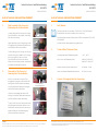
5.
Final Assembly of the Connector /
Endmontage des Steckverbinders
Continue sliding the IP20 housing onto the plug.
Das IP20 Gehäuse in der richtigen Orientierung
über den Stecker führen.
Slightly push down on the locking spring in order
to engage the plug. Rastfeder niederhalten und
in die Rastlasche am Stecker einführen.
Continue sliding the IP20 housing onto the plug
until the locking lances audible click. Following
this action, tighten the cable screw joint.
Das IP20 Gehäuse weiter über den Stecker
führen, bis dieser hörbar verrastet. Anschließend
die Kabelverschraubung fest anziehen.
Push down
KLICK
6. Disassembly of the Connector /
Demontage des Steckverbinders
At first, loosen the cable screw joint. Then,
disengage the locking lances and slide the IP20
housing back. Zuerst die Kabelverschraubung
lösen. Anschließend die Rastlaschen entriegeln
und das IP20 Gehäuse zurückführen.
Lift up the locking spring and slide the IP20
housing out completely. Rastfeder anheben und
das IP20 Gehäuse komplett zurückführen.
To get the cables free, open the upper and lower
part of plug parallel, and then rotate the covers.
Gehäuseober- und Unterteil des Steckers zuerst
parallel und dann mit einer Drehbewegung
öffnen um das Kabel zu entnehmen.
Locking latches/
Verriegelungsfeder
te.com
2120897-1 IND WR 09/2015. © 2015 TE Connectivity. All Rights Reserved. TE Connectivity and TE connectivity (logo) are trademarks.
Other logos, products and/or company names mentioned herein may be trademarkes of their respective owners.

Instruction sheets / Installationsanleitung
411-18570
9-NOV-2015 Rev. B
Instruction sheets / Installationsanleitung
411-18570
9-NOV-2015 Rev. B
RJ45 CAT 6A PLUG, IP20 INDUSTRIAL ETHERNET RJ45 CAT 6A PLUG, IP20 INDUSTRIAL ETHERNET
All specifi cations subject to change. Consult TE Connectivity for latest specifi cations. te.com.
Für technische Daten sind ausschließlich die neuesten TE Connectivity Kundenzeichnungen bzw. Produktspezifi kationen
verbindlich. Weitere Informationen unter te.com
All specifi cations subject to change. Consult TE Connectivity for latest specifi cations. te.com.
Für technische Daten sind ausschließlich die neuesten TE Connectivity Kundenzeichnungen bzw. Produktspezifi kationen
verbindlich. Weitere Informationen unter te.com
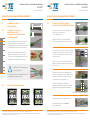
4. Assembly Procedure /
Montageschritte
4.1 Preparation of connector
and Ethernet cable /
Vorbereiten von Steckverbinder
und Ethernetkabel
• Insert the cable into the IP 20 housing and
strip the cable acc. to the fi gure below.
• Straighten the wires by hand and cut them at
a slight angle to make the assembly easier.
• Kabel in das IP20 Gehäuse einführen und
Kabel nach Abbildung rechts abisolieren.
• Die Adern von Hand begradigen und schräg
ablängen, um die Montage zu erleichtern.
!
min. 60 mm
4.5 - 5.5 mm
cut
4.2 Colorcoding / Farbzuordnung
Typ: 568 A Typ: 568 B Industrial (Profi net)
• Shielding or foils should be intact
as long as possible.
• Schirmgefl echt bzw. Folien möglichst weit mit
den gepaarten Leitungen führen.
4.3 Connection of Ethernet Cable /
Anschließen der Industrial Ethernetkabel
The exposed wires can be pulled off easily.
Überstehende Adern können einfach
abgezogen werden.
Terminate the wires by pressing upper and
lower cover together as shown in fi gure below.
Termination may be done using your fi ngers
or with a parallel closing hand tool.
Drücken Sie das Gehäuseoberteil und
Gehäuseunterteil mit den Fingern oder einem
parallel schließenden Werkzeug zusammen.
Pull on the wires to correctly position the cable
shielding. It must be adjacent to the connector
in order to create a proper connection with the
connector shield.
Ziehen Sie die Adern so weit heraus, dass der
Kabelschirm in der Schirmkontaktierung korrekt
positioniert ist.
Insert the wires into the cable manager, pay
attention to the wire position
(Colorcoding from 4.2).
Einführen der Adern in die Kabelführung,
auf richtige Farbzuordung achten (siehe 4.2).
Position for tool/Werkzeugposition
60 mm
55 0
5
-
 1
1
-
 2
2


TE Connectivity 2120892-1 Bedienungsanleitung
- Typ
- Bedienungsanleitung
in anderen Sprachen
Andere Dokumente
-
Hager WDI10 series Benutzerhandbuch
-
Hirschmann RSPM2022 Benutzerhandbuch
-
MADRIX LUNA 8 Quick Start Manual & Technical Manual
-
Rutenbeck 13900308 - UM-Cat.8.1/Class I Benutzerhandbuch
-
-
Telegaertner 100023197 Assembly Instruction
-
-
 Rockford Fosgate Punch FRC1205 Bedienungsanleitung
