Rutenbeck 13900308 - UM-Cat.8.1/Class I Benutzerhandbuch
- Typ
- Benutzerhandbuch

Cat.8.1/Class I Universalmodul
Cat.8.1/Class I Universal Module
Montageanleitung | Installation instructions
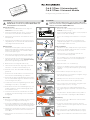
Installation
In order to prevent malfunctioning, only use patch cables that
have been tested according to ISO/IEC 61935-2 with connectors
that are conform with ISO/IEC 60603-7-81.
Preparing the cable
1 Remove the cable sheathing along a total length of
minimum 40 mm (see Fig. 1).
2 Shorten the braided shield to approx. 10 mm (A) and pull
it back over the cable sheathing.
3 Remove the shielding foil and untwist the four wire pairs
(B).
4 Shorten the two wire pairs at a connecting end (e. g.
orange/brown) by approx. 10 mm longer than the other
two and slightly chamfer the ends.
Cable installation
5 Untwist the wire pairs. Initially insert the longer wire pairs
(C) in the wire distributor that has the same colour and
follow with the shorter wire pairs.
6 Firmly insert the corresponding wire pairs into the
coloured wire fixations (E) by hand.
7 Use a cutting tool (F) to shorten the protruding ends of
the wires so that all of the wires are flush (G) with the
tension relief part.
8 Open the module cover on the back (H).
9 Insert the wire distributor into the module head (I) ensur-
ing that it is correctly positioned (with the groove facing
upwards).
10 Ensure that the dust protection cap (K) is open.
11 Swivel the module cover in and press it together using a
pair of parallel action pliers (L).
12 Manually remove the other tension relief (J) from the
plastic holder and insert it into the guide rail (M).
13 Also lock this tension relief into place using a pair of par-
allel action pliers (2x click) – see Fig. 6.
14 If necessary, place the equipotential bonding (N) onto
the contact tongue (O, 2.8 mm flat connector) as shown
in Fig. 7.
15 Should it interfere, break the plastic holder (P) that is no
longer required after completing the cable installation.
Dismantling
16 In order to remove the cable from the universal module,
work in reverse order.
17 To open the universal module, press the unlocking
springs on the tension relief together and pull it out of the
guide from above.
18 Unlock the module cover by applying pressure using a
pair of parallel action pliers and swivel it back (see Fig. 8).
19 Remove the wire distributor from the back of the module
head.
Installation
Verwenden Sie ausschließlich geprüfte Patchkabel gemäß
ISO/IEC 61935-2 mit Steckern gemäß ISO/IEC 60603-7-81
um Fehlfunktionen zu vermeiden!
Kabelvorbereitung
1 Entfernen Sie den Kabelmantel auf einer Länge von
mindestens 40 mm (siehe Abb. 1).
2 Kürzen Sie den Geflechtschirm auf ca. 10 mm (A) und
ziehen diesen nach hinten über den Kabelmantel.
3 Entfernen Sie die Schirmfolie und entdrillen Sie die vier
Adernpaare (B).
4 Kürzen Sie zwei Adernpaare einer Anschlussseite (z. B.
orange/braun) um ca. 10 mm mehr als die beiden anderen
und schrägen Sie alle Enden leicht ab.
Kabelmontage
5 Entdrillen Sie die Adernpaare. Führen Sie zuerst die
längeren Adernpaare (C) in die farblich zugehörigen
Kammern des Adernverteilers ein und lassen dann die
kürzeren Adernpaare folgen.
6 Ziehen Sie die jeweiligen Adernpaare in die farbig mar-
kierten Adernfixierungen (E) mit der Hand fest hinein.
7 Kürzen Sie jetzt mit einem Schneidewerkzeug (F) die
überstehenden Aderenden, sodass alle Adern bündig
(G) mit dem Zugentlastungsteil abschließen.
8 Öffnen Sie den rückseitigen Moduldeckel (H).
9 Führen Sie den Adernverteiler lagerichtig – mit der Nut
nach oben – von hinten in den Modulkopf (I) ein.
10 Stellen Sie sicher, dass die Staubschutzkappe (K)
geöffnet ist.
11 Schwenken Sie den Moduldeckel ein und drücken Sie
diesen mit einer Parallelhubzange (L) zusammen.
12 Nehmen Sie die andere Zugenlastung (J) mit der Hand
aus der Kunststoffhalterung heraus und führen Sie diese
in die Führungsschiene (M) ein.
13 Verrasten Sie auch diese Zugentlastung mit einer Paral-
lelhubzange fest (2x Klick) – siehe Abb. 6.
14 Bei Bedarf stecken Sie den Potentialausgleich (N) – wie
in Abb. 7 dargestellt – auf die Kontaktzunge (O, Flach-
steckverbinder 2,8 mm).
15 Wenn störend, brechen Sie zum Abschluss der Kabel-
montage die nicht mehr benötigte, weiße Kunststoffhal-
terung (P) ab.
Demontage
16 Gehen Sie zur Entnahme des Kabels aus dem Universal-
modul generell in umgekehrter Reihenfolge vor.
17 Drücken Sie zum Öffnen des Universalmoduls die seit -
lichen Entriegelungsfedern der Zugentlastung zusammen
und nehmen diese nach oben aus der Führung heraus.
18 Entrasten Sie den Moduldeckel mittels Druck einer Paral-
lelhubzange und schwenken diesen nach hinten auf –
siehe Abb. 8.
19 Entnehmen Sie den Adernverteiler von hinten aus dem
Modulkopf.
Technical Support
+ 4 9 2 3 5 5 82-111
Commercial Support
+49 2355 82-137
4J
H
I
5
L K
6
7
8
N O
P
1A B
10 6min. 40 mm
3FG
2
D
C
E
M

© Wilhelm Rutenbeck GmbH & Co. KG · 293 810 · 139 003 08 · Rut053 · Stand/Status 06.18 · Technische Änderungen vorbehalten/Subjected to technical changes
Klagebach 33
58579 Schalksmühle
Telefon +49-(0) 23 55-82-0
Telefax +49-(0) 23 55-82-105
www.rutenbeck.de
Cat.8.1 Universalmodul
Schutzart IP20 gemäß DIN EN 60529 | IP20 as defined in DIN EN 60529 Protection Class
Umgebungstemperatur -40 bis | to +85 °C Ambient temperature
Massive Leiter Ein Leiter 0,57–0,64 mm Ø, AWG 22/1-23/1 | One conductor 0.57-0.64 mm ø, AWG 22/1-23/1
Ø außen: 0,7–1,6 mm, PE, eine Ader je Kontakt | outer Ø 0.7-1.6 mm, PE, one wire per contact Solid conductor
Lebensdauer ≥ 750 Steckzyklen | mating cycles Service life
Nennspannung 72 V DC, geeignet für TNV-Stromkreise gemäß EN 62368-1
72 V DC, suitable for electric TNV circuits in accordance with EN 62368-1 Rated voltage
Betriebsstrom 500 mA bei 50 °C Umgebungstemperatur | 500 mA at an ambient temperature of 50 °C Operating current
PoE+ Tauglichkeit gemäß IEEE 802.2at | in accordance with IEEE 802.2at PoE+ suitability
Spannungsfestigkeit 1.000 V (Kontakt-Kontakt) | 1.000 V (contact-contact)
1.500 V (Kontakt-Gehäuse) | 1.500 V (contact-housing) Dielectric strength
Isolationswiderstand ≥ 500 MΩ Insulation resistance
Kontaktwiderstand Signalkontakt | Signal contact: 20 mΩ
Schirmkontakt | Shield contact: 100 mΩ Contact resistance
Übertragungs-
technische
Eigenschaften
ISO/IEC TR 11801-9901:2014-10, Class I
ISO/IEC 11801-1:2017-11, Cat.8.1/Class I, geschirmt | shielded
TIA-568-C.2-1:2016-07, Cat.8 geschirmt | shielded
Transmission
characteristics
Sonstiges halogenfrei | halogen-free Miscellaneous
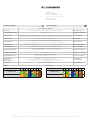
Technische Daten Technical Data
Farbcode Colour code
Anschlussklemme
TIA/EIA-568-A
TIA/EIA-568-B
1 2 3 4 5 6 7 8 Connecting terminal
TIA/EIA-568-A
TIA/EIA-568-B
1 2 3 4 5 6 7 8
-
 1
1
-
 2
2


Rutenbeck 13900308 - UM-Cat.8.1/Class I Benutzerhandbuch
- Typ
- Benutzerhandbuch
in anderen Sprachen
Verwandte Artikel
Andere Dokumente
-
Lindy 20703 Benutzerhandbuch
-
Renkforce 24 ports Network patch panel CAT 6 1 U Bedienungsanleitung
-
-
-
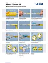 Leoni MegaLine Connect45 Installationsanleitung
-
Triotronik PKW-TOUGH-K6 20.0 GE Datenblatt
-
-
-
Telegaertner 100023197 Assembly Instruction
-
 TE Connectivity 2120892-1 Bedienungsanleitung

