Thermaltake Level 10 GT Battle Edition Benutzerhandbuch
- Kategorie
- Computergehäuse
- Typ
- Benutzerhandbuch
Seite wird geladen ...
Seite wird geladen ...

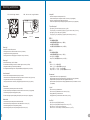
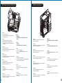
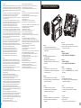
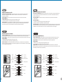
<190 mm
<360 mm
CPU Cooler Height Limitation VGA (Add- on card) Length Limitation
3 4
Warning and Notice
Warning!!
- Height limit for the CPU heatsink:
The height limit for the CPU heatsink is 190 mm (7.5 inches).
- Length limit for the VGA (graphics card):
The length limit for the VGA (graphics card) is 360 mm (14.2 inches).
Warnung!!
- Höhenbeschränkung für CPU-Kühler:
Die Höhenbeschränkung für den CPU-Kühler liegt bei 190 mm (7,5 Zoll).
- Längenbeschränkung für die VGA (Grafikkarte):
Die Längenbeschränkung für die VGA (Grafikkarte) beträgt 360 mm (14,2 Zoll).
Avertissement !
- Hauteur limite du dissipateur thermique du processeur :
La hauteur limite du dissipateur thermique du processeur est de 190 mm (7,5 pouces).
- Longueur limite de la carte VGA (carte graphique) :
La longueur limite de la carte VGA (carte graphique) est de 360 mm (14,2 pouces).
Precaución
- Límite de altura para el disipador de calor de la CPU:
El límite de altura para el disipador de calor de la CPU es de 190 mm (7,5 pulgadas).
- Límite de longitud para la tarjeta gráfica (VGA):
El límite de longitud para la tarjeta gráfica (VGA) en de 360 mm (14,2 pulgadas).
Attenzione!
- Limite di altezza per il dissipatore di calore della CPU:
Il limite di altezza per il dissipatore di calore della CPU è 190 mm (7,5").
- Limite di lunghezza per la VGA (schede grafiche):
Il limite di lunghezza per la VGA (scheda grafica) è 360 mm (14,2").
Atenção!!
- Limite de altura para o dissipador do CPU:
O limite de altura para o dissipador do CPU é 190 mm (7,5 polegadas).
- Limite de comprimento para VGA (placa gráfica):
O limite de comprimento para VGA (placa gráfica) é 360 mm (14,2 polegadas).
Προειδοποίηση!!
- Όριο ύψους για τον αποδέκτη θερμότητας της CPU:
Το όριο ύψους για τον αποδέκτη θερμότητας της CPU είναι 190 mm (7,5 ίντσες).
- Όριο μήκους για την VGA (κάρτα γραφικών):
Το όριο μήκους για τη VGA (κάρτα γραφικών) είναι 360 mm (14,2 ίντσες).
警告!!
- CPU散熱器的高度限制:
CPU散熱器的高度限制為190mm ( 7.5英吋 )。
- VGA(顯示卡)的長度限制:
VGA(顯示卡)的長度限制為360mm (14.2英吋 )。
警告!!
- CPU散热器的高度限制:
CPU散热器的高度限制为190mm(7.5英寸)。
- VGA(显卡)的长度限制:
VGA(显卡)的长度限制为360mm(14.2英寸)。
警告
- CPUヒートシンクの高さ制限:
CPUヒートシンクの高さ制限は190 mmです。
- VGA(グラフィックスカード)の長さ制限:
VGA(グラフィックスカード)の長さ制限は360 mmです。
Внимание!
- Ограничение по высоте для радиатора ЦП.
Ограничение по высоте для радиатора ЦП составляет 190 мм (7,5 дюйма).
- Ограничение по длине для платы VGA (графическая плата).
Ограничение по длине для платы VGA (графическая плата) составляет 14.2 мм
(14,2 дюйма).
Uyarı!!
- CPU ısı alıcısı için yükseklik sınırı:
CPU ısı alıcısı için yükseklik sınırı 190 mm’dir (7,5 inç).
- VGA (grafik kartı) için uzunluk sınırı:
VGA (grafik kartı) için uzunluk sınırı 360 mm’dir (14,2 inç).
คำเตือน!!
- ขีดจำกัดความสูงสำหรับฮีตซิงก์ของ CPU:
ขีดจำกัดความสูงสำหรับฮีตซิงก์ของ CPU คือ 190 มม. (7.5 นิ้ว)
- ขีดจำกัดความยาวสำหรับ VGA (การ์ดแสดงผล):
ขีดจำกัดความยาวสำหรับ VGA (การ์ดแสดงผล) คือ 360 มม. (14.2 นิ้ว)
藍色線條為尺寸標示,請勿印刷上去!
產品料號
VN10008W2N
L e v e l 1 0 G T B A T T L E
說明書 12/03/02 A
產品名稱
印刷項目
子件料號
發稿日期
版本
騎馬釘32 8 0 4
雙銅
157G
P X
書寫紙
單色 無無
其他特殊處理效果表面處理
2
厚度(g/m )
裝訂方式 材質頁數 印刷色彩
規格樣式
整本
MARKETING CHECK DESIGN
PRODUCT GM
其他特殊處理效果表面處理
2
厚度(g/m )
材質印刷色彩
封面樣式(當封面與內頁 樣式不 同時尚 須填寫)
Pei
刀模線
125 mm
176 mm
色
亮

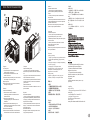
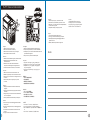
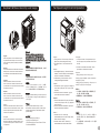
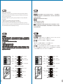
Side Panel Disassembly
English /
Left side panel
1. Turn the keyhole of the side panel into the
OPEN position using the key.
2. Push and hold the release button on the
bottom of the case.
3.Rotate the side panel away from case and then
lift vertically to remove the panel.
Right side panel
Remove the screws on the back of the chassis,
and open the side panel.
Deutsch /
Linke Seitenverkleidung
1. Drehen Sie das Schloss der linken
Verkleidung mithilfe des Schlüssels in die
Position OFFEN
2. Drücken und halten Sie den
Verriegelungsknopf am unteren Rand des
Gehäuses.
3. Drehen Sie die Seitenverkleidung vom
Gehäuse weg und heben Sie sie dann vertikal
an, um sie zu entfernen.
Rechte Seitenverkleidung
Entfernen Sie die Schrauben auf der Rückseite
des Gehäuses und öffnen Sie das Seitenteil.
Français /
Panneau latéral gauche
1. Tournez le trou de la serrure du panneau
latéral dans la position OUVERTE en utilisant la
clé.
2. Appuyez sur le bouton de libération au bas du
boîtier et maintenez-le enfoncé.
3. Faites tourner le panneau latéral en l’écartant
du boîtier et ensuite, soulevez-le verticalement
pour l’enlever.
Panneau latéral droit
Enlevez les vis à l’arrière du châssis et ouvrez le
panneau latéral.
Español /
Panel lateral izquierdo
1. Gire el ojo de la cerradura del panel lateral a
la posición OPEN (ABIERTO) utilizando la llave.
2. Empuje y sostenga el botón de liberación de
la parte inferior de la tapa.
3. Gire el panel lateral hacia el lado opuesto de
la tapa y, a continuación, levante verticalmente
para quitar el panel.
Panel lateral derecho
Extraiga los tornillos de la parte posterior de la
caja y abra el panel lateral.
Italiano /
Pannello laterale sinistro
1. Ruotare il foro del pannello laterale in
posizione OPEN (APERTO) utilizzando la
chiave.
2. Tenere premuto il pulsante di rilascio alla
base del case.
3. Ruotare il pannello laterale lontano dal case e
sollevare lateralmente per rimuovere il pannello.
Pannello laterale destro
Rimuovere le viti sulla parte posteriore dello
chassis e aprire il pannello laterale.
Português/
Painel lado esquerdo
1. Rode o orifício do painel lateral para a
posição OPEN (aberto), com a chave.
2. Mantenha premido o botão para abrir na parte
inferior da caixa.
3. Rode o painel lateral, afastando da caixa e
levante para remover o painel.
Painel lado direito
Remova os parafusos na parte de trás da caixa e
abra o painel lateral.
Ελληνικά/
Αριστερός πίνακας
1. Στρέψτε την κλειδαριά του εμπρόσθιου πίνακα
στη θέση OPEN (ΑΝΟΙΧΤΟ) χρησιμοποιώντας
το κλειδί.
2. Σπρώξτε και κρατήστε το κουμπί απασφάλισης
στον πάτο της θήκης.
3. Περιστρέψτε τον πλευρικό πίνακα
απομακρύνοντάς τον από τη θήκη και μετά
ανασηκώστε τον κατακόρυφα για να τον
αφαιρέσετε από τον πίνακα.
Δεξιός πίνακας
Αφαιρέστε τις βίδες από το πίσω μέρος του
πλαισίου, και ανοίξτε τον πλευρικό πίνακα.
繁體中文 /
左側板
1. 用鑰匙將側板鎖孔轉至OPEN位置。
2. 按壓機殼底部側板釋放鈕。
3. 轉動並向上抬升至移除左側板。
右側板
移除機殼後方螺絲,將側板打開。
日本語 /
左側のパネル
1. かぎを使用し、側面パネルのかぎ穴を回し
てOPEN(開く)位置にします。
2. ケース下部の解除ボタンを押したままにし
ます。
3. 側面パネルをケースから遠ざけるように回
転し、垂直に持ち上げてパネルを取り外しま
す。
右側のパネル
シャーシ背面のねじを取り外し、サイドパネ
ルを開きます。
Русский /
1. С помощью ключа поверните отверстие
под ключ на боковой панели в положение
OPEN (ОТКРЫТО).
2. Нажмите и удерживайте кнопку
освобождения на нижней части корпуса.
3. Чтобы снять боковую панель, отведите
ее от корпуса и поднимите в вертикальном
направлении.
Правая боковая панель
Открутите винты на задней стенке корпуса
и откройте боковую панель.
Левая боковая панель
简体中文 /
左侧板
1. 用钥匙将侧板锁孔转至OPEN位置。
2. 按压机壳底部侧板释放钮。
3. 转动并向上抬升至移除左侧板。
右侧板
卸除机壳后方螺丝,将侧窗打开。
Türkçe /
1. Yan panelin anahtar deliğini, anahtarı
kullanarak AÇIK konumuna getirin.
2. Kasanın altındaki serbest bırakma
düğmesini basılı tutun.
3. Yan paneli kasanın dışına doğru
döndürün ve daha sonra, dik bir şekilde
kaldırarak çıkarın.
Sağ panel
Kasanın arkasındaki vidaları çıkarın ve yan
paneli açın.
Sol panel
ภาษาไทย /
แผงด้านข้างซ้าย
1. ใช้ลูกกุญแจไขรูกุญแจของแผงด้านข้างไปที่ตำแหน่ง
OPEN (เปิด)
2. กดปุ่มปลดล็อคที่ด้านล่างของเคสค้างไว้
3. หมุนแผงด้านข้างออกจากเคส
แล้วยกขึ้นในแนวตั้งเพื่อถอดแผงออก
แผงด้านข้างขวา
ถอดสกรูที่ด้านหลังของแชสซีส์ แล้วเปิดแผงด้านข้าง
5 6
藍色線條為尺寸標示,請勿印刷上去!
產品料號
VN10008W2N
L e v e l 1 0 G T B A T T L E
說明書 12/03/02 A
產品名稱
印刷項目
子件料號
發稿日期
版本
騎馬釘32 8 0 4
雙銅
157G
P X
書寫紙
單色 無無
其他特殊處理效果表面處理
2
厚度(g/m )
裝訂方式 材質頁數 印刷色彩
規格樣式
整本
MARKETING CHECK DESIGN
PRODUCT GM
其他特殊處理效果表面處理
2
厚度(g/m )
材質印刷色彩
封面樣式(當封面與內頁 樣式不 同時尚 須填寫)
Pei
刀模線
125 mm
176 mm
色
亮
Seite wird geladen ...
Seite wird geladen ...

11
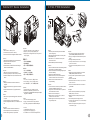
English /
1. Remove the 3.5” drive bay cover.
2. Insert the device into the 3.5” drive bay.
3. Insert the 3.5” HDD and tighten it with the screws.
Deutsch /
1. Entfernen Sie die Abdeckung des 3,5 Zoll Schachts.
2. Fügen Sie die Einheit in den 3,5 Zoll
Laufwerksschacht ein.
3. Führen Sie die 3,5 Zoll HDD ein und befestigen
Sie sie mit den Schrauben.
Français /
1. Retirez le couvercle de la baie de lecteur 3.5"
2. Insérez le périphérique 3.5" dans la baie pour lecteur.
3. Insérez le disque dur de 3,5" et sécurisez-le avec
les vis.
Español /
1. Extraiga la cubierta de la bahía de unidad de 3,5
pulgadas.
2. Coloque el dispositivo de 3,5 pulgadas en la bahía de
unidad.
3. Inserte el disco duro de 3,5” y apriételo con los
tornillos.
External 3.5” Device Installation 3.5” & 2.5” HDD Installation
12
Italiano /
1. Rimuovere il coperchio dell'alloggiamento dell'unità da
3,5 pollici
2. Inserire il dispositivo nel vano dell'unità da 3,5”.
3. Inserire il dispositivo HDD da 3,5” e fissarlo con le
viti.
Português/
1. Remova a cobertura da baía da unidade de 3,5”.
2. Insira o dispositivo na baía da unidade de 3,5”.
3. Insira o disco rígido de 3,5" e aparafuse.
Ελληνικά/
1. Αφαιρέστε το κάλυμμα της θέσης μονάδας 3,5”.
2. Εισάγετε τη συσκευή στη θέση μονάδας 3,5”.
3. Εισαγάγετε τον Σκληρό Δίσκο 3,5” και στερεώστε
τον με τις βίδες.
日本語 /
1. 3.5" ドライブベイのカバーを取り外します
2. デバイスを 3.5” ドライブベイに挿入します。
3. 3.5” HDDを挿入し、ねじで締め付けます。
Русский /
1. Снимите крышку 3,5 - дюймового отсека.
2. Вставьте 3,5-дюймовое устройство в отсек.
3. Установите 3,5-дюймовый жесткий диск и зафи
ксируйте его винтами.
简体中文 /
1. 卸下 3.5” 驱动器槽盖。
2. 将设备插入 3.5” 驱动器槽。
3. 插入3.5”硬盘并用螺丝锁上。
Türkçe /
1. 3.5” sürücü bölmesi kapağını çıkarın.
2. Aygıtı, 3.5” sürücü bölmesinin içine yerleştirin.
3. 3,5” HDD’yi yerleştirin ve vidalarla sabitleyin.
ภาษาไทย /
1. ถอดฝาปิดช่องไดรฟ์ขนาด 3.5” ออก
2. ใส่อุปกรณ์เข้าในช่องไดร์ฟขนาด 3.5”
3. ใส ่ HDD ขนาด 3.5” เข้าไปแล้วขันสกรูยึดให้แน่น
繁體中文 /
1. 移除3.5”擴充槽的擋板。
2. 插入硬體裝置。
3. 插入3.5”硬碟並用螺絲鎖上。
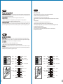
English /
1. Turn the keyhole of the front panel into the OPEN
position using the key.
2. Push and hold the release button on the front panel.
3. Pull the HDD tray out.
4. Place the 2.5” or 3.5” hard drive on the tray and
secure it with screws.
5. Slide the HDD tray back to the HDD cage.
Deutsch /
1. Drehen Sie das Schloss der Frontverkleidung mithilfe
des Schlüssels in die Position OFFEN
2. Drücken und halten Sie den Entriegelungsknopf auf
der Frontverkleidung.
3. Ziehen Sie den HD-Schacht heraus.
4. Montieren Sie die 2,5 oder 3,5 Zoll Festplatte im
Schacht und sichern Sie sie mit Schrauben.
5. Schieben Sie den Schacht wieder in den
Festplattenkäfig.
Français /
1. Tournez le trou de la serrure du panneau avant dans
la position OUVERTE en utilisant la clé.
2. Appuyez sur le bouton de libération sur le panneau
avant et maintenez-le enfoncé.
3. Enlevez le boîtier du disque dur.
4. Placez le disque dur de 2,5” ou de 3,5” dans le
boîtier et fixez-le avec des vis.
5. Refaites glisser le boîtier du disque dur dans la
cage de disques durs.
Español /
1. Gire el ojo de la cerradura del panel frontal a la
posición OPEN (ABIERTO) utilizando la llave.
2. Empuje y sostenga el botón de liberación del panel
frontal.
3. Extraiga la bandeja del disco duro.
4. Coloque el disco duro de 2’5 ó 3'5” en la bandeja y
fíjelo con los tornillos.
5. Vuelva a meter la bandeja del disco duro en su
hueco.
Italiano /
1. Ruotare il foro del pannello anteriore in posizione
OPEN (APERTO) utilizzando la chiave.
2. Tenere premuto il pulsante di rilascio sul panello
anteriore.
3. Estrarre il vano HDD.
4. Posizionare il disco fisso da 2,5” o 3,5” nel vano e
fissarlo con le viti.
5. Fare scorrere l’HDD indietro verso la struttura a
gabbia HDD.
Português /
1. Rode o orifício do painel dianteiro para a posição
OPEN (aberto), com a chave.
2. Mantenha premido o botão para abrir no painel
dianteiro.
3. Puxe a bandeja do disco rígido para fora.
4. Coloque o disco rígido de 2,5” ou 3,5” na bandeja e
fixe com parafusos.
5. Deslize a bandeja do disco rígido de volta para a
caixa do disco rígido.
2
2
4
3.5" HDD
2.5" HDD
藍色線條為尺寸標示,請勿印刷上去!
產品料號
VN10008W2N
L e v e l 1 0 G T B A T T L E
說明書 12/03/02 A
產品名稱
印刷項目
子件料號
發稿日期
版本
騎馬釘32 8 0 4
雙銅
157G
P X
書寫紙
單色 無無
其他特殊處理效果表面處理
2
厚度(g/m )
裝訂方式 材質頁數 印刷色彩
規格樣式
整本
MARKETING CHECK DESIGN
PRODUCT GM
其他特殊處理效果表面處理
2
厚度(g/m )
材質印刷色彩
封面樣式(當封面與內頁 樣式不 同時尚 須填寫)
Pei
刀模線
125 mm
176 mm
色
亮

13
EasySwap HDD Installation
14
Ελληνικά /
1. Στρέψτε την κλειδαριά του εμπρόσθιου πίνακα στη
θέση OPEN (ΑΝΟΙΧΤΟ) χρησιμοποιώντας το κλειδί.
2. Σπρώξτε και κρατήστε το κουμπί απασφάλισης στον
εμπρόσθιο πίνακα.
3. Τραβήξτε το δίσκο έξω HDD.
4. Τοποθετήστε το 2,5 "ή 3,5" σκληρό δίσκο στο δίσκο
και στερεώστε το με τις βίδες.
5. Σύρετε το HDD δίσκο πίσω στο κλουβί HDD
繁體中文 /
1. 用鑰匙將面板鎖孔轉至OPEN位置。
2. 按壓面板前方釋放鈕。
3. 將硬碟托盤取出
4. 將2.5”或3.5”硬碟放置在硬碟托盤上,用螺絲固定硬碟
5. 將硬碟托盤放回硬碟磁架中
简体中文 /
1. 用钥匙将面板锁孔转至OPEN位置。
2. 按压面板前方释放钮。
3. 将硬盘托盘取出
4. 将2.5”或3.5”硬盘放置在硬盘托盘上,用螺丝固定硬盘
5. 将硬盘托盘放回硬盘磁架中
日本語 /
1. かぎを使用し、前面パネルのかぎ穴を回して
OPEN(開く)位置にします。
2. 前面パネルの解除ボタンを押したままにします。
3.HDDトレイを引き出して外します。
4.2.5インチHDD、SSD もしくは 3.5インチHDDドラ
イブをトレイにネジで固定します。
5. HDDトレイをHDDケージに戻します。
Русский /
1. С помощью ключа поверните отверстие под ключ н
а передней панели в положение OPEN (ОТКРЫТО).
2. Нажмите и удерживайте кнопку освобождения
на передней панели.
3. Вытяните лоток для жестких дисков.
4. Установите 2,5- или 3,5-дюймовый жесткий диск
в лоток и закрепите его винтами.
5. Установите лоток для жестких дисков обратно в
каркас.
Türkçe /
1. Ön panelin anahtar deliğini, anahtarı kullanarak AÇIK
konumuna getirin.
2. Ön paneldeki serbest bırakma düğmesini basılı tutun.
3. HDD tepsisini dışarı çekin.
4. 2,5” veya 3,5” sabit disk sürücüsünü tepsinin
üzerine yerleştirin ve vidalarla sabitleyin.
5. HDD tepsisini HDD kafesine geri yerleştirin.
ภาษาไทย /
1. ใช้ลูกกุญแจไขรูกุญแจของแผงด้านหน้าไปที่ตำแหน่ง
OPEN (เปิด)
2. กดปุ่มปลดล็อคบนแผงด้านหน้าค้างไว้
3. ดึงถาด HDD ออกมา
4. วางฮาร์ดไดร์ฟขนาด 2.5” หรือ 3.5”
ลงบนถาดแล้วขันสกรูยึดให้แน่น
5. เลื่อนถาด HDD กลับเข้าในโครง HDD
English /
The Easy Swap slot is embedded to enable ultra fast
transfer (up to 3.0Gbps) of large data to a SATA hard disk
without having to use an external storage enclosure. To
ensure proper operation, please make sure the following
settings are correct:
1. Ensure all required drivers are installed for your
motherboard or SATA controller card.
2. Squeeze to pull the HDD tray out.
3. Mount the 3.5” HDD into the tray with screws provided.
4. Slide the HDD tray back to the HDD cage.
5. Connect the SATA cable to an available SATA
connector on the motherboard or SATA controller card.
6. Connect the power cable to power supply.
7. Ensure AHCI (Advanced Host Controller Interface) is
enabled on your motherboard or SATA controller card. The
AHCI enables for “hotswap” capability of the SATA hard
drives without having to turn off the computer prior to
connecting or disconnecting of the hard drive. Please
follow instruction provided by your motherboard or SATA
controller card to enable the AHCI function.
If you are using a brand new hard drive, the hard drive will
need to be initialized (formatted) before it is accessible.
For more information on how to initialize (format) a new
hard drive, please refer to the hard drive user manual or
visit
System running on Windows 7:
http://www.thermaltakeusa.com/Faq.aspx?ID=1143
System running on Windows Vista:
http://www.thermaltakeusa.com/Faq.aspx?ID=1079
System running on Windows XP:
http://www.thermaltakeusa.com/Faq.aspx?ID=1073
Deutsch /
Der Easy Swap-Einführungsschlitz st eingelassen, um einen
ultraschnellen Transfer (bis zu 3,0 GB/s) von umfangreichen
Daten zur SATA-Festplatte zu ermöglichen, ohne dafür ein
externes Gehäuse verwenden zu müssen. Um einen
ordnungsgemäßen Betrieb zu gewährleisten, stellen Sie bitte
sicher, dass die folgenden Einstellungen richtig sind:
1. Stellen Sie sicher, dass alle erforderlichen Treiber für Ihr
Mainboard oder SATA Controller-Karte installiert sind.
2. Drücken, um das HDD-Fach herauszuziehen.
3. Montieren Sie die 3,5" HDD mit den mitgelieferten
Schrauben in das Fach.
4. Schieben Sie den HDD-Schacht zurück in den HDD-Käfig.
5. Verbinden Sie das SATA-Kabel mit einen freien SATA-
Anschluss auf dem Mainboard oder der SATA Controller-
Karte.
6. Verbinden Sie das Stromkabel mit dem Netzteil.
7. Stellen Sie sicher, dass AHCI (Advanced Host Controller
Interface) auf dem Motherboard oder der SATA-Controller-
Karte aktiviert ist. AHCI ermöglicht die "HotSwap"-Funktion
der SATA-Festplatten, ohne dass Sie den Computer
ausschalten müssen, bevor Sie die Festplatte anschließen
oder entfernen. Bitte folgen Sie den Anweisungen Ihres
Motherboards oder der SATA-Controller-Karte, um die AHCI-
Funktion zu aktivieren.
Wenn Sie eine neue Festplatte benutzen, muss die Festplatte
initialisiert werden (formatiert), bevor sie nutzbar ist. Weitere
Informationen darüber, wie man eine neue Festplatte
formatiert, entnehmen Sie bitte dem Benutzerhandbuch zur
Festplatte oder besuchen Sie
System läuft unter Windows 7:
http://www.thermaltakeusa.com/Faq.aspx?ID=1143
System läuft unter Windows
Vista:http://www.thermaltakeusa.com/Faq.aspx?ID=1079
System läuft unter Windows XP:
http://www.thermaltakeusa.com/Faq.aspx?ID=1073
藍色線條為尺寸標示,請勿印刷上去!
產品料號
VN10008W2N
L e v e l 1 0 G T B A T T L E
說明書 12/03/02 A
產品名稱
印刷項目
子件料號
發稿日期
版本
騎馬釘32 8 0 4
雙銅
157G
P X
書寫紙
單色 無無
其他特殊處理效果表面處理
2
厚度(g/m )
裝訂方式 材質頁數 印刷色彩
規格樣式
整本
MARKETING CHECK DESIGN
PRODUCT GM
其他特殊處理效果表面處理
2
厚度(g/m )
材質印刷色彩
封面樣式(當封面與內頁 樣式不 同時尚 須填寫)
Pei
刀模線
125 mm
176 mm
色
亮
Seite wird geladen ...
Seite wird geladen ...
Seite wird geladen ...

22
ภาษาไทย /
1. การควบคุมไฟ LED – กดเพื่อสลับสีของไฟ LED
(สีน้ำเงิน, สีเขียว, สีแดง และไฟ LED
กระพริบหนึ่งครั้ง)
2. การควบคุมความเร็วของพัดลม –
กดเพื่อสลับเปลี่ยนความเร็วของพัดลม
Русский /Русский /
1. Переключатель светодиодной подсветки — н
ажмите, чтобы изменить цвет индикатора (си
ний, зеленый, красный и однократное мигани
е индикатора)
2. Регулятор скорости вентилятора — нажмите
для изменения скорости вращения.
Türkçe /
1. Işık Denetimi – Işıkların rengini değiştirmek
(Mavi, Yeşil, Kırmızı ve Tek Işığı Yanıp Sönen)
için düğmeye basın
2. Fan Hızı Denetimi – Fan hızını değiştirmek için
basın.
1
2
3
4
5
6
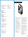
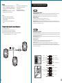
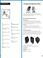
Fan Speed & Light Controller Connector Descriptions
① 4-pin peripheral connector
②,③,④ Fan power & signal connector (Front & Top)
⑤,⑥ Plug & Play fan power & signal connector (Side)
Note: Please ensure the Plug & Play connector is correctly connected with
corresponding electrode (i.e. + to + & - to - & S to S)
Leads Installation Guide
Leads Installation Guide
Case LED Connection / On the front of the case, you can find some LEDs and switch leads. Please consult your user
manual of your motherboard manufacturer, then connect these leads to the panel header on the motherboard.
USB 2.0 Connection / Please consult your motherboard manual to find out the section of “USB connection”.
USB 3.0 connection /
1. Make sure your motherboard supports internal USB 3.0 connection.
2. Connect the USB 3.0 cable to the available USB 3.0 port on your computer.
Audio Connection / Please refer to the following illustration of Audio connector and your motherboard user manual.
Please select the motherboard which used AC’97 or HD Audio(Azalia),(be aware of that your audio supports AC’97 or HD
Audio (Azalia)) or it will damage your device(s).
Anschlüsse herstellen
Gehäuse-LED-Verbindungen / Auf der Gehäusevorderseite finden Sie einige LEDs und Verbindungen. Bitte nehmen
Sie die Gebrauchsanweisung Ihres Motherboard Herstellers zur Hilfe und schließen Sie diese Verbindungen an die Panel
Header Belegung des Motherboards an.
USB 2.0 Anschluss / Bitte nehmen Sie die Gebrauchsanweisung Ihres Motherboards zur Hilfe und lesen Sie unter dem
Kapitel „USB Anschlüsse“ nach.
USB 3.0 Anschluss /
1. Stellen Sie sicher, dass Ihre Hauptplatine den internen USB 3.0 Anschluss unterstützt.
2. Verbinden Sie das USB 3.0 Kabel mit dem USB 3.0 Port auf Ihrem Computer.
Audio Anschlüsse / Bitte beachten Sie die folgende Abbildung der Audio Anschlüsse und die Anweisung in der
Gebrauchsanweisung Ihres Motherboards. Bitte wählen Sie das Motherboard, das AC’97 oder HD Audio(Azalia)
verwendet, (achten Sie darauf, dass Ihr Audio AC’97 bzw. HD Audio (Azalia unterstützt)). Andernfalls entstehen schwere
Schäden an Ihrem(n) Gerät(en)!!!
AUDIO AC'97 Function
GROUND
L-RET
R-RET
NC
BROWN
RED
MIC IN
MIC POWER
KEY
BLUE
NC
BLUE
L-OUT
YELLOW
R-OUT
BLACK
YELLOW
PRESENCE#
BLACK
SENSE1_RETURN
AUD GND
SENSE2_RETURN
YELLOW
BROWN
RED
PORT1 R
PORT2 R
PORT1 L
BLUE
PORT2 L
SENSE_SEND
KEY
PURPLE
GREEN
ORANGE
BLACK
AUDIO AZALIA Function
21
藍色線條為尺寸標示,請勿印刷上去!
產品料號
VN10008W2N
L e v e l 1 0 G T B A T T L E
說明書 12/03/02 A
產品名稱
印刷項目
子件料號
發稿日期
版本
騎馬釘32 8 0 4
雙銅
157G
P X
書寫紙
單色 無無
其他特殊處理效果表面處理
2
厚度(g/m )
裝訂方式 材質頁數 印刷色彩
規格樣式
整本
MARKETING CHECK DESIGN
PRODUCT GM
其他特殊處理效果表面處理
2
厚度(g/m )
材質印刷色彩
封面樣式(當封面與內頁 樣式不 同時尚 須填寫)
Pei
刀模線
125 mm
176 mm
色
亮
Seite wird geladen ...
Seite wird geladen ...
Seite wird geladen ...
Seite wird geladen ...
-
 1
1
-
 2
2
-
 3
3
-
 4
4
-
 5
5
-
 6
6
-
 7
7
-
 8
8
-
 9
9
-
 10
10
-
 11
11
-
 12
12
-
 13
13
-
 14
14
-
 15
15
-
 16
16


Thermaltake Level 10 GT Battle Edition Benutzerhandbuch
- Kategorie
- Computergehäuse
- Typ
- Benutzerhandbuch
in anderen Sprachen
- English: Thermaltake Level 10 GT Battle Edition User manual
- français: Thermaltake Level 10 GT Battle Edition Manuel utilisateur
- español: Thermaltake Level 10 GT Battle Edition Manual de usuario
- italiano: Thermaltake Level 10 GT Battle Edition Manuale utente
- русский: Thermaltake Level 10 GT Battle Edition Руководство пользователя
- português: Thermaltake Level 10 GT Battle Edition Manual do usuário
- 日本語: Thermaltake Level 10 GT Battle Edition ユーザーマニュアル
- Türkçe: Thermaltake Level 10 GT Battle Edition Kullanım kılavuzu
Verwandte Artikel
-
Thermaltake VO200M1W2N Benutzerhandbuch
-
-
Thermaltake Level 10 GTS Snow Edition Benutzerhandbuch
-
-
-
-
-
-
-
