
MPC01 Plus
Battery Management System
Installation and Operating Manual . . . . . . 8
Batteriemanagementsystem
Montage- und Bedienungsanleitung . . . 25
Système de gestion des batteries
Instructions de montage et de service . . 42
Sistema de gestión de baterías
Instrucciones de montaje y de uso . . . . .59
Sistema de gestão de baterias
Instruções de montagem e manual de
instruções . . . . . . . . . . . . . . . . . . . . . . . . . 76
Sistema di gestione batterie
Istruzioni di montaggio e d’uso . . . . . . . . 93
Accumanagementsysteem
Montagehandleiding en
gebruiksaanwijzing . . . . . . . . . . . . . . . . .110
Batterimanagementsystem
Monterings- og betjeningsvejledning . 127
Batterihanteringssystem
Monterings- och bruksanvisning. . . . . . 144
Batteristyringssystem
Monterings- og bruksanvisning . . . . . . .161
Akkuhallintajärjestelmä
Asennus- ja käyttöohje. . . . . . . . . . . . . . 178
Система управления батареями
Инструкция по монтажу
и эксплуатации. . . . . . . . . . . . . . . . . . . . 195
Układ zarządzania akumulatorami
Instrukcja montażu i obsługi . . . . . . . . . .211
Systém manažmentu batérií
Návod na montáž a uvedenie
do prevádzky . . . . . . . . . . . . . . . . . . . . . 228
Systém řízení a sledování stavu
akumulátoru
Návod k montáži a obsluze . . . . . . . . . . 245
Akkumulátorkezelő rendszer
Szerelési és használati útmutató . . . . . . 262
EN
DE
FR
ES
PT
IT
NL
DA
SV
NO
FI
RU
PL
SK
CS
HU
ENERGY & LIGHTING
CONTROLS
MPC01Plus-IO-16s.book Seite 1 Mittwoch, 6. Dezember 2017 7:16 19

MPC01Plus-IO-16s.book Seite 2 Mittwoch, 6. Dezember 2017 7:16 19

MPC01 Plus
3
1
2 43
5
9
15
12
13
14
8
7
6
11
10
16
17 18 19
1
MPC01Plus-IO-16s.book Seite 3 Mittwoch, 6. Dezember 2017 7:16 19

MPC01 Plus
4
1
3 4 5
2
2
AB
1 1
3
MPC01Plus-IO-16s.book Seite 4 Mittwoch, 6. Dezember 2017 7:16 19

MPC01 Plus
5
D+
Batt I
Batt II
F1
F2
F3
F4
F5 F6
F7
E3
E1
E2
E4
E5
E6
E7
E8
E9
E10
E11
E12
E13
E14
E15
E16
1
2
3
4
1
2
3
1
2
1
2
1
2
1
2
1
2
1
2
1
2
1
2
1
2
1
2
1
2
1
1
1
2
2
2
3
3
E17
1
2
CI-Bus
CI-Bus IBS B2A
IBS B2B
IBS B1
CI-Bus
CI-Bus
CI-Bus
17
18
19
16
1
2
3
4
5
7
6
10 11 1514131298
4
MPC01Plus-IO-16s.book Seite 5 Mittwoch, 6. Dezember 2017 7:16 19

MPC01 Plus
6
1
2
3
5
1
6
MPC01Plus-IO-16s.book Seite 6 Mittwoch, 6. Dezember 2017 7:16 19

MPC01 Plus
7
02:07:57
09:00 17.01.17
SW:Mar 10 2016
1
7
MPC01Plus-IO-16s.book Seite 7 Mittwoch, 6. Dezember 2017 7:16 19

Explanation of symbols MPC01 Plus
EN
8
Please read this instruction manual carefully before installation and first use, and store
it in a safe place. If you pass on the product to another person, hand over this instruc-
tion manual along with it.
Contents
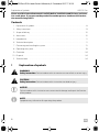
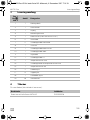
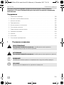
1 Explanation of symbols. . . . . . . . . . . . . . . . . . . . . . . . . . . . . . . . . . . . . . . . . . . . . . . . . . . . . . . 8
2 Safety instructions. . . . . . . . . . . . . . . . . . . . . . . . . . . . . . . . . . . . . . . . . . . . . . . . . . . . . . . . . . . 9
3 Scope of delivery . . . . . . . . . . . . . . . . . . . . . . . . . . . . . . . . . . . . . . . . . . . . . . . . . . . . . . . . . . 10
4 Accessories . . . . . . . . . . . . . . . . . . . . . . . . . . . . . . . . . . . . . . . . . . . . . . . . . . . . . . . . . . . . . . . 10
5 Intended use . . . . . . . . . . . . . . . . . . . . . . . . . . . . . . . . . . . . . . . . . . . . . . . . . . . . . . . . . . . . . . 11
6 Technical description . . . . . . . . . . . . . . . . . . . . . . . . . . . . . . . . . . . . . . . . . . . . . . . . . . . . . . . 11
7 Connecting and installing the system . . . . . . . . . . . . . . . . . . . . . . . . . . . . . . . . . . . . . . . . . . 13
8 Operating the system . . . . . . . . . . . . . . . . . . . . . . . . . . . . . . . . . . . . . . . . . . . . . . . . . . . . . . . 19
9 Guarantee . . . . . . . . . . . . . . . . . . . . . . . . . . . . . . . . . . . . . . . . . . . . . . . . . . . . . . . . . . . . . . . .24
10 Disposal. . . . . . . . . . . . . . . . . . . . . . . . . . . . . . . . . . . . . . . . . . . . . . . . . . . . . . . . . . . . . . . . . .24
11 Technical data. . . . . . . . . . . . . . . . . . . . . . . . . . . . . . . . . . . . . . . . . . . . . . . . . . . . . . . . . . . . .24
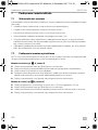
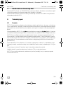
1 Explanation of symbols
!
!
A
I
WARNING!
Safety instruction: Failure to observe this instruction can cause fatal or serious injury.
CAUTION!
Safety instruction: Failure to observe this instruction can lead to injury.
NOTICE!
Failure to observe this instruction can cause material damage and impair the function
of the product.
NOTE
Supplementary information for operating the product.
MPC01Plus-IO-16s.book Seite 8 Mittwoch, 6. Dezember 2017 7:16 19

MPC01 Plus Safety instructions
EN
9
2 Safety instructions
The manufacturer accepts no liability for damage in the following cases:
• Damage to the product resulting from mechanical influences and excess voltage
• Alterations to the product without express permission from the manufacturer
• Use for purposes other than those described in the operating manual
Note the following basic safety information when using electrical devices to protect against:
• Electric shock
• Fire hazards
• Injury
!
WARNING!
• Electrical devices are not toys.
Always keep and use the device out of the reach of children.
• People (including children) whose physical, sensory or mental capacities or whose
lack of experience or knowledge prevent them from using this product safely should
not use it without the supervision or instruction of a responsible person.
• Only use the device as intended.
• Make sure that the lead has a sufficient cross-section.
• Lay the cables so that they cannot be damaged by the doors or the bonnet. Crushed
cables can lead to serious injury.
!
CAUTION!
• Lay the cables so that they cannot be tripped over or damaged.
• Do not operate the device
– In salty, wet or damp environments
– In the vicinity of corrosive fumes
– In areas where there is a danger of explosions
• Always disconnect the power supply when working on the device.
• Please observe that parts of the device may still conduct voltage even if the fuse has
blown.
• Do not disconnect any cables when the device is still in use.
A
NOTICE!
• Use ductwork or cable ducts if it is necessary to lay cables through metal panels or
other panels with sharp edges.
• Do not lay the cable so that it is loose or heavily kinked.
• Fasten the cables securely.
• Do not pull on the cables.
MPC01Plus-IO-16s.book Seite 9 Mittwoch, 6. Dezember 2017 7:16 19

Scope of delivery MPC01 Plus
EN
10
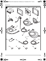
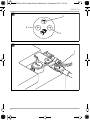
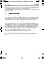
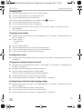
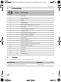
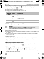
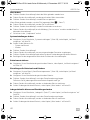
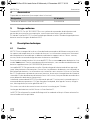
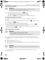
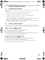
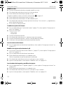
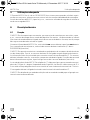
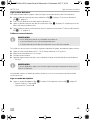
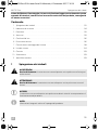
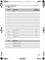
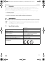
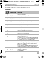
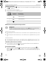
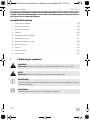
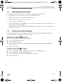
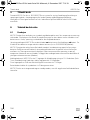
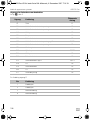
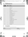
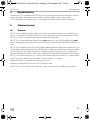
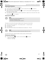
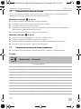
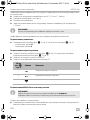
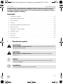
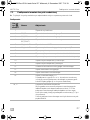
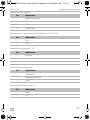
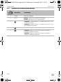
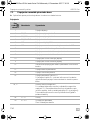
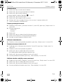
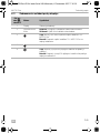
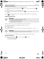
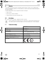
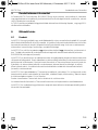
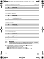
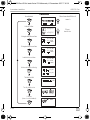
3Scope of delivery
4 Accessories
Available as accessories (not included in the scope of delivery):
No. in
fig. 1,
page 3
Quantity Description
11Switchbox
21Cover frame
31Display
4 1 Assembly frame
5 1 Battery sensor (Hella Sensor MCA-HS1)
62Tank probe
7 2 Tank probe connection cable
81Step button
9 1 Battery sensor connection cable
10 1 Battery charger connection cable
11 1 Control cable
12 1 Connection cable D+
13 1 Internal temperature sensor
14 1 Internal temperature sensor connection cable
15 1 External temperature sensor
16 3 2-series bushing
17 13 3-series bushing
18 1 4-series bushing
19 39 Plug-in contacts
Description Ref. no.
Battery sensor, MCA-HS1 Hella sensor 9102500038
MPC01Plus-IO-16s.book Seite 10 Mittwoch, 6. Dezember 2017 7:16 19

MPC01 Plus Intended use
EN
11
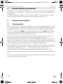
5Intended use
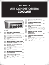
Dometic MPC01 Plus (ref. no. 9102500075) is a system for the control, distribution and manage-
ment of voltages in mobile homes, caravans or other extension vehicles.
The CI-BUS interface can typically be used to monitor the charge status of multiple batteries or an
MCA battery charger.
6 Technical description
6.1 Function
MPC01 Plus consists of a display, a control box and accessory parts such as temperature sensors
and tank probes. The current status information for each battery connected via a battery sensor
appears on the display: Current, voltage, remaining charge time of all connected batteries.
Included with the MPC01 Plus is one battery sensor for connecting one battery. To connect more
batteries you need additional battery sensors (item no. 9102500038) (accessories).
MPC01 Plus enables the charge status of the starter battery and up to two supply batteries to be
monitored. To do so, the battery sensors are connected to the negative pole of the batteries. The
information read out from them is transmitted to the display via the CI bus interface. The battery
sensors measure the voltage, current and temperature of the connected battery. Along with the
battery sensor supplied, up to two more battery sensors (accessories) can be connected.
The control box of the MPC01 Plus has 17 outputs for connection and control of 12 V consumer
units (e.g. step, tent light, refrigerator, side light) and universal 12 V outputs.
These outputs are protected against short circuit or overcurrent via 7 fuses.
The battery charger is connected to the control box via the CI bus interface.
MPC01 Plus features a display mode, and a stand-by mode which is activated after a preset
interval.
MPC01Plus-IO-16s.book Seite 11 Mittwoch, 6. Dezember 2017 7:16 19

Technical description MPC01 Plus
EN
12
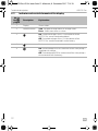
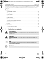
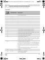
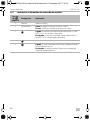
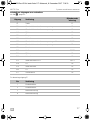
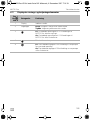
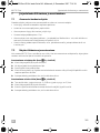
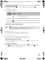
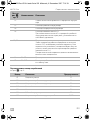
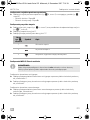
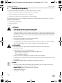
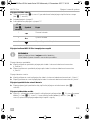
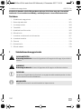
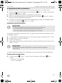
6.2 Indicator and control elements of the display
No. in
fig. 2,
page 4
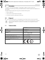
Description Explanation
1Display Shows values
2 Selector button Tu rn : Navigate through menus or change values
Press: Select menu items or values
3 On: Switched voltages of the 12 V distribution of the
MPC01 Plus are activated and enabled.
Off: Switched voltages of the 12 V distribution of the
MPC01 Plus are disconnected from the battery.
4Back to main menu
5 On: Switched output E5 for connection of the water pump is
supplied with voltage.
Off: Switched output E5 for connection of the water pump is
disconnected from the battery
MPC01Plus-IO-16s.book Seite 12 Mittwoch, 6. Dezember 2017 7:16 19

MPC01 Plus Connecting and installing the system
EN
13
7 Connecting and installing the system
7.1 Notes on installation
When selecting the installation location for the display and control box, observe the following
instructions:
• The device must be installed in a location that is protected from moisture.
• Do not install the device in a dusty environment.
• The device must be installed on a level and sufficiently sturdy surface.
• Consider the control cable‘s length of 12 m.
• Install the control box in a well-protected location, close to the batteries if possible, to ensure
no objects can touch the connection cable and cause it to tear.
• Secure the connected cables using suitable fittings, e.g. cable clamps, to ensure the plug
cannot be torn from the circuit board.
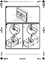
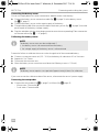
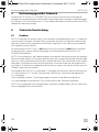
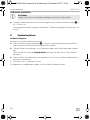
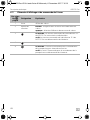
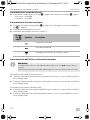
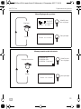
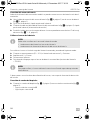
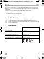
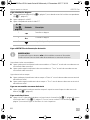
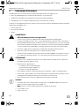
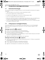
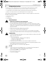
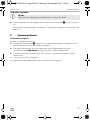
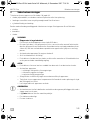
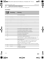
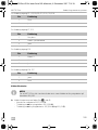
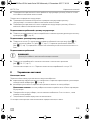
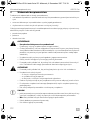
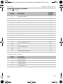
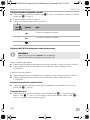
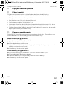
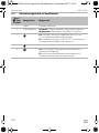
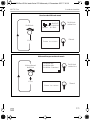
7.2 Connecting and installing the display
You can install the MPC01 Plus on the wall or in the wall. For installation on the wall, the control
cable can either be guided through the wall or affixed on the wall.
Installing the display on a wall (fig. 3 A, page 4)
➤ Plug the control cable (1) into the connection on the display.
➤ Guide the control cable through the installation frame.
➤ Place the display in the installation frame.
➤ Affix the installation frame and display insert onto a suitable part of the wall using the four long
screws supplied.
➤ Attach the cover frame so that it latches into place.
Installing the display in a wall (fig. 3 A, page 4)
➤ Prepare a recess in the wall measuring 11 x 9.9 cm and which is 2.5 cm in depth.
➤ Plug the control cable (1) into the connection on the display.
➤ Affix the display using the four short screws supplied.
➤ Attach the cover frame so that it latches into place.
MPC01Plus-IO-16s.book Seite 13 Mittwoch, 6. Dezember 2017 7:16 19

Connecting and installing the system MPC01 Plus
EN
14
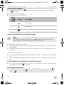
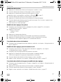
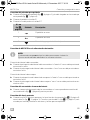
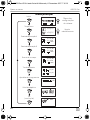
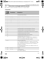
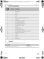
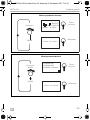
7.3 Connecting and installing the control box
➤ Screw the control box in place at a suitable location using four screws.
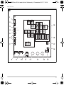
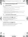
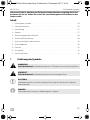
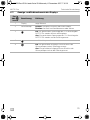
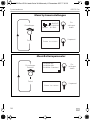
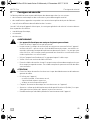
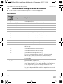
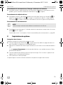
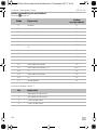
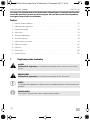
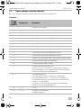
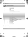
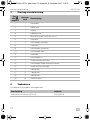
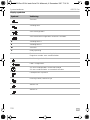
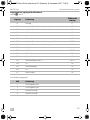
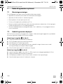
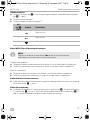
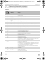
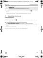
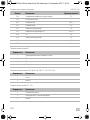
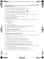
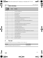
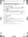
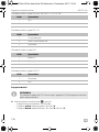
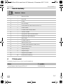
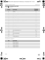
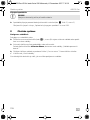
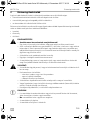
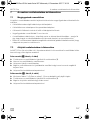
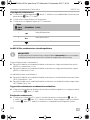
Connections
No. in
fig. 4,
page 5
Description Explanation
1Connection for display
2 IBS_B1 Connection for supply battery B
3 IBS_B2B Connection for supply battery A
4 IBS_B2A CI bus Connection for starter battery
5 CI bus Connection for MCA chargers
6 CI bus Connection for devices communicating with the CI bus
7 Connection for step button
8 Connection for waste water tank probe
9 Connection for fresh water tank probe
10 Connection for external temperature sensor
11 Connection for internal temperature sensor
12 Earth connection for consumer unit and starter battery
13 Connection for consumer unit battery
14 Connection for starter battery
15 Connection for side light and D+
When connecting the D+ signal, the starter and consumer
unit battery (amongst other units) are interconnected via a
relay on the board of the control box.
16, 17 Compressor wire bridge
If a wire bridge is set, the refrigerator is permanently
supplied with 12 V voltage. Without a wire bridge, the
refrigerator is only supplied with voltage if the vehicle is in
operation (D+ is applied).
The cross section of the wire bridge must be designed
corresponding to the current of the refrigerator.
18 F1 – F7 Fuses
19 E1 – E17 Outputs for consumer units
See following table
MPC01Plus-IO-16s.book Seite 14 Mittwoch, 6. Dezember 2017 7:16 19

MPC01 Plus Connecting and installing the system
EN
15
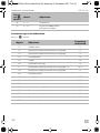
Switchable outputs for consumer units
see fig. 4, page 5
Pin assignment output E1
Output Explanation Associated fuse
E1 Step F1
E2 Connected consumer unit battery voltage F3
E3 Connected consumer unit battery voltage F2
E4 Side light F5
E5 Pump F4
E6 Consumer unit battery F5
E7 Connected consumer unit battery voltage and D+ F4/F3
E8 Connected consumer unit battery voltage F2
E9 Not assigned
E10 Refrigerator F5/F7
E11 Side light F5
E12 Consumer unit battery F5
E13 Consumer unit battery and D+ F4/F3
E14 D+ F4
E15 Consumer unit battery F5
E16 D+ F4
E17 Tent light F4
Pin Explanation
1 Limit switch
2 Limit switch
3 Engine connection
4 Engine connection
MPC01Plus-IO-16s.book Seite 15 Mittwoch, 6. Dezember 2017 7:16 19

Connecting and installing the system MPC01 Plus
EN
16
Pin assignment output E2 to E6, E8, E9, E11, E12, E15, E16
Pin assignment output E7, E13
Pin assignment output E10
Pin assignment output E14, E17
Connecting the batteries
I
➤ Connect the batteries as follows (fig. 4, page 5):
– Connection for starter battery: IBS_B2A (3)
–Connecting one supply battery: IBS_B2B (4)
–Connecting two supply batteries: IBS_B2A (4) and IBS_B1 (2)
Pin Explanation
1Plus
2Earth
Pin Explanation
1 continuous positive
2Battery2 to main relay
3Earth
Pin Explanation
1Battery2
2Connected positive terminal
3Earth
Pin Explanation
1Earth
2Plus
NOTE
To enable MPC01 Plus to display data, a supply battery must be connected to at least
the output IBS_B2B.
MPC01Plus-IO-16s.book Seite 16 Mittwoch, 6. Dezember 2017 7:16 19

MPC01 Plus Connecting and installing the system
EN
17
Connecting the battery sensor
One or two supply batteries can be connected in addition to the starter battery.
➤ Connect the battery sensor connection cable (fig. 1 8, page 3) to the battery sensor
(fig. 1 5, page 3).
➤ Connect the battery sensor to the negative pole of the battery.
➤ Clamp the blue cable of the connection cable of the battery sensor (fig. 1 8, page 3) onto the
positive pole of the battery (voltage supply).
➤ Plug the red cable with the white plug connection onto the corresponding CI bus connection
on the control box (fig. 4 1 – 6, page 5).
Calibrating the battery sensor
I
Proceed as follows to calibrate the sensor to the charge level of the connected battery:
➤ Connect a strong consumer unit (20 – 30 A) to the battery for a duration of 3 to 5 minutes.
➤ Repeat this 2 to 3 times.
➤ Disconnect the consumer unit.
➤ Allow the battery sensor some time to calibrate itself (battery current < 100 mA).
I
If you want to reset the calibration data of the sensor, disconnect the sensor's power supply.
Connecting the tank probes
➤ Connect the tank probes (fig. 1 6, page 3) as follows (fig. 4, page 5):
– Waste water: Connection 8
– Fresh water: Connection 9
NOTE
The battery sensor must now be recalibrated, if
• the battery sensor is disconnected from the battery
• the voltage supply of the battery sensor is disconnected
NOTE
The battery sensor requires a rest period of approximately 8 hours for calibration.
MPC01Plus-IO-16s.book Seite 17 Mittwoch, 6. Dezember 2017 7:16 19

Connecting and installing the system MPC01 Plus
EN
18
Connecting the step button
➤ Connect the step button (fig. 1 8, page 3) and extension cable to the associated input
(fig. 4 7, page 5).
➤ Connect the step to output E1.
➤ Connect the tent light to output E17.
Connecting the MPC01 Plus to the voltage supply
I
Connecting the consumer unit battery:
➤ Connect the positive terminal of the consumer unit battery to “Battery II” using a cable with a
ring cable lug.
➤ Connect the negative terminal of the consumer unit battery to “Earth” using a cable with a ring
cable lug.
Connecting the starter battery:
➤ Connect the positive terminal of the starter battery to “Battery I” using a cable with a ring cable
lug.
➤ Connect the negative terminal of the starter battery to “Earth” using a cable with a ring cable
lug.
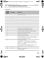
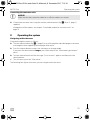
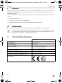
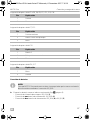
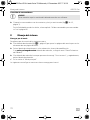
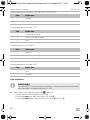
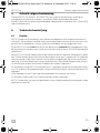
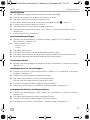
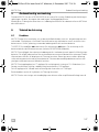
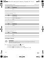
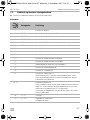
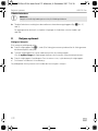
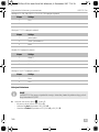
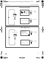
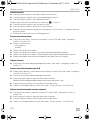
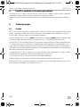
Connecting power consuming devices to the battery sensor
➤ Always connect the negative pole of the power consuming devices to the correct connection
on the battery sensor (fig. 6 1, page 6).
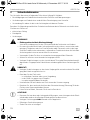
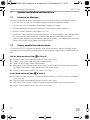
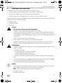
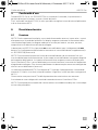
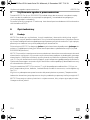
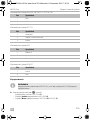
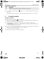
Connecting the base vehicle
➤ Connect the D+ signal of the base vehicle and the side lights to the connection (fig. 4 15,
page 5) using the D+ cable (fig. 1 12, page 3). For this, cut through the centre of the D+
cable (fig. 1 12, page 3) supplied and connect the corresponding voltages and signals.
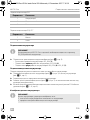
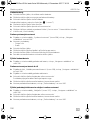
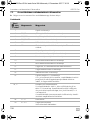
No. in
fig. 5,
page 6
Symbol Description
1 Retract step
2 Extend step
3 Switch tent light on/off
NOTE
The cables for connecting the batteries are not included in the scope of delivery.
Select a cable cross section suitable for the maximum currents.
MPC01Plus-IO-16s.book Seite 18 Mittwoch, 6. Dezember 2017 7:16 19

MPC01 Plus Operating the system
EN
19
Connecting the consumer units:
A
➤ Connect the consumer units using the contacts and connectors (fig. 1 18 to 21, page 3)
supplied.
Intended use of the outputs: see chapter “Switchable outputs for consumer units” on
page 15.
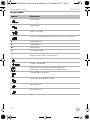
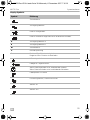
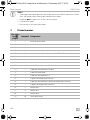
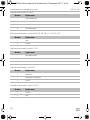
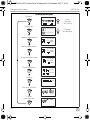
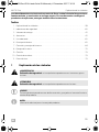
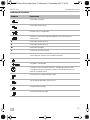
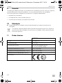
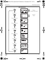
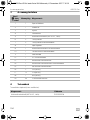
8 Operating the system
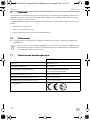
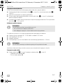
Navigating within the menu
Navigate through the menus as follows:
➤ Turn the selector button (fig. 2 2, page 4) to scroll through the individual pages in the menu
or through the items appearing on one page of the menu.
➤ Press the selector button to access the sub-menus or change mode.
If you press the selector button longer, you will be taken to the “Menu battery parameters”
menu.
➤ Turn the selector button until the message “Press to return” appears and then press the
selector button.
✓ This will return you to the “Main menu”.
The following four figures show how you can navigate within the menu.
NOTICE!
Make sure that the connection cable has a sufficient cable cross section.
MPC01Plus-IO-16s.book Seite 19 Mittwoch, 6. Dezember 2017 7:16 19

Operating the system MPC01 Plus
EN
20
1.
0,0A
U: 14,0V
I: -5mA
>100h
14,0V
14,0V
U: 14,0V
I: -5mA
A
>100h
U: 14,0V
I: -5mA
B
>100h
15:35:32 16.05.16
°C
°C
+21,5°C
+21,5°C
000%
2 s
Main menu
System
settings menu
Charger
Starter battery
Start
Supply battery B
Supply battery A
Battery voltage
Temperature
Lamp
(no function assigned)
Set offset
Tank level
MPC01Plus-IO-16s.book Seite 20 Mittwoch, 6. Dezember 2017 7:16 19
Seite wird geladen ...
Seite wird geladen ...
Seite wird geladen ...
Seite wird geladen ...
Seite wird geladen ...
Seite wird geladen ...
Seite wird geladen ...
Seite wird geladen ...
Seite wird geladen ...
Seite wird geladen ...
Seite wird geladen ...
Seite wird geladen ...
Seite wird geladen ...
Seite wird geladen ...
Seite wird geladen ...
Seite wird geladen ...
Seite wird geladen ...
Seite wird geladen ...
Seite wird geladen ...
Seite wird geladen ...
Seite wird geladen ...
Seite wird geladen ...
Seite wird geladen ...
Seite wird geladen ...
Seite wird geladen ...
Seite wird geladen ...
Seite wird geladen ...
Seite wird geladen ...
Seite wird geladen ...
Seite wird geladen ...
Seite wird geladen ...
Seite wird geladen ...
Seite wird geladen ...
Seite wird geladen ...
Seite wird geladen ...
Seite wird geladen ...
Seite wird geladen ...
Seite wird geladen ...
Seite wird geladen ...
Seite wird geladen ...
Seite wird geladen ...
Seite wird geladen ...
Seite wird geladen ...
Seite wird geladen ...
Seite wird geladen ...
Seite wird geladen ...
Seite wird geladen ...
Seite wird geladen ...
Seite wird geladen ...
Seite wird geladen ...
Seite wird geladen ...
Seite wird geladen ...
Seite wird geladen ...
Seite wird geladen ...
Seite wird geladen ...
Seite wird geladen ...
Seite wird geladen ...
Seite wird geladen ...
Seite wird geladen ...
Seite wird geladen ...
Seite wird geladen ...
Seite wird geladen ...
Seite wird geladen ...
Seite wird geladen ...
Seite wird geladen ...
Seite wird geladen ...
Seite wird geladen ...
Seite wird geladen ...
Seite wird geladen ...
Seite wird geladen ...
Seite wird geladen ...
Seite wird geladen ...
Seite wird geladen ...
Seite wird geladen ...
Seite wird geladen ...
Seite wird geladen ...
Seite wird geladen ...
Seite wird geladen ...
Seite wird geladen ...
Seite wird geladen ...
Seite wird geladen ...
Seite wird geladen ...
Seite wird geladen ...
Seite wird geladen ...
Seite wird geladen ...
Seite wird geladen ...
Seite wird geladen ...
Seite wird geladen ...
Seite wird geladen ...
Seite wird geladen ...
Seite wird geladen ...
Seite wird geladen ...
Seite wird geladen ...
Seite wird geladen ...
Seite wird geladen ...
Seite wird geladen ...
Seite wird geladen ...
Seite wird geladen ...
Seite wird geladen ...
Seite wird geladen ...
Seite wird geladen ...
Seite wird geladen ...
Seite wird geladen ...
Seite wird geladen ...
Seite wird geladen ...
Seite wird geladen ...
Seite wird geladen ...
Seite wird geladen ...
Seite wird geladen ...
Seite wird geladen ...
Seite wird geladen ...
Seite wird geladen ...
Seite wird geladen ...
Seite wird geladen ...
Seite wird geladen ...
Seite wird geladen ...
Seite wird geladen ...
Seite wird geladen ...
Seite wird geladen ...
Seite wird geladen ...
Seite wird geladen ...
Seite wird geladen ...
Seite wird geladen ...
Seite wird geladen ...
Seite wird geladen ...
Seite wird geladen ...
Seite wird geladen ...
Seite wird geladen ...
Seite wird geladen ...
Seite wird geladen ...
Seite wird geladen ...
Seite wird geladen ...
Seite wird geladen ...
Seite wird geladen ...
Seite wird geladen ...
Seite wird geladen ...
Seite wird geladen ...
Seite wird geladen ...
Seite wird geladen ...
Seite wird geladen ...
Seite wird geladen ...
Seite wird geladen ...
Seite wird geladen ...
Seite wird geladen ...
Seite wird geladen ...
Seite wird geladen ...
Seite wird geladen ...
Seite wird geladen ...
Seite wird geladen ...
Seite wird geladen ...
Seite wird geladen ...
Seite wird geladen ...
Seite wird geladen ...
Seite wird geladen ...
Seite wird geladen ...
Seite wird geladen ...
Seite wird geladen ...
Seite wird geladen ...
Seite wird geladen ...
Seite wird geladen ...
Seite wird geladen ...
Seite wird geladen ...
Seite wird geladen ...
Seite wird geladen ...
Seite wird geladen ...
Seite wird geladen ...
Seite wird geladen ...
Seite wird geladen ...
Seite wird geladen ...
Seite wird geladen ...
Seite wird geladen ...
Seite wird geladen ...
Seite wird geladen ...
Seite wird geladen ...
Seite wird geladen ...
Seite wird geladen ...
Seite wird geladen ...
Seite wird geladen ...
Seite wird geladen ...
Seite wird geladen ...
Seite wird geladen ...
Seite wird geladen ...
Seite wird geladen ...
Seite wird geladen ...
Seite wird geladen ...
Seite wird geladen ...
Seite wird geladen ...
Seite wird geladen ...
Seite wird geladen ...
Seite wird geladen ...
Seite wird geladen ...
Seite wird geladen ...
Seite wird geladen ...
Seite wird geladen ...
Seite wird geladen ...
Seite wird geladen ...
Seite wird geladen ...
Seite wird geladen ...
Seite wird geladen ...
Seite wird geladen ...
Seite wird geladen ...
Seite wird geladen ...
Seite wird geladen ...
Seite wird geladen ...
Seite wird geladen ...
Seite wird geladen ...
Seite wird geladen ...
Seite wird geladen ...
Seite wird geladen ...
Seite wird geladen ...
Seite wird geladen ...
Seite wird geladen ...
Seite wird geladen ...
Seite wird geladen ...
Seite wird geladen ...
Seite wird geladen ...
Seite wird geladen ...
Seite wird geladen ...
Seite wird geladen ...
Seite wird geladen ...
Seite wird geladen ...
Seite wird geladen ...
Seite wird geladen ...
Seite wird geladen ...
Seite wird geladen ...
Seite wird geladen ...
Seite wird geladen ...
Seite wird geladen ...
Seite wird geladen ...
Seite wird geladen ...
Seite wird geladen ...
Seite wird geladen ...
Seite wird geladen ...
Seite wird geladen ...
Seite wird geladen ...
Seite wird geladen ...
Seite wird geladen ...
Seite wird geladen ...
Seite wird geladen ...
Seite wird geladen ...
Seite wird geladen ...
Seite wird geladen ...
Seite wird geladen ...
Seite wird geladen ...
Seite wird geladen ...
Seite wird geladen ...
Seite wird geladen ...
Seite wird geladen ...
Seite wird geladen ...
Seite wird geladen ...
Seite wird geladen ...
Seite wird geladen ...
Seite wird geladen ...
Seite wird geladen ...
Seite wird geladen ...
Seite wird geladen ...
Seite wird geladen ...
Seite wird geladen ...
Seite wird geladen ...
Seite wird geladen ...
-
 1
1
-
 2
2
-
 3
3
-
 4
4
-
 5
5
-
 6
6
-
 7
7
-
 8
8
-
 9
9
-
 10
10
-
 11
11
-
 12
12
-
 13
13
-
 14
14
-
 15
15
-
 16
16
-
 17
17
-
 18
18
-
 19
19
-
 20
20
-
 21
21
-
 22
22
-
 23
23
-
 24
24
-
 25
25
-
 26
26
-
 27
27
-
 28
28
-
 29
29
-
 30
30
-
 31
31
-
 32
32
-
 33
33
-
 34
34
-
 35
35
-
 36
36
-
 37
37
-
 38
38
-
 39
39
-
 40
40
-
 41
41
-
 42
42
-
 43
43
-
 44
44
-
 45
45
-
 46
46
-
 47
47
-
 48
48
-
 49
49
-
 50
50
-
 51
51
-
 52
52
-
 53
53
-
 54
54
-
 55
55
-
 56
56
-
 57
57
-
 58
58
-
 59
59
-
 60
60
-
 61
61
-
 62
62
-
 63
63
-
 64
64
-
 65
65
-
 66
66
-
 67
67
-
 68
68
-
 69
69
-
 70
70
-
 71
71
-
 72
72
-
 73
73
-
 74
74
-
 75
75
-
 76
76
-
 77
77
-
 78
78
-
 79
79
-
 80
80
-
 81
81
-
 82
82
-
 83
83
-
 84
84
-
 85
85
-
 86
86
-
 87
87
-
 88
88
-
 89
89
-
 90
90
-
 91
91
-
 92
92
-
 93
93
-
 94
94
-
 95
95
-
 96
96
-
 97
97
-
 98
98
-
 99
99
-
 100
100
-
 101
101
-
 102
102
-
 103
103
-
 104
104
-
 105
105
-
 106
106
-
 107
107
-
 108
108
-
 109
109
-
 110
110
-
 111
111
-
 112
112
-
 113
113
-
 114
114
-
 115
115
-
 116
116
-
 117
117
-
 118
118
-
 119
119
-
 120
120
-
 121
121
-
 122
122
-
 123
123
-
 124
124
-
 125
125
-
 126
126
-
 127
127
-
 128
128
-
 129
129
-
 130
130
-
 131
131
-
 132
132
-
 133
133
-
 134
134
-
 135
135
-
 136
136
-
 137
137
-
 138
138
-
 139
139
-
 140
140
-
 141
141
-
 142
142
-
 143
143
-
 144
144
-
 145
145
-
 146
146
-
 147
147
-
 148
148
-
 149
149
-
 150
150
-
 151
151
-
 152
152
-
 153
153
-
 154
154
-
 155
155
-
 156
156
-
 157
157
-
 158
158
-
 159
159
-
 160
160
-
 161
161
-
 162
162
-
 163
163
-
 164
164
-
 165
165
-
 166
166
-
 167
167
-
 168
168
-
 169
169
-
 170
170
-
 171
171
-
 172
172
-
 173
173
-
 174
174
-
 175
175
-
 176
176
-
 177
177
-
 178
178
-
 179
179
-
 180
180
-
 181
181
-
 182
182
-
 183
183
-
 184
184
-
 185
185
-
 186
186
-
 187
187
-
 188
188
-
 189
189
-
 190
190
-
 191
191
-
 192
192
-
 193
193
-
 194
194
-
 195
195
-
 196
196
-
 197
197
-
 198
198
-
 199
199
-
 200
200
-
 201
201
-
 202
202
-
 203
203
-
 204
204
-
 205
205
-
 206
206
-
 207
207
-
 208
208
-
 209
209
-
 210
210
-
 211
211
-
 212
212
-
 213
213
-
 214
214
-
 215
215
-
 216
216
-
 217
217
-
 218
218
-
 219
219
-
 220
220
-
 221
221
-
 222
222
-
 223
223
-
 224
224
-
 225
225
-
 226
226
-
 227
227
-
 228
228
-
 229
229
-
 230
230
-
 231
231
-
 232
232
-
 233
233
-
 234
234
-
 235
235
-
 236
236
-
 237
237
-
 238
238
-
 239
239
-
 240
240
-
 241
241
-
 242
242
-
 243
243
-
 244
244
-
 245
245
-
 246
246
-
 247
247
-
 248
248
-
 249
249
-
 250
250
-
 251
251
-
 252
252
-
 253
253
-
 254
254
-
 255
255
-
 256
256
-
 257
257
-
 258
258
-
 259
259
-
 260
260
-
 261
261
-
 262
262
-
 263
263
-
 264
264
-
 265
265
-
 266
266
-
 267
267
-
 268
268
-
 269
269
-
 270
270
-
 271
271
-
 272
272
-
 273
273
-
 274
274
-
 275
275
-
 276
276
-
 277
277
-
 278
278
-
 279
279
-
 280
280


Dometic MPC01Plus Bedienungsanleitung
- Typ
- Bedienungsanleitung
- Dieses Handbuch eignet sich auch für
in anderen Sprachen
- français: Dometic MPC01Plus Mode d'emploi
- italiano: Dometic MPC01Plus Istruzioni per l'uso
- slovenčina: Dometic MPC01Plus Návod na používanie
- dansk: Dometic MPC01Plus Betjeningsvejledning
Verwandte Artikel
-
Dometic MPC01 Bedienungsanleitung
-
Dometic MCA1215, MCA1225, MCA1235, MCA1250, MCA1280, MCA2415, MCA2425, MCA2440 Benutzerhandbuch
-
Dometic eStore Bedienungsanleitung
-
-
-
-
-
-
 Domestic COOLAIR SP 950I Installationsanleitung
-
Dometic CoolAir RT780 Installationsanleitung

