
Weather Station · Wetterstation · Station météo · Weerstation · Estación meteorológica ·
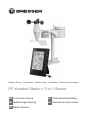
PC Weather Station + 5-in-1 Sensor
EN Instruction manual
DE Bedienungsanleitung
FR Mode d’emploi
NL Gebruikershandleiding
ES Manual de instrucciones

DE
Besuchen Sie unsere Website über den folgenden QR Code oder Weblink um weitere Informationen
zu diesem Produkt oder die verfügbaren Übersetzungen dieser Anleitung zu finden.
EN
Visit our website via the following QR Code or web link to find further information on this product or
the available translations of these instructions.
FR
Si vous souhaitez obtenir plus d’informations concernant ce produit ou rechercher ce mode
d’emploi en d’autres langues, rendez-vous sur notre site Internet en utilisant le code QR ou le lien
correspondant.
NL
Bezoek onze internetpagina via de volgende QR-code of weblink, voor meer informatie over dit
product of de beschikbare vertalingen van deze gebruiksaanwijzing.
ES
¿Desearía recibir unas instrucciones de uso completas sobre este producto en un idioma determinado?
Entonces visite nuestra página web utilizando el siguiente enlace (código QR) para ver las versioneAs
disponibles.
IT
Desidera ricevere informazioni esaustive su questo prodotto in una lingua specifica? Venga a
visitare il nostro sito Web al seguente link (codice QR Code) per conoscere le versioni disponibili.
www.bresser.de/P7002571
www.bresser.de/warranty_terms
GARANTIE · WARRANTY · GARANTÍA · GARANZIA

English...................................................................................................................
4
Deutsch .................................................................................................................
14
Français.................................................................................................................
24
Nederlands ...........................................................................................................
34
Español..................................................................................................................
44

4 / 56
1 Imprint
Bresser GmbH
Gutenbergstr. 2
46414 Rhede
Germany
http://www.bresser.de
If you wish to submit a warranty claim or service request, please refer to the “Warranty” and “Service”
information in this document. Please be aware that any requests or submissions sent directly to the
manufacturer cannot be processed.
Errors excepted. Subject to technical modifications.
© 2019 Bresser GmbH
All rights reserved.
Reproduction of this document, including extracts, in any form (photocopied, printed etc.) or the use
and distribution of this document by electronic means (image file, website etc.) is not permitted without
the prior written consent of the manufacturer.
The terms and brand names of the respective companies used in this document are protected by
brand, patent or product law in Germany, the European Union and/or other countries.
2 Validity information
This documentation is valid for the products with the article numbers listed below:
7002571
Manual version: 1019
Manual description:
Quickstart_7002571_PC-Weather-Station_en-de-fr-nl-es_BRESSER_v102019a
With any service inquiries, please state these information.
3 About this Instruction Manual
NOTICE
These operating instructions are to be considered a component of the device.
Please read the safety instructions and the operating instructions carefully before use.
Keep these instructions for renewed use at a later date. When the device is sold or given to someone
else, the instruction manual must be provided to the new owner/user of the product.
4 General safety instructions
DANGER
Risk of suffocation
Improper use of this product can result in suffocation. This is particularly dangerous for children. The
following safety information must be observed at all times.
• Keep packaging materials (plastic bags, rubber bands etc.) away from children. They can cause
suffocation.
• This product contains small parts that could be swallowed by children. There is a risk of choking!

5 / 56
DANGER
Risk of electric shock
This device has electronic parts operated via a power source (power supply and/or batteries). Im-
proper use of this product can cause an electric shock. An electric shock can cause serious or poten-
tially fatal injuries. The following safety information must be observed at all times.
• Children must only use the device under adult supervision! Only use the device as described in the
manual; otherwise, you run the risk of an electric shock.
DANGER
Risk of explosion
Improper use of this product can cause an explosion. The following safety information must be ob-
served at all times to prevent an explosion.
• Do not expose the device to high temperatures. Use only the recommended batteries. Do not
short-circuit the device or batteries, or throw them into a fire! Excessive heat or improper handling
could trigger a short-circuit, a fire or an explosion!
NOTICE
Risk of damage to property
Improper handling can result in damage to the device and/or to the accessories. Always observe the
following safety information when using the device.
• Never disassemble the device. In the event of a fault, please contact your specialist retailer. The
specialist retailer will contact the service centre and send the device for repair if necessary.
• Do not immerse the unit in water!
• Do not expose the device to impacts, vibrations, dust, constant high temperatures or excessive hu-
midity. This can result in malfunctions, short-circuits or damage to the batteries and components.
• Use only the recommended batteries. Always replace weak or empty batteries with a new, com-
plete set of batteries at full capacity. Do not use batteries from different brands or with different ca-
pacities. Remove the batteries from the unit if it has not been used for a long time.
NOTICE
Risk of voltage damage!
The manufacturer is not liable for damage related to improperly installed batteries!

6 / 56
5 Parts overview Multisensor
1
3
4
5
6
9
8
7
13
10
11
E
D
F
G
7
8
12
2
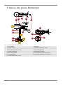
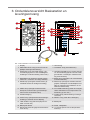
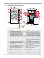
Illustration1: All parts of the multisensor
1 Rain gauge 2 Antenna
3 Circular level 4 Wind cups (wind speed)
5 wind vane (wind direction) 6 Thermo-Hygrometer
7 Pipe clamp 8 Mounting shoe
9 Mounting bar 10 Battery compartment (cover)
11 RESET button 12 LED function indicator
13 Mounting screws with nuts

7 / 56
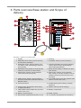
6 Parts overview Base station and Scope of
delivery
1
2
3
4
5
6
7
8
9
10
11
13
14
15
16
17
18
19
20
21
22
23
24
12
25
A
C
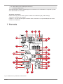
Illustration2: All parts of the base station
1 Display 2 Housing
3 SNOOZE/LIGHT button (snooze function
and temporary backlight)
4 CHANNEL button (channel selection)
5 GRAPH/UP button (Normal display.) His-
tory data in a bar chart/settings: value set-
ting upwards)
6 HISTORY/DOWN button (Normal display:
History data as single values/settings:
value setting downwards)
7 MAX/MIN button (display change between
maximum, minimum or current value)
8 BARO button (display of different air pres-
sure values)
9 WIND button (display change between
mean value and current gust)
10 RAIN button (display change between
daily, weekly or monthly rainfall as well as
rainfall in the last 24 hours and since the
last reset)
11 INDEX button (display change between
dew point, heat index, windchill index and
Beaufort index)
12 microUSB socket (insert the supplied USB
cable to connect with a PC*)
13 wall mount fixture 14 ALARM button (alarm setting or display
selection)
15 ALERT button (temperature alert setting
or display selection)
16 RESET button (reset all settings)
17 TIME SYNC button (initiate time synchron-
ization* with a PC)
18 Battery compartment
19 Battery compartment lid 20 Stand, fold-out
21 DATA button (initiate data transfer* to PC) 22 °C/°F button (temperature unit selection)

8 / 56
23 SENSOR button (search for wireless
sensor)
24 CLOCK SET button (setting time manu-
ally)
25 USB cable with microUSB (base station)
and USB-A plug (PC)
*For weather data transmission a PC with Windows 7 or higher and installed 'WEATHER TOOL' soft-
ware is required.
Delivery content:
Base unit (A), outdoor sensor (wireless multifunction sensor) (B), USB cable (C)
Also required (not included):
6 pcs. Mignon batteries (1.5V, type AA/LR06) for base station, 3 pcs. Mignon batteries (1.5V, type AA/
LR06) for wireless multifunction sensor

9 / 56
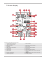
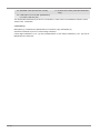
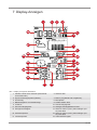
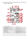
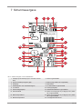
7 Screen display
1
4
3
28
2
6
7
9
11
10
13
12
14
15
17
16
19
20
22
21
24
18
23
26
25
27
5
8
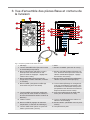
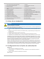
Illustration3: Screen display of the base station
1 Current time or alarm time
(hours:minutes:seconds)
2 Alarm enabled
3 Sync icon (time) 4 Date (day-month or reverse)
5 Weekday 6 Moon phase
7 Bar chart for value display 8 Air pressure alarm enabled
9 Air pressure 10 Sunrise time
11 Sunset time 12 Wind speed alarm enabled
13 Wind speed 14 Alarm for high (HI AL) or low (LO AL) value
enabled
15 Outdoor temperature 16 Alarm for high (HI AL) or low (LO AL) value
enabled
17 Indoor temperature 18 Humidity outdoors

10 / 56
19 Humidity indoors 20 Room climate Indicator
21 Sensor signal status 22 Sensor symbol
23 Wind/storm classification 24 Wind direction
25 Index (heat/dew point/UV/Beaufort) 26 Index value
27 Weather trend 28 AM/PM information in 12-hour time mode
8 Before starting operation
NOTICE
Avoid connectivity disruptions!
To avoid connectivity disruptions between the devices, consider the following points before starting
operation.
1. Place base station (receiver) and remote sensor (sender) together as close as possible.
2. Set up power supply for the base station and wait until the indoor temperature is displayed.
3. Set up power supply for the remote sensor.
4. Position the base station and the remote sensor within the effective transmission range.
5. Ensure that the base station and remote sensor are assigned to the same channel.
When changing batteries always change batteries in the main unit as well as all remote units and re-
place them in the correct order, so the remote connection can be re-established. If either of the
devices is mains-powered, the power supply must be disconnected for a short moment also for this
device when exchanging the batteries. If batteries are exchanged in only one of the devices (i.e. the
remote sensor) the signal can’t be received or can’t be received correctly.
Note, that the effective range is vastly affected by building materials and position of the main and re-
mote units. Due to external influences (various RC devices and other sources of interference), the
maximum distance can be greatly reduced. In such cases we suggest to position the main unit and the
remote sensor at other places. Sometimes all it takes is a relocation of one of these components of a
few inches!
9 Setting up power supply
Base unit
1. Remove the battery compartment cover.
2. Insert the batteries into the battery compartment. Ensure that the battery polarity (+/-) is correct.
3. Replace the battery compartment cover.
Remote sensor
4. Loosen the screw at the battery compartment cover with a small Philips screwdriver and remove
the cover.
5. Insert the batteries into the battery compartment. Ensure that the battery polarity (+/-) is correct.
6. Replace the cover and retighten it with the screw.

11 / 56
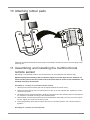
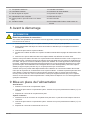
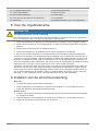
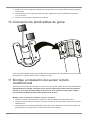
10 Attaching rubber pads
Attach the supplied self-adhesive rubber pads to the clamps as shown to ensure a firmer fitting of the
mounting rod.
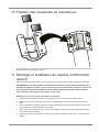
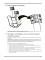
11 Assembling and installing the multifunctional
remote sensor
Depending on the desired location, the remote sensor can be installed in two different ways.
NOTICE!During the assembly make sure that the upper part of the wind vanve is minimum 1.5
meters off the ground. Use the circular level in the sensor head to ensure a level installation. The
windmill must point to the North.
Assembly on a vertical or horizontal wooden element
1. Slide one end of the assembly bar into the aperture below the sensor head.
2. Slide one screw through the bore hole and put on the nut on the opposite site. Tighten the screw
connection by hand.
3. Depending on the desired orientation, slide the opposite end of the assembly bar into the aperture
for vertical or horizontal mounting of the assembly base.
4. Slide another screw through the bore hole of the assembly base and put on the nut on the oppos-
ite site. Tighten the screw connection by hand.
5. Place the assembly base with its bottom site first on a wooden element. Use 4 wood screws to
tighten it.
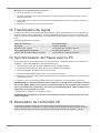
Assembly on a vertical or horizontal tube

12 / 56
6. Repeat steps 1 to 4 as before.
7. Place the assembly base with its bottom site first on the tube. Push the tube bracket against the
tube from the opposite site.
8. Slide 4 screws through the bore holes of the assemby base and through the bore holes of the tube
bracket on the other site.
9. Put on the 4 nuts and tighten the screw connection by hand.
12 Signal transmission
The base station will automatically connect to the multi outdoor sensor and (if available) to other wire-
less sensors. Press the SENSOR SYNC button to search for sensors directly. After successful con-
nection, the symbol for the outdoor area (OUT) and/or the channel are displayed.
Connection status display
Connection status Screen display
Good signal Reception icon
Searching for a sensor Reception symbol flashes
No signal for 48 hours 'Er' (Error) is shown
Sensor low battery status, good signal Battery symbol is shown
13 Time synchronization with the PC
Time and date are automatically synchronized for this unit when it is connected to a computer* using
the supplied USB cable. Proceed as follows:
1. Plug the microUSB plug of the USB cable into the USB socket on the device.
2. Plug the USB A plug of the USB cable into a free USB port on the computer.
3. Switch on the computer and wait about 5 seconds.
4. Start the 'WEATHER TOOL' software. This synchronizes the time.
5. Press the TIME SYNC button for about 8 seconds to deactivate or activate time synchronization.
6. Press the TIME SYNC button once to restart time synchronization.
NOTICE!The time synchronization is carried out via the software on the connected computer
with the time set there. Make sure that it is set correctly and that the software remains open un-
til the time has been synchronized. After successful synchronization, this is indicated by the syn-
chronization symbol in the display.
*Computer with Windows 7 or higher required.
NOTICE!If the device is connected to the computer via USB, it is supplied with power as soon as
the computer is switched on.
14 EC Declaration of Conformity
Hereby, Bresser GmbH declares that the equipment type with item number 7002571 : is in compli-
ance with Directive: 2014/30/EU. The full text of the EU declaration of conformity is available at the
following internet address: www.bresser.de/download/7002571/CE/7002571_CE.pdf
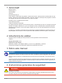
15 Disposal
Dispose of the packaging materials properly, according to their type, such as paper or card-
board. Contact your local waste-disposal service or environmental authority for information
on the proper disposal.

13 / 56
Do not dispose of electronic devices in the household garbage!
As per Directive 2012/19/EC of the European Parliament on waste electrical and electronic
equipment and its adaptation into German law, used electronic devices must be collected
separately and recycled in an environmentally friendly manner.
Do not dispose of batteries and rechargeable batteries with the household waste. You are leg-
ally required to return used batteries and rechargeable batteries. After they are used, the bat-
teries can be returned free of charge to our point of sale or to a nearby location (for example,
retailers or municipal collecting points).
Batteries and rechargeable batteries are marked with a symbol of a crossed-out dustbin and
the chemical symbol of the pollutant. “Cd” stands for Cadmium, “Hg” stands for mercury and
“Pb” stands for lead.

14 / 56
1 Impressum
Bresser GmbH
Gutenbergstr. 2
46414 Rhede
Germany
http://www.bresser.de
Für etwaige Gewährleistungsansprüche oder Serviceanfragen verweisen wir auf die Informationen zu
„Garantie“ und „Service“ in dieser Dokumentation. Wir bitten um Verständnis, dass direkt an die Her-
steller-Anschrift gerichtete Anfragen oder Einsendungen nicht bearbeitet werden können.
Irrtümer und technische Änderungen vorbehalten.
© 2019 Bresser GmbH
Alle Rechte vorbehalten.
Die Reproduktion dieser Dokumentation – auch auszugsweise – in irgendeiner Form (z.B. Fotokopie,
Druck, etc.) sowie die Verwendung und Verbreitung mittels elektronischer Systeme (z.B. Bilddatei,
Website, etc.) ohne eine vorherige schriftliche Genehmigung des Herstellers ist nicht gestattet.
Die in dieser Dokumentation verwendeten Bezeichnungen und Markennamen der jeweiligen Firmen
sind im Allgemeinen in Deutschland, der Europäischen Union und/oder weiteren Ländern waren-, mar-
ken- und/oder patentrechtlich geschützt.
2 Gültigkeitshinweis
Diese Dokumentation ist gültig für die Produkte mit den nachfolgend aufgeführten Artikelnummern:
7002571
Anleitungsversion: 1019
Bezeichnung dieser Anleitung:
Quickstart_7002571_PC-Weather-Station_en-de-fr-nl-es_BRESSER_v102019a
Informationen bei Serviceanfragen stets angeben.
3 Zu dieser Anleitung
HINWEIS
Diese Bedienungsanleitung ist als Teil des Gerätes zu betrachten!
Lesen Sie vor der Benutzung des Geräts aufmerksam die Sicherheitshinweise und die Bedienungsan-
leitung.
Bewahren Sie diese Bedienungsanleitung für die erneute Verwendung zu einem späteren Zeitpunkt
auf. Bei Verkauf oder Weitergabe des Gerätes ist die Bedienungsanleitung an jeden nachfolgenden
Besitzer/Benutzer des Produkts weiterzugeben.
4 Allgemeine Sicherheitshinweise
GEFAHR
Erstickungsgefahr!
Bei unsachgemäßer Verwendung dieses Produkts besteht Erstickungsgefahr, insbesondere für Kin-
der. Beachten Sie deshalb unbedingt die nachfolgenden Sicherheitsinformationen.

15 / 56
• Verpackungsmaterialien (Plastiktüten, Gummibänder, etc.) von Kindern fernhalten! Es besteht Er-
stickungsgefahr!
• Dieses Produkt beinhaltet Kleinteile, die von Kindern verschluckt werden können! Es besteht Ersti-
ckungsgefahr!
GEFAHR
Gefahr eines Stromschlags!
Dieses Gerät beinhaltet Elektronikteile, die über eine Stromquelle (Netzteil und/oder Batterien) betrie-
ben werden. Bei unsachgemäßer Verwendung dieses Produkts besteht die Gefahr eines Strom-
schlags. Ein Stromschlag kann zu schweren bis tödlichen Verletzungen führen. Beachten Sie daher
unbedingt die nachfolgenden Sicherheitsinformationen.
• Lassen Sie Kinder beim Umgang mit dem Gerät nie unbeaufsichtigt! Die Nutzung darf nur, wie in
der Anleitung beschrieben, erfolgen, andernfalls besteht die Gefahr eines Stromschlags!
GEFAHR
Explosionsgefahr!
Bei unsachgemäßer Verwendung dieses Produkts besteht Explosionsgefahr. Beachten Sie unbedingt
die nachfolgenden Sicherheitsinformationen, um eine Explosion zu vermeiden.
• Setzen Sie das Gerät keinen hohen Temperaturen aus. Benutzen Sie nur die empfohlenen Batteri-
en. Gerät und Batterien nicht kurzschließen oder ins Feuer werfen! Durch übermäßige Hitze und
unsachgemäße Handhabung können Kurzschlüsse, Brände und sogar Explosionen ausgelöst
werden!
HINWEIS
Gefahr von Sachschäden!
Bei unsachgemäßer Handhabung können das Gerät und/oder die Zubehörteile beschädigt werden.
Verwenden Sie das Gerät deshalb nur entsprechend den nachfolgenden Sicherheitsinformationen.
• Bauen Sie das Gerät nicht auseinander! Wenden Sie sich im Falle eines Defekts an Ihren Fach-
händler. Er nimmt mit dem Service-Center Kontakt auf und kann das Gerät ggf. zwecks Reparatur
einschicken.
• Gerät nicht in Wasser tauchen!
• Das Gerät keinen Stößen, Erschütterungen, Staub, dauerhaft hohen Temperaturen oder extremer
Feuchtigkeit aussetzen. Dies kann zu Fehlfunktionen, Kurzschlüssen sowie zu Beschädigungen
an Batterien und Bauteilen führen.
• Nur die empfohlenen Batterien verwenden. Schwache oder verbrauchte Batterien immer durch
komplett neuen Satz Batterien mit voller Kapazität ersetzen. Keine Batterien unterschiedlicher
Marken, Typen oder mit unterschiedlich hoher Kapazität verwenden. Batterien aus dem Gerät ent-
fernen wenn es längere Zeit nicht benutzt wird.
HINWEIS
Gefahr von Spannungsschäden!
Für Spannungsschäden in Folge falsch eingelegter Batterien übernimmt der Hersteller keine Haftung!

16 / 56
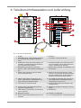
5 Teileübersicht Multisensor
1
3
4
5
6
9
8
7
13
10
11
E
D
F
G
7
8
12
2
Abb.1: Alle Teile des Multisensors
1 Regensammelbehälter 2 Antenne
3 Dosenlibelle 4 Windschalen (Windgeschwindigkeit)
5 Windfahne (Windrichtung) 6 Thermo-/Hygrometer
7 Rohrschelle 8 Montageschuh
9 Montagestange 10 Batteriefach(-abdeckung)
11 RESET-Knopf 12 LED-Funktionsleuchte
13 Montageschrauben mit -muttern

17 / 56
6 Teileübersicht Basisstation und Lieferumfang
1
2
3
4
5
6
7
8
9
10
11
13
14
15
16
17
18
19
20
21
22
23
24
12
25
A
C
Abb.2: Alle Teile der Basisstation
1 Display 2 Gehäuse
3 SNOOZE/LIGHT-Taste (Schlummerfunkti-
on und temporäre Hintergrundbeleuch-
tung)
4 CHANNEL-Taste (Kanalwahl)
5 GRAPH/UP-Taste (Normale Anzeige: His-
toriedaten im Balkendiagramm/Einstellun-
gen: Wertänderung aufwärts)
6 HISTORY/DOWN-Taste (Normale Anzei-
ge: Historiedaten als Einzelwerte/Einstel-
lungen: Wertänderung abwärts)
7 MAX/MIN-Taste (Wechsel zwischen
Höchst-, Tiefst- oder aktueller Werteanzei-
ge)
8 BARO-Taste (Anzeige verschiedener Luft-
druckwerte)
9 WIND-Taste (Wechsel zwischen Mittel-
wert und aktueller Böe)
10 RAIN-Taste (Wechsel zwischen Tages-,
Wochen- oder Monats-Niederschlagsmen-
ge sowie Niederschlag in den letzten 24
Stunden und seit dem letzten Reset)
11 INDEX-Taste (Wechsel zwischen Tau-
punkt-, Wärmeindex- und Kälteindex-An-
zeige sowie dem Beaufort-Index)
12 microUSB-Anschlussbuchse (Anschluss
des mitgelieferten USB-Kabels zwecks
Verbindung mit einem PC*)
13 Vorrichtung für Wandmontage 14 ALARM-Taste (Weckrufeinstellung oder
Anzeigenwahl)
15 ALERT-Taste (Temperaturalarmeinstel-
lung oder Anzeigenwahl)
16 RESET-Knopf (alle Einstellungen zurück-
setzen)
17 TIME SYNC-Knopf (Zeitsynchronisierung*
mit PC initiieren)
18 Batteriefach
19 Batteriefachdeckel 20 Standfuß, ausklappbar
21 DATA-Knopf (Datenübertragung* zum PC
initiieren)
22 °C/°F-Knopf (Wahl der Temperatureinheit)

18 / 56
23 SENSOR-Taste (Funksensor suchen) 24 CLOCK SET-Taste (manuelle Zeiteinstel-
lung)
25 USB-Kabel mit microUSB- (Basisstation)
und USB-A-Stecker (PC)
*Für Wetterdatenübermittlung ist ein PC mit Windows 7 oder höher und installierter Software ‚WEA-
THER TOOL‘ erforderlich.
Lieferumfang
Basisgerät (A), Außensensor (Multifunktions-Funksensor) (B), USB-Kabel (C)
Außerdem erforderlich (nicht im Lieferumfang enthalten):
6 Stck. Mignon-Batterien (1.5V, Typ AA) für Basisstation, 3 Stck. Mignon-Batterien (1.5V, Typ AA) für
Multifunktions-Funksensor

19 / 56
7 Display-Anzeigen
1
4
3
28
2
6
7
9
11
10
13
12
14
15
17
16
19
20
22
21
24
18
23
26
25
27
5
8
Abb.3: Display-Anzeige der Basisstation
1 Aktuelle Uhrzeit oder Weckzeit (Stunden:Mi-
nuten:Sekunden)
2 Weckruf aktiv
3 Synchronisierungssymbol (Uhrzeit) 4 Datum (Tag-Monat oder umgekehrt)
5 Wochentag 6 Mondphase
7 Balkendiagramm zur Werteanzeige 8 Luftdruckalarm aktiv
9 Luftdruck 10 Sonnenaufgangszeit
11 Sonnenuntergangszeit 12 Windgeschwindigkeitsalarm aktiv
13 Windgeschwindigkeit 14 Alarm für hohen (HI AL) oder niedrigen (LO
AL) Wert aktiv
15 Außentemperatur 16 Alarm für hohen (HI AL) oder niedrigen (LO
AL) Wert aktiv
17 Innentemperatur 18 Außenluftfeuchtigkeit

20 / 56
19 Innenluftfeuchtigkeit 20 Raumklimaindikator
21 Sensor-Signalstatus 22 Sensorsymbol
23 Wind-/Sturmeinstufung 24 Windrichtung
25 Index (Hitze/Taupunkt/UV/Beaufort) 26 Indexwert
27 Wettertrend 28 AM/PM-Information im 12-Stunden-Zeitmodus
8 Vor der Inbetriebnahme
HINWEIS
Vermeidung von Verbindungsstörungen!
Um Verbindungsstörungen zwischen den Geräten zu vermeiden, sind die folgenden Punkte bei der In-
betriebnahme zu beachten.
1. Basisgerät (Empfänger) und Sensor (Sender) so nah wie möglich nebeneinander stellen/legen.
2. Stromversorgung für das Basisgerät herstellen und warten bis die Innentemperatur angezeigt wird.
3. Stromversorgung für den Sensor herstellen.
4. Basisgerät und Sensor innerhalb des effektiven Übertragungsbereichs aufstellen/betreiben.
5. Sicherstellen, dass Basisgerät und Funksensor auf den gleichen Kanal eingestellt sind.
Bei einem Batteriewechsel stets die Batterien sowohl im Basisgerät als auch im Sensor entfernen und
in richtiger Reihenfolge wieder neu einsetzen, damit die Funkverbindung erneut aufgebaut werden
kann. Wird eines der beiden Geräte über einen Netzstromanschluss betrieben, so muss auch für die-
ses bei einem Batteriewechsel kurzzeitig die Stromverbindung getrennt werden. Werden z.B. nur die
Batterien im Sensor ausgetauscht, kann das Signal anschließend gar nicht oder nicht mehr korrekt
empfangen werden.
Beachten Sie, dass die tatsächliche Reichweite von den jeweils verwendeten Baumaterialien der Ge-
bäude sowie der jeweiligen Position der Basiseinheit und des Außensensors abhängt. Durch externe
Einflüsse (diverse Funksender und andere Störquellen) kann sich die mögliche Reichweite stark ver-
ringern. In solchen Fällen empfehlen wir, sowohl für das Basisgerät als auch den Außensensor andere
Standorte zu suchen. Manchmal reicht schon ein Verschieben um wenige Zentimeter!
9 Stromversorgung herstellen
Basisgerät
1. Batteriefachdeckel entfernen.
2. Batterien in das Batteriefach einsetzen. Dabei die korrekte Ausrichtung der Batteriepole (+/-) be-
achten.
3. Batteriefachdeckel wieder aufsetzen.
Funksensor
4. Schraube am Batteriefachdeckel mit einem geeigneten Kreuzschraubendreher entfernen und Bat-
teriefachdeckel abnehmen.
5. Batterien in das Batteriefach einsetzen. Dabei die korrekte Ausrichtung der Batteriepole (+/-) be-
achten.
6. Batteriefachdeckel wieder aufsetzen und anschrauben.
Seite laden ...
Seite laden ...
Seite laden ...
Seite laden ...
Seite laden ...
Seite laden ...
Seite laden ...
Seite laden ...
Seite laden ...
Seite laden ...
Seite laden ...
Seite laden ...
Seite laden ...
Seite laden ...
Seite laden ...
Seite laden ...
Seite laden ...
Seite laden ...
Seite laden ...
Seite laden ...
Seite laden ...
Seite laden ...
Seite laden ...
Seite laden ...
Seite laden ...
Seite laden ...
Seite laden ...
Seite laden ...
Seite laden ...
Seite laden ...
Seite laden ...
Seite laden ...
Seite laden ...
Seite laden ...
Seite laden ...
Seite laden ...
-
 1
1
-
 2
2
-
 3
3
-
 4
4
-
 5
5
-
 6
6
-
 7
7
-
 8
8
-
 9
9
-
 10
10
-
 11
11
-
 12
12
-
 13
13
-
 14
14
-
 15
15
-
 16
16
-
 17
17
-
 18
18
-
 19
19
-
 20
20
-
 21
21
-
 22
22
-
 23
23
-
 24
24
-
 25
25
-
 26
26
-
 27
27
-
 28
28
-
 29
29
-
 30
30
-
 31
31
-
 32
32
-
 33
33
-
 34
34
-
 35
35
-
 36
36
-
 37
37
-
 38
38
-
 39
39
-
 40
40
-
 41
41
-
 42
42
-
 43
43
-
 44
44
-
 45
45
-
 46
46
-
 47
47
-
 48
48
-
 49
49
-
 50
50
-
 51
51
-
 52
52
-
 53
53
-
 54
54
-
 55
55
-
 56
56


Bresser 7902571 Bedienungsanleitung
- Typ
- Bedienungsanleitung
- Dieses Handbuch ist auch geeignet für
in anderen Sprachen
- français: Bresser 7902571 Le manuel du propriétaire
- español: Bresser 7902571 El manual del propietario
- Nederlands: Bresser 7902571 de handleiding
Verwandte Papiere
-
Bresser PC Bedienungsanleitung
-
-
-
-
Bresser 7902580 Bedienungsanleitung
-
-
-
Bresser 7002586 Bedienungsanleitung
-
-
Bresser 9080500 - Colour Weather Center 5-in-1 National Geographic Bedienungsanleitung
