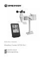
Bresser Weather Center WTW 5in1 Bedienungsanleitung
- Kategorie
- Wetterstationen
- Typ
- Bedienungsanleitung
Dieses Handbuch eignet sich auch für

Weather Station · Wetterstation ·
Weather Center WTW 5in1
EN Instruction manual
DE Bedienungsanleitung

DE
Besuchen Sie unsere Website über den folgenden QR Code oder Weblink um weitere Informationen
zu diesem Produkt oder die verfügbaren Übersetzungen dieser Anleitung zu finden.
EN
Visit our website via the following QR Code or web link to find further information on this product or
the available translations of these instructions.
FR
Si vous souhaitez obtenir plus d’informations concernant ce produit ou rechercher ce mode
d’emploi en d’autres langues, rendez-vous sur notre site Internet en utilisant le code QR ou le lien
correspondant.
NL
Bezoek onze internetpagina via de volgende QR-code of weblink, voor meer informatie over dit
product of de beschikbare vertalingen van deze gebruiksaanwijzing.
ES
¿Desearía recibir unas instrucciones de uso completas sobre este producto en un idioma determinado?
Entonces visite nuestra página web utilizando el siguiente enlace (código QR) para ver las versioneAs
disponibles.
IT
Desidera ricevere informazioni esaustive su questo prodotto in una lingua specifica? Venga a
visitare il nostro sito Web al seguente link (codice QR Code) per conoscere le versioni disponibili.
www.bresser.de/P7002585
www.bresser.de/warranty_terms
GARANTIE · WARRANTY · GARANTÍA · GARANZIA
APP DOWNLOAD: APP DOWNLOAD:
Weather Underground is a registered trademark of The Weather Channel, LLC. both in the United States and internationally. The Weather
Underground Logo is a trademark of Weather Underground, LLC. Find out more about Weather Underground at www.wunderground.com
Apple and the Apple logo are trademarks of Apple Inc., registered in the U.S. and other countries. App Store is a service mark of Apple Inc.,
registered in the U.S. and other countries. Google Play and the Google Play logo are trademarks of Google Inc.

English...................................................................................................................
4
Deutsch .................................................................................................................
15

4 / 28
1 Imprint
Bresser GmbH
Gutenbergstr. 2
46414 Rhede
Germany
http://www.bresser.de
If you wish to submit a warranty claim or service request, please refer to the “Warranty” and “Service”
information in this document. Please be aware that any requests or submissions sent directly to the
manufacturer cannot be processed.
Errors excepted. Subject to technical modifications.
© 2019 Bresser GmbH
All rights reserved.
Reproduction of this document, including extracts, in any form (photocopied, printed etc.) or the use
and distribution of this document by electronic means (image file, website etc.) is not permitted without
the prior written consent of the manufacturer.
The terms and brand names of the respective companies used in this document are protected by
brand, patent or product law in Germany, the European Union and/or other countries.
2 Validity information
This documentation is valid for the products with the article numbers listed below:
7002585
Manual version: v0619
Manual description:
Manual_7002585_Weather-Center-WTW-5in1_en-de_BRESSER_v062019a
With any service inquiries, please state these information.
3 Features
• Measurement of Rainfall
• Measurement of wind speed
• Measurement of wind direction
• Internet time synchronization via PC
• Alarm with snooze function
• Outdoor temperature alarm (frost warning)
• Outdoor temperature (in °C or °F)
• Indoor temperature (in °C or °F)
• Humidity indoor/outdoor
• Barometric pressure
• Since function to display the total rainfall from a customized point in time.
• Highest and lowest value display
• Maximum/Minimum value memory
• Colour display
• Backlight

5 / 28
4 About this Instruction Manual
NOTICE
These operating instructions are to be considered a component of the device.
Please read the safety instructions and the operating instructions carefully before use.
Keep these instructions for renewed use at a later date. When the device is sold or given to someone
else, the instruction manual must be provided to the new owner/user of the product.
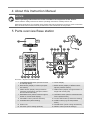
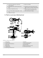
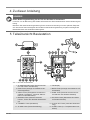
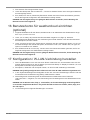
5 Parts overview Base station
1
2
8
16
1510
18
13
12 1411
25
A
B
C
3
4
6
5
7
17
19
22
20
9
24
23
18
21
Illustration1: All parts of the base station
1 ALARM/SNOOZE button (snooze function
or interrupt alarm)
2 Colour display
3 RAIN button (display of various precipita-
tion values)
4 BARO button (display of different atmo-
spheric pressure values)
5 INDEX button (display change between
'feels like' temperature, dew point, heat in-
dex and wind chill index)
6 WIND button (display change between av-
erage and current gust)
7 MAX/MIN button (switch between highest,
lowest or current value display)
8 HISTORY button (retrieve measurements
for the past 24 hours)
9 CHANNEL button (channel selection) 10 CLOCK SET button (manual time setting)
11 ALARM button (Alarm setting) 12 ALERT button (e.g. set temperature
alarm)
13 Wall mount 14 DOWN button (value setting downwards)
15 UP button (value setting upwards) 16 RESET button (reset all settings)

6 / 28
17 HI/LO/AUTO slider (turn on/off back-
ground lighting)
18 Stand, removable
19 REFRESH button (refreshing data manu-
ally)
20 SENSOR / WI-FI button (start manual
sensor search or activate / deactivate WI-
FI)
21 Battery compartment (cover) 22 BARO UNIT button (change of atmo-
spheric pressure measurement unit)
23 °C/°F slider (display change betw. °C and
°F)
24 USB socket (power supply)
25 USB power adapter
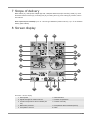
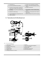
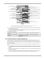
6 Parts overview Multisensor
1
3
4
5
6
9
8
7
13
10
11
E
D
F
G
7
8
12
2
Illustration2: All parts of the multisensor
1 Rain gauge 2 Antenna
3 Circular level 4 Wind cups (wind speed)
5 wind vane (wind direction) 6 Thermo-Hygrometer
7 Pipe clamp 8 Mounting shoe
9 Mounting bar 10 Battery compartment (cover)
11 RESET button 12 LED function indicator
13 Mounting screws with nuts

7 / 28
7 Scope of delivery
Base station (A), USB power adapter (B) with 2 adapter attachments (EU and UK), stand (C), multi-
functional outdoor sensor (D), mounting rod (E), mounting shoe (F), tube clamp (G), screws, instruc-
tion manual
Also required (not included):3 pcs. of 1.5V AA type batteries (outdoor sensor), 1 pc. of 3V CR2032
battery (base station)
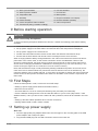
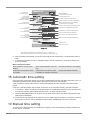
8 Screen display
23
2
1
9
10
15
14
18
7
4
21
20
8
22
3
5
6
13
11
12
17
16
19
Illustration3: Screen display
1 Wind speed 2 Wind direction
3 Signal strength for outdoor sensor 4 Outdoor temperature
5 Outdoor temperature alarm enabled (HI/
LO)
6 Outdoor humidity
7 Barometric pressure 8 Precipitation alarm enabled (HI/LO)
9 Precipitation amount 10 Date

8 / 28
11 WIFI synchronization 12 Ice alert enabled
13 Wake-up alarm enabled 14 Current time
15 Temperature felt 16 Moon phase
17 Weekday 18 Graphical weather trend display
19 Indoor humidity 20 Comfort indicator (climate)
21 Indoor temperature alarm enabled 22 Indoor temperature
23 Trend arrow (rising, constant or falling)
9 Before starting operation
NOTICE
Avoid connectivity disruptions!
To avoid connectivity disruptions between the devices, consider the following points before starting
operation.
1. Place base station (receiver) and remote sensor (sender) together as close as possible.
2. Set up power supply for the base station and wait until the indoor temperature is displayed.
3. Set up power supply for the remote sensor.
4. Position the base station and the remote sensor within the effective transmission range.
5. Ensure that the base station and remote sensor are assigned to the same channel.
When changing batteries always change batteries in the main unit as well as all remote units and re-
place them in the correct order, so the remote connection can be re-established. If either of the
devices is mains-powered, the power supply must be disconnected for a short moment also for this
device when exchanging the batteries. If batteries are exchanged in only one of the devices (i.e. the
remote sensor) the signal can’t be received or can’t be received correctly.
Note, that the effective range is vastly affected by building materials and position of the main and re-
mote units. Due to external influences (various RC devices and other sources of interference), the
maximum distance can be greatly reduced. In such cases we suggest to position the main unit and the
remote sensor at other places. Sometimes all it takes is a relocation of one of these components of a
few inches!
10 First Steps
Follow the bullet points in order, to ensure a successful setup.
• Setting up power supply (base station and wireless sensor)
• Mount the remote sensor
• The base station is now in AP mode (LED flashes green) and ready for initial setup.
• Create a Weather Underground account and add the station to your account ("My Profile" / "Add
Weather station"). Here you will receive a station ID and a password, which will be needed in the next
step.
• Setting up the base station (Estabish Wi-Fi / Router connection)
• Viewing weather data via web, mobile or tablet
11 Setting up power supply
Base unit
1. Push the appropriate plug adapter attachment onto the spigot on the mounting plate of the USB
power adapter until it snaps into place.
2. Plug the MicroUSB plug into the USB connection socket on the base unit.

9 / 28
3. Insert the mains plug into the power outlet.
4. The device is energized directly.
Installing the backup battery:
1. Remove the battery compatment cover.
2. Insert the battery into the battery compartment. Make sure that the battery polarity (+/-) is correct .
3. Replace the battery compartment cover.
Remote sensor
5. Loosen the screw at the battery compartment cover with a small Philips screwdriver and remove
the cover.
6. Insert the batteries into the battery compartment. Ensure that the battery polarity (+/-) is correct.
7. Replace the cover and retighten it with the screw.
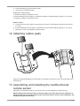
12 Attaching rubber pads
Attach the supplied self-adhesive rubber pads to the clamps as shown to ensure a firmer fitting of the
mounting rod.
13 Assembling and installing the multifunctional
remote sensor
Depending on the desired location, the remote sensor can be installed in two different ways.
NOTICE!During the assembly make sure that the upper part of the wind vanve is minimum 1.5
meters off the ground. Use the circular level in the sensor head to ensure a level installation. The
windmill must point to the North.

10 / 28
Assembly on a vertical or horizontal wooden element
1. Slide one end of the assembly bar into the aperture below the sensor head.
2. Slide one screw through the bore hole and put on the nut on the opposite site. Tighten the screw
connection by hand.
3. Depending on the desired orientation, slide the opposite end of the assembly bar into the aperture
for vertical or horizontal mounting of the assembly base.
4. Slide another screw through the bore hole of the assembly base and put on the nut on the oppos-
ite site. Tighten the screw connection by hand.
5. Place the assembly base with its bottom site first on a wooden element. Use 4 wood screws to
tighten it.
Assembly on a vertical or horizontal tube
6. Repeat steps 1 to 4 as before.
7. Place the assembly base with its bottom site first on the tube. Push the tube bracket against the
tube from the opposite site.
8. Slide 4 screws through the bore holes of the assemby base and through the bore holes of the tube
bracket on the other site.
9. Put on the 4 nuts and tighten the screw connection by hand.
14 Signal transmission
The base station will automatically connect to the multi outdoor sensor and (if available) to other wire-
less sensors.You can also press the Wi-Fi / SENSOR button to start a manual search for the remote
sensors. When the connection is successful, the outdoor symbol (OUT) and/or the channel will be
shown on the display.
Connection status display
Connection status Screen display
Good signal Reception symbol
Sensor searching mode Reception symbolcon flashes
No signal over 48 hours 'Er' (Error) is shown
Sensors low battery with good signal Battery symbol is shown
15 Setting up an user account for Weather
Underground (optional)
1. Enter the following web address in the address bar of the web browser for the 'Weather Under-
ground' service: https://www.wunderground.com
2. Click on 'Join' to open registration page.
3. Type in the personal user data and click on ‚Sign up‘.
4. Follow the further setup steps.
5. You can add your own weather station under the menu point 'Sensor Network'> 'Connect a
Weather Station'.
6. A 'Station ID' and a 'Station Key/Password' will be generated automatically by the service. They
are needed for later configuration of the weather station.
NOTICE!Use a valid e-mail address for registration. Otherwise the service can not be used.

11 / 28
16 Setting up an user account for weathercloud
(optional)
1. Enter the following web address for the 'weathercloud' service in the address bar of the web
browser: https://weathercloud.net
2. Type in the personal user data and click on ‚Sign up‘.
3. After registration and verification of the e-mail address chose the menue point 'Devices' in the user
account.
4. Click on the link 'Create device' under 'Your devices' and follow the instructions to add a new
device. For 'Model' chose the option 'W100 Series' under 'CCL. For 'Link type' chose the option
'Pro Weather Link'.
5. A 'weathercloud ID' and a 'Key' will be generated automatically by the service. They are needed
for later configuration of the weather station.
NOTICE!Use a valid e-mail address for registration. Otherwise the service can not be used.
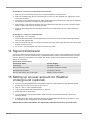
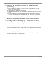
17 Configuration / Setting up a WI-FI connection
1. If the base station has not yet been connected to a router, it will switch to AP (Access Point Mode)
mode after the first power supply. The display will show 'AP' and the symbol for WI-FI synchroniza-
tion.
2. Use a smartphone, tablet or computer to connect to Wi-Fi.
NOTICE!The respective device itself must also be equipped with a WI-FI function.
3. In the system settings of the device, switch to W-LAN or WI-FI settings and select the wireless net-
work (SSID) named 'PWS-XXXXXX'.
4. After successful connection via the address bar of the web browser, enter the IP address
'http: //192.168.1.1' to establish a connection to the settings menu of the weather station.
NOTICE!Always prepend 'http: //' to the IP address to avoid browser dependent connection er-
rors. Recommended browsers: the latest version of Chrome, Safari, Edge, Firefox or Opera.
5. Make the following settings in the settings menu:

12 / 28
Select 'Add Router'
to add a router manually**
Select 'ADVANCED'
to enter advanced settings menu
Select desired WI-FI router
If router is not listed, enter SSID manually
Select security type of the router (normally WAP2)
Enter password of the Router (leave field blank
if no password has been assigned)
Check to comfirm upload to Weather underground*
Enter 'Station ID' registered at Wunderground*
Enter 'Station Key' registered at Wunderground*
Check to comfirm upload to Weathercloud*
Enter 'Station ID' registered at Weathercloud*
Enter 'Station Key' registered at Weathercloud*
Select time server
Click to confirm entries
Select 'SETUP'
to enter settings menu
Select 'Search'
to search for a router
*Leave field blank if registration is not yet available and entries are to be made later.
**Manual setup requires additional router information (including e.g. IP address, SSID, etc)
Password record
(if a password was entered)
ID record
(if an ID was entered)
Key record
(if a key was entered)
ID record
(if an ID was entered)
Key record
(if a key was entered)
6. After completing the settings, the device will recognize the default WI-FI connection after each re-
start.
7. In Access Point Mode, the WI-FI / SENSOR button can be pressed for 6 seconds to restore the
previous settings.
WI-FI connection status:
WI-FI symbol is shown in the
display
WI-FI symbol flashes in the dis-
play
AP symbol flashes in the display
Connection to the WI-FI router
successful
Connection to the WI-FI router
not stable or ongoing connection
Access Point Mode enabled
18 Automatic time setting
Once the power supply and internet connection is established, the time and date information (UTC Co-
ordinated Universal Time) is transmitted by the internet time server automatically.
If the reception is correct, date and time are set automatically and the reception icon 'SYNC' is dis-
played.
If the time / date information has not been received or is not received correctly, proceed as follows:
1. In countries / regions whose time zone differs from the coordinated world time UTC, the time zone
must be set manually (see chapter 'Set time zone ') to show the correct time.
2. Press the REFRESH button on the base unit for about 2 seconds to re-initiate retrievement of the
Internet time information.
3. Check the W-LAN settings on the base unit for correctness and, if necessary, correct them so that
an Internet connection can be established (see chapter, Establishing a W-LAN connection).
19 Manual time setting
To set the time / date manually, first disable the reception of the time signal by pressing the RCC but-
ton for approx. 8 seconds.

13 / 28
1. Press and hold CLOCK SET button for approx. 3 seconds to change to time setting mode.
2. Digits to be set are flashing.
3. Press UP or DOWN button to change the value.
4. Press CLOCK SET button to confirm and continue to the next setting.
5. Settings order: time offset > daylight saving time on/off > hours > minutes > 12/24 hours mode >
year > month > day > day/month display change > time synchronization on/off > language
NOTICE!When time is set manually, the time synchronization must be deactivated.
6. Finally press the CLOCK SET button to save the settings and exit the setting mode.
NOTICE!In normal display mode, press CLOCK SET button to switch between year display and
date display. In setting mode, press CLOCK SET button for about 2 seconds to return to the nor-
mal display mode.
20 Time zone setting
To set a different time zone, proceed as follows:
1. Press and hold CLOCK SET button for approx. 3 seconds to change to time setting mode. The
current value fore the time offset flashes.
2. Press up or DOWN button to set the desired hour value (0 to 10 hours) for the time offset.
3. Finally press the CLOCK SET button for approx. 3 seconds to save the settings and exit the set-
ting mode.
21 Manual measurement display
1. Press MAX/MIN button several times to display the stored values one after another.
2. Display order: Current values > MAX (highest values) > MIN (lowest values)
3. When highest or lowest values are dsiplayed, press and hold MAX/MIN button for approx. 3
seconds to switch temperature unit display from °C to °F or reverse.
NOTICE!Saved highest and lowest values will be deleted automatically every day on 0:00!
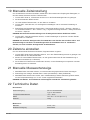
22 Technical data
Base station
Power supply DC 5V 1A mains adapter
Type: YLJXC-050100
Temperature measuring range -5°C – 50°C
Dimensions 79 x 157 x 41 mm (W x H x D)
Weight 130 g
Multisensor
Batteries 3x AA, 1.5V
Emergency power supply Solar panel
Maximum number of sensors 1x wireless multisensor
1x wireless indoor sensor (optional)
RF Transmission frequency 868Mhz
RF Transmission range 150 m
Maximum transmission power < 25mW
Temperature measuring range -40°C – 60°C (-40°F – 140°F)

14 / 28
Barometer measuring range 540 – 1100hPa (Relative Reichweite: 930 –
1050hPa)
Humidity measuring range 1 – 99%
Humidity resolution 1% HR
Precipitation measuring range 0 – 19999 mm (0 – 787.3 inch)
Wind speed measuring range 0 – 112 mph, 50 m/s, 180km/h, 97 knots
UV Index Range 1 – 16
Dimensions 392.2 x 326 x 144.5 mm (B x H x T)
Weight 1096g
Wi-Fi Specifications
Wi-Fi Standard 802.11 b/g/n
Wi-Fi Operating frequency 2.4 GHz
Supported devices Smart devices with built-in Wi-Fi AP mode (Ac-
cess Point) function, PCs or laptops, Android or
iOS Smartphones/Tablets
Supported Internet browsers Internet browsers that support HTML 5
23 EC Declaration of Conformity
Hereby, Bresser GmbH declares that the equipment type with item number 7002585 : is in compli-
ance with Directive: 2014/30/EU. The full text of the EU declaration of conformity is available at the
following internet address: www.bresser.de/download/7002585/CE/7002585_CE.pdf
24 Disposal
Dispose of the packaging materials properly, according to their type, such as paper or card-
board. Contact your local waste-disposal service or environmental authority for information
on the proper disposal.
Do not dispose of electronic devices in the household garbage!
As per Directive 2012/19/EC of the European Parliament on waste electrical and electronic
equipment and its adaptation into German law, used electronic devices must be collected
separately and recycled in an environmentally friendly manner.
Do not dispose of batteries and rechargeable batteries with the household waste. You are leg-
ally required to return used batteries and rechargeable batteries. After they are used, the bat-
teries can be returned free of charge to our point of sale or to a nearby location (for example,
retailers or municipal collecting points).
Batteries and rechargeable batteries are marked with a symbol of a crossed-out dustbin and
the chemical symbol of the pollutant. “Cd” stands for Cadmium, “Hg” stands for mercury and
“Pb” stands for lead.

15 / 28
1 Impressum
Bresser GmbH
Gutenbergstr. 2
46414 Rhede
Germany
http://www.bresser.de
Für etwaige Gewährleistungsansprüche oder Serviceanfragen verweisen wir auf die Informationen zu
„Garantie“ und „Service“ in dieser Dokumentation. Wir bitten um Verständnis, dass direkt an die Her-
steller-Anschrift gerichtete Anfragen oder Einsendungen nicht bearbeitet werden können.
Irrtümer und technische Änderungen vorbehalten.
© 2019 Bresser GmbH
Alle Rechte vorbehalten.
Die Reproduktion dieser Dokumentation – auch auszugsweise – in irgendeiner Form (z.B. Fotokopie,
Druck, etc.) sowie die Verwendung und Verbreitung mittels elektronischer Systeme (z.B. Bilddatei,
Website, etc.) ohne eine vorherige schriftliche Genehmigung des Herstellers ist nicht gestattet.
Die in dieser Dokumentation verwendeten Bezeichnungen und Markennamen der jeweiligen Firmen
sind im Allgemeinen in Deutschland, der Europäischen Union und/oder weiteren Ländern waren-, mar-
ken- und/oder patentrechtlich geschützt.
2 Gültigkeitshinweis
Diese Dokumentation ist gültig für die Produkte mit den nachfolgend aufgeführten Artikelnummern:
7002585
Anleitungsversion: v0619
Bezeichnung dieser Anleitung:
Manual_7002585_Weather-Center-WTW-5in1_en-de_BRESSER_v062019a
Informationen bei Serviceanfragen stets angeben.
3 Eigenschaften
• Messung der Niederschlagsmenge
• Messung der Windgeschwindigkeit
• Messung der Windrichtung
• Internetzeit-Synchronisation per PC
• Weckruf mit Schlummerfunktion (Snooze)
• Außentemperaturalarm (Frostwarnung)
• Außentemperatur (in °C oder °F)
• Innentemperatur (in °C oder °F)
• Luftfeuchtigkeit innen/außen
• Luftdruck
• Since-Funktion zur Anzeige des gesamten Niederschlags ab einem bestimmten Zeitpunkt??
• Tiefst- und Höchstwertanzeige
• Max-/Min-Werte Speicherung
• Farbdisplay
• Hintergrundbeleuchtung

16 / 28
4 Zu dieser Anleitung
HINWEIS
Diese Bedienungsanleitung ist als Teil des Gerätes zu betrachten!
Lesen Sie vor der Benutzung des Geräts aufmerksam die Sicherheitshinweise und die Bedienungsan-
leitung.
Bewahren Sie diese Bedienungsanleitung für die erneute Verwendung zu einem späteren Zeitpunkt
auf. Bei Verkauf oder Weitergabe des Gerätes ist die Bedienungsanleitung an jeden nachfolgenden
Besitzer/Benutzer des Produkts weiterzugeben.
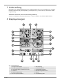
5 Teileübersicht Basisstation
1
2
8
16
1510
18
13
12 1411
25
A
B
C
3
4
6
5
7
17
19
22
20
9
24
23
18
21
Abb.1: Alle Teile der Basisstation
1 ALARM/SNOOZE-Taste (Schlummerfunk-
tion oder Alarm unterbrechen)
2 Farbdisplay
3 RAIN-Taste (Anzeige verschiedener Nie-
derschlagswerte)
4 BARO-Taste (Anzeige verschiedener Luft-
druckwerte)
5 INDEX-Taste (Anzeigewechsel zwischen
gefühlter Temperatur, Taupunkt, Wärme-
index und Windkühlfaktor)
6 WIND-Taste (Wechsel zwischen durch-
schnittlicher und aktueller Windböe)
7 MAX/MIN-Taste (Wechsel zwischen
Höchst-, Tiefst- oder aktueller Werteanzei-
ge)
8 HISTORY-Taste (Messwerte der letzten
24 Stunden abrufen)
9 CHANNEL-Taste (Kanalwahl) 10 CLOCK SET-Taste (manuelle Zeiteinstel-
lung)
11 ALARM-Taste (Weckrufeinstellung) 12 ALERT-Taste (u.a. Temperaturalarm ein-
stellen)

17 / 28
13 Wandhalterung 14 DOWN-Taste (Wertänderung abwärts)
15 UP-Taste (Wertänderung aufwärts) 16 RESET-Taste (alle Einstellungen zurück-
setzen)
17 HI/LO/AUTO-Schieberegler (Hintergrund-
beleuchtung einstellen oder ausschalten)
18 Standfuß, abnehmbar
19 REFRESH-Taste (manuelle Aktualisierung
der Daten)
20 SENSOR/WI-FI-Taste (manuelle Sensor-
suche starten oder WI-FI aktivieren/deakti-
vieren)
21 Batteriefach(-abdeckung) 22 BARO UNIT-Taste (Wechel der Luftdruck-
Maßeinheit)
23 °C/°F-Schieberegler (Anzeigewechsel zwi-
schen °C und °F)
24 USB-Anschlussbuchse (Stromversorgung)
25 USB-Netzadapter
6 Teileübersicht Multisensor
1
3
4
5
6
9
8
7
13
10
11
E
D
F
G
7
8
12
2
Abb.2: Alle Teile des Multisensors
1 Regensammelbehälter 2 Antenne
3 Dosenlibelle 4 Windschalen (Windgeschwindigkeit)
5 Windfahne (Windrichtung) 6 Thermo-/Hygrometer
7 Rohrschelle 8 Montageschuh
9 Montagestange 10 Batteriefach(-abdeckung)
11 RESET-Knopf 12 LED-Funktionsleuchte
13 Montageschrauben mit -muttern

18 / 28
7 Lieferumfang
Basisstation (A), USB-Netzadapter (B) mit 2 Adapteraufsätzen (EU und UK), Standfuß (C), multifunk-
tionaler Außensensor (D), Montagestab (E), Montageschuh (F), Rohrschelle (G), Schrauben, Bedie-
nungsanleitung
Außerdem erforderlich (nicht im Lieferumfang enthalten):
3 Stück 1.5V Batterien Typ AA (Außensensor), 1 Stück 3V Batterie Typ CR2032 (Basisstation)
8 Displayanzeigen
23
2
1
9
10
15
14
18
7
4
21
20
8
22
3
5
6
13
11
12
17
16
19
Abb.3: Displayanzeigen
1 Windgeschwindigkeit 2 Windrichtung
3 Empfangssignalstärke Außensensor 4 Außentemperatur
5 Temperaturalarm Außenbereich aktiv 6 Außenluftfeuchtigkeit
7 Luftdruck 8 Niederschlagsalarm aktiv
9 Niederschlagsmenge 10 Datum
11 W-LAN Synchronisation 12 Frostwarnung aktiv

19 / 28
13 Weckruf aktiv 14 Aktuelle Uhrzeit
15 Gefühlte Temperatur 16 Mondphase
17 Wochentag 18 Grafische Wettertrend-Anzeige
19 Innenluftfeuchtigkeit 20 Komfortindikator (Klima)
21 Temperaturalarm Innenbereich aktiv 22 Innentemperatur
23 Trendpfeil (steigend, gleichbleibend oder
fallend)
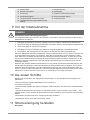
9 Vor der Inbetriebnahme
HINWEIS
Vermeidung von Verbindungsstörungen!
Um Verbindungsstörungen zwischen den Geräten zu vermeiden, sind die folgenden Punkte bei der In-
betriebnahme zu beachten.
1. Basisgerät (Empfänger) und Sensor (Sender) so nah wie möglich nebeneinander stellen/legen.
2. Stromversorgung für das Basisgerät herstellen und warten bis die Innentemperatur angezeigt wird.
3. Stromversorgung für den Sensor herstellen.
4. Basisgerät und Sensor innerhalb des effektiven Übertragungsbereichs aufstellen/betreiben.
5. Sicherstellen, dass Basisgerät und Funksensor auf den gleichen Kanal eingestellt sind.
Bei einem Batteriewechsel stets die Batterien sowohl im Basisgerät als auch im Sensor entfernen und
in richtiger Reihenfolge wieder neu einsetzen, damit die Funkverbindung erneut aufgebaut werden
kann. Wird eines der beiden Geräte über einen Netzstromanschluss betrieben, so muss auch für die-
ses bei einem Batteriewechsel kurzzeitig die Stromverbindung getrennt werden. Werden z.B. nur die
Batterien im Sensor ausgetauscht, kann das Signal anschließend gar nicht oder nicht mehr korrekt
empfangen werden.
Beachten Sie, dass die tatsächliche Reichweite von den jeweils verwendeten Baumaterialien der Ge-
bäude sowie der jeweiligen Position der Basiseinheit und des Außensensors abhängt. Durch externe
Einflüsse (diverse Funksender und andere Störquellen) kann sich die mögliche Reichweite stark ver-
ringern. In solchen Fällen empfehlen wir, sowohl für das Basisgerät als auch den Außensensor andere
Standorte zu suchen. Manchmal reicht schon ein Verschieben um wenige Zentimeter!
10 Die ersten Schritte
Befolgen Sie die Punkte in der angegebenen Reihenfolge, um eine erfolgreiche Einrichtung zu Ge-
währleisten.
• Stromversorgung herstellen (Basisstation und Funksensor)
• Funksensor montieren
• Die Basisstation befindet sich jetzt im AP-Modus (LED blinkt grün) und ist bereit für die Erstinbetrieb-
nahme.
• Weather Underground Konto erstellen und die Station Ihrem Konto hinzufügen („My Profile“ / „Add
Weather station“). Hier erhalten Sie eine Station ID und ein Passwort, die im nächsten Schritt benötigt
werden.
• Basisstation einrichten (Die Wi-Fi / Router Verbindung herstellen)
• Wetterdaten abrufen über Web, Mobile oder Tablet
11 Stromversorgung herstellen
Basisgerät

20 / 28
1. Passenden Stecker-Adapteraufsatz auf den Zapfen an der Aufnahmeplatte des USB-Netzadapters
schieben bis dieser einrastet.
2. MicroUSB-Stecker in die USB-Anschlussbuchse am Basisgerät stecken.
3. Netzstecker in die Steckdose stecken.
4. Das Gerät wird direkt mit Strom versorgt.
Installation der Backup Batterie:
1. Batteriefachdeckel entfernen.
2. Batterie in das Batteriefach einsetzen. Dabei die korrekte Ausrichtung der Batteriepole (+/-) beach-
ten.
3. Batteriefachdeckel wieder aufsetzen.
Funksensor
5. Schraube am Batteriefachdeckel mit einem geeigneten Kreuzschraubendreher entfernen und Bat-
teriefachdeckel abnehmen.
6. Batterien in das Batteriefach einsetzen. Dabei die korrekte Ausrichtung der Batteriepole (+/-) be-
achten.
7. Batteriefachdeckel wieder aufsetzen und anschrauben.
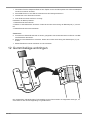
12 Gummibeläge anbringen
Die mitgelieferten selbstklebenden Gummibeläge an den Rohrschellen wie abgebildet anbringen, um
einen festeren Sitz der Montagestange zu gewährleisten.
Seite wird geladen ...
Seite wird geladen ...
Seite wird geladen ...
Seite wird geladen ...
Seite wird geladen ...
Seite wird geladen ...
Seite wird geladen ...
Seite wird geladen ...
-
 1
1
-
 2
2
-
 3
3
-
 4
4
-
 5
5
-
 6
6
-
 7
7
-
 8
8
-
 9
9
-
 10
10
-
 11
11
-
 12
12
-
 13
13
-
 14
14
-
 15
15
-
 16
16
-
 17
17
-
 18
18
-
 19
19
-
 20
20
-
 21
21
-
 22
22
-
 23
23
-
 24
24
-
 25
25
-
 26
26
-
 27
27
-
 28
28


Bresser Weather Center WTW 5in1 Bedienungsanleitung
- Kategorie
- Wetterstationen
- Typ
- Bedienungsanleitung
- Dieses Handbuch eignet sich auch für
in anderen Sprachen
Verwandte Artikel
-
Bresser 7902585 Bedienungsanleitung
-
Bresser 7902580 Bedienungsanleitung
-
Bresser 7002586 Bedienungsanleitung
-
-
-
-
-
-
-
Andere Dokumente
-
 Explore Scientific WSX3001000000 Bedienungsanleitung
-
National Geographic 9080600 Bedienungsanleitung
-
 Explore Scientific WSX3001000000 Bedienungsanleitung
-
-
Renkforce Thermo-hygrometer Bedienungsanleitung
-
 Froggit IP Observer WH2600 SE Operating Instructions Manual


