Makita DLS600 Benutzerhandbuch
- Kategorie
- Gehrungssägen
- Typ
- Benutzerhandbuch

DLS600
EN Cordless Compound
Miter Saw INSTRUCTION MANUAL 12
FR Scie à coupe d’onglet mixte
sans Fil MANUEL D’INSTRUCTIONS 26
DE Akku Gehrungs-und
Kappsäge BETRIEBSANLEITUNG 41
IT Troncatrice composita a
batteria ISTRUZIONI PER L’USO 57
NL Accu-afkortverstekzaag GEBRUIKSAANWIJZING 72
ES Sierra de Inglete Inalámbrica MANUAL DE
INSTRUCCIONES 87
PT Serra de Esquadria a Bateria MANUAL DE INSTRUÇÕES 102
DA Akku kombineret geringssav BRUGSANVISNING 117
EL
131
TR
Testere KULLANMA KILAVUZU 147

2
Fig.1
1
2
3
4
5
6
9
10
11
12
13
14
15
7
8
8
Fig.2

3
16
17
18
19
20
21
22
23
24
Fig.3
1
Fig.4
1
2
3
Fig.5
1
Fig.6
1
2
Fig.7

4
1
Fig.8
1
Fig.9
1
Fig.10
1
Fig.11
22
Fig.12
Fig.13
1 1
3
45
3
2 2
Fig.14
1
Fig.15

5
1
Fig.16
Fig.17
1
Fig.18
1
2
Fig.19
1
23
4
Fig.20
1
Fig.21
1
2
Fig.22
1
Fig.23

6
1
Fig.24
1 2
Fig.25
1 2
Fig.26
1
3
2
Fig.27
2
1
Fig.28
1
Fig.29
1
Fig.30
A
B
Fig.31

7
12
Fig.32
1
Fig.33
4
1
2
3
Fig.34
1
23
Fig.35
123
45
6
Fig.36
1
2
2
Fig.37

8
123
45
Fig.38
123
4
5
6
Fig.39
123
45
6
Fig.40
1
2
3
Fig.41
Fig.42
12
Fig.43
12
3
4
3
5
6
7
Fig.44
2
1
2
Fig.45

9
Fig.46
Fig.47
1
2
4
35
Fig.48
1
2
3
Fig.49
1
Fig.50
Fig.51
1
23
4
Fig.52
1
2
Fig.53

10
1
2
Fig.54
12 3
Fig.55
1
3
2
Fig.56
1
2
Fig.57
1
2
3
Fig.58
1
2
3
Fig.59
12
3
Fig.60
1
2
Fig.61

11
1
Fig.62
1
Fig.63
1
2
3
45
Fig.64
1
2
3
4
Fig.65
1
Fig.66
1
Fig.67

12 ENGLISH
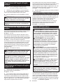
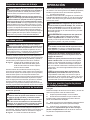
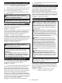
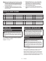
ENGLISH (Original instructions)
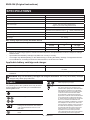
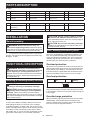
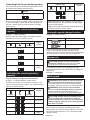
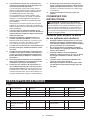
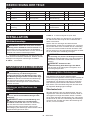
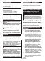
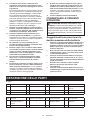
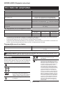
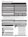
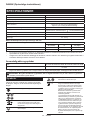
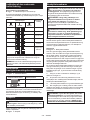
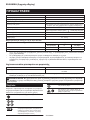
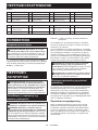
SPECIFICATIONS
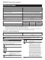
Model: DLS600
Blade diameter 165 mm
Hole (arbor) diameter 20 mm
Max. miter angle Left 52°, Right 52°
Max. bevel angle Left 45° (46° when using release lever),
Right 45° (46° when using release lever)
No load speed 5,000 min-1
Laser type
Red Laser 650 nm, Maximum output 1.6mW ( Laser Class 2M )
Dimensions (L x W x H) 340 mm x 400 mm x 440 mm
Rated voltage D.C. 18 V
Net weight 6.3 - 6.6 kg
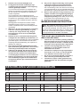
Max. Cutting capacities (H x W) with blade 165 mm
Miter angle Bevel angle
45° (left) 0° 45° (right)
0° 30 mm x 92 mm 46 mm x 92 mm 15 mm x 92 mm
45° (left and right) 30 mm x 65 mm 46 mm x 65 mm 15 mm x 65 mm
without notice.
-
est combinations, according to EPTA-Procedure 01/2014, are shown in the table.
Battery cartridge BL1815N / BL1820B / BL1830B / BL1840B / BL1850B / BL1860B
Charger DC18RC / DC18RD / DC18RE / DC18SD / DC18SE / DC18SF /
DC18SH
• Some of the battery cartridges and chargers listed above may not be available depending on your region of
residence.
WARNING: Use of any other battery cartridges
The followings show the symbols which may be used
for the equipment. Be sure that you understand their
meaning before use.
Read instruction manual.
Wear safety glasses.
holding the saw head down, after making
cuts, until the blade has come to a com-
plete stop.
blade.
Never look into the laser beam. Direct laser
Ni-MH
Li-ion
Only for EU countries
Due to the presence of hazardous com-
ponents in the equipment, waste electrical
and electronic equipment, accumulators
and batteries may have a negative impact
on the environment and human health.
Do not dispose of electrical and electronic
appliances or batteries with household waste!
In accordance with the European Directive
on waste electrical and electronic equipment
and on accumulators and batteries and
waste accumulators and batteries, as well as
their adaptation to national law, waste elec-
trical equipment, batteries and accumulators
should be stored separately and delivered
to a separate collection point for municipal
waste, operating in accordance with the
regulations on environmental protection.
This is indicated by the symbol of the crossed-
out wheeled bin placed on the equipment.

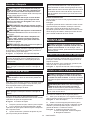
13 ENGLISH
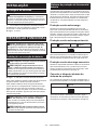
Intended use
The tool is intended for accurate straight and miter
cutting in wood. With appropriate saw blades, aluminum
can also be sawed.
Do not use the saw to cut other than wood, aluminum or
similar materials.
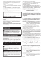
Noise
The typical A-weighted noise level determined accord-
ing to EN62841-3-9:
Sound pressure level (LpA) : 90 dB(A)
Sound power level (LWA) : 97 dB (A)
Uncertainty (K) : 3 dB(A)
NOTE:
The declared noise emission value(s) has been
measured in accordance with a standard test method
and may be used for comparing one tool with another.
NOTE:
The declared noise emission value(s) may
also be used in a preliminary assessment of exposure.
WARNING: Wear ear protection.
WARNING:
The noise emission during actual
WARNING:
to protect the operator that are based on an estima-
tion of exposure in the actual conditions of use (tak-
it is running idle in addition to the trigger time).
Vibration
The vibration total value (tri-axial vector sum) deter-
mined according to EN62841-3-9:
Vibration emission (ah) : 2.5 m/s2 or less
Uncertainty (K) : 1.5 m/s2
NOTE: The declared vibration total value(s) has been
measured in accordance with a standard test method
and may be used for comparing one tool with another.
NOTE: The declared vibration total value(s) may also
be used in a preliminary assessment of exposure.
WARNING:
The vibration emission during actual
-
WARNING: -
sures to protect the operator that are based on an
estimation of exposure in the actual conditions of
use (taking account of all parts of the operating
trigger time).
For European countries only
The EC declaration of conformity is included as Annex A
to this instruction manual.
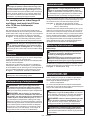
SAFETY WARNINGS
WARNING: -
with this power tool. Failure to follow all instructions
Save all warnings and instruc-
tions for future reference.
The term "power tool" in the warnings refers to your
mains-operated (corded) power tool or battery-operated
(cordless) power tool.
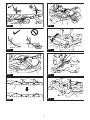
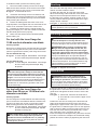
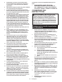
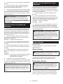
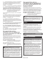
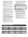
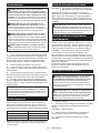
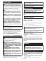
1. Mitre saws are intended to cut wood or wood-
-
Abrasive dust
causes moving parts such as the lower guard to
lower guard, the kerf insert and other plastic parts.
2. Use clamps to support the workpiece when-
ever possible. If supporting the workpiece
least 100 mm from either side of the saw blade.
Do not use this saw to cut pieces that are too
If your hand is placed too close to the saw blade,
contact.
3.
clamped or held against both the fence and the
table. Do not feed the workpiece into the blade
Unrestrained
or moving workpieces could be thrown at high
4.
of cutting either in front or behind the saw
blade. Supporting the workpiece "cross handed"
i.e. holding the workpiece to the right of the saw
blade with your left hand or vice versa is very
dangerous.
Fig.1
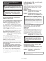
5. Do not reach behind the fence with either hand
closer than 100 mm from either side of the saw
reason while the blade is spinning. The proxim-
ity of the spinning saw blade to your hand may not
6.
the outside bowed face toward the fence.
the line of the cut. Bent or warped workpieces
can twist or shift and may cause binding on the
spinning saw blade while cutting. There should be

14 ENGLISH
7. Do not use the saw until the table is clear of all
-
piece. Small debris or loose pieces of wood or
be thrown with high speed.
8.
Stacked multiple
workpieces cannot be adequately clamped or braced
and may bind on the blade or shift during cutting.
9. Ensure the mitre saw is mounted or placed on
A level
saw becoming unstable.
10.
workpiece and will not interfere with the blade
Without turning the tool
"ON" and with no workpiece on the table, move
the saw blade through a complete simulated cut to
assure there will be no interference or danger of
cutting the fence.
11. Provide adequate support such as table exten-
wider or longer than the table top. Workpieces
longer or wider than the mitre saw table can tip
workpiece tips, it can lift the lower guard or be
thrown by the spinning blade.
12. Do not use another person as a substitute for
a table extension or as additional support.
Unstable support for the workpiece can cause the
blade to bind or the workpiece to shift during the
cutting operation pulling you and the helper into
the spinning blade.
13.
saw blade.
and thrown violently.
14.
or tubing. Rods have a tendency to roll while
being cut, causing the blade to "bite" and pull the
work with your hand into the blade.
15. Let the blade reach full speed before contact-
ing the workpiece. This will reduce the risk of the
workpiece being thrown.
16.
parts to stop and disconnect the plug from
pack. Then work to free the jammed material.
cause loss of control or damage to the mitre saw.
17.
hold the saw head down and wait for the blade
Reaching with your hand near the coasting blade
is dangerous.
18. -
plete cut or when releasing the switch before
-
tion. The braking action of the saw may cause
the saw head to be suddenly pulled downward,
19.
-
ual.
the proper guarding of the blade or guard opera-
20.
a speed equal or higher than the speed marked
on the tool.
21.
aluminum or similar materials.
22.
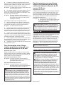
Additional instructions
1. Make workshop kid proof with padlocks.
2. Never stand on the tool.
occur if the tool is tipped or if the cutting tool is
unintentionally contacted.
3. Never leave the tool running unattended. Turn
to a complete stop.
4. Do not operate saw without guards in place.
Check blade guard for proper closing before
each use. Do not operate saw if blade guard
Never clamp or tie the blade guard into the
open position.
5. Keep hands out of path of saw blade. Avoid
6.
7. Stopper pin which locks the cutter head down
8. -
age before operation. Replace cracked or dam-
hardened on blades slows saw and increases
Never use gasoline to clean blade.
9.
10.
-
these parts could result in blade breakage.
11.
secured so it will not move during operation.
Use the holes in the base to fasten the saw to a
stable work platform or bench. NEVER use tool
where operator positioning would be awkward.
12. Make sure the shaft lock is released before the
switch is turned on.
13. Be sure that the blade does not contact the
turn base in the lowest position.
14.
stopping.
15. Make sure the blade is not contacting the
workpiece before the switch is turned on.
16.
let it run for a while. Watch for vibration or
wobbling that could indicate poor installation

15 ENGLISH
17. -
thing abnormal.
18. Do not attempt to lock the trigger in the "ON"
position.
19.
manual. Use of improper accessories such as
20.
be toxic. Take caution to prevent dust inhala-
tion and skin contact. Follow material supplier
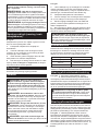
1.
BEAM OR VIEW DIRECTLY WITH OPTICAL
SAVE THESE INSTRUCTIONS.
WARNING:
with product (gained from repeated use) replace
1.
-
2.
cartridge.
or explosion.
3.
and even an explosion.
4.
out with clear water and seek medical atten-
5.
(1) -
ductive material.
(2) -
tainer with other metal objects such as
(3)
or rain.
breakdown.
6. -
reach or exceed 50 °C (122 °F).
7.
8.
Such conduct may result in a
9.
10.
The contained lithium-ion batteries are subject to
the Dangerous Goods Legislation requirements.
For commercial transports e.g. by third parties,
forwarding agents, special requirement on pack-
aging and labeling must be observed.
For preparation of the item being shipped, consult-
ing an expert for hazardous material is required.
Please also observe possibly more detailed
national regulations.
battery in such a manner that it cannot move
around in the packaging.
11.
it from the tool and dispose of it in a safe
12.
Installing the batteries to
-
sive heat, explosion, or leak of electrolyte.
13.
14.
take on heat which can cause burns or low
-
15. Do not touch the terminal of the tool imme-
cause burns.
16.
cartridge.
burst and malfunction of the tool or battery car-
17. Unless the tool supports the use near
-
cal power lines. It may result in a malfunction or
breakdown of the tool or battery cartridge.
18.
SAVE THESE INSTRUCTIONS.
CAUTION:
Use of non-genuine Makita batteries, or batteries that
have been altered, may result in the battery bursting
also void the Makita warranty for the Makita tool and
charger.
Tips for maintaining maximum
1.
less tool power.
2.
3.
-
ture at 10 °C - 40 °C (50 °F - 104 °F). Let a hot
4.
it from the tool or the charger.
5.
it for a long period (more than six months).

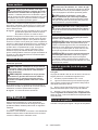
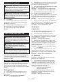
16 ENGLISH
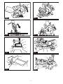
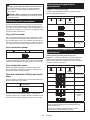
PARTS DESCRIPTION
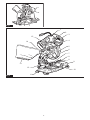
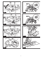
Fig.2
1 2Switch trigger 3Handle 4Blade case
5Blade 6Blade guard 7Sub-fence 8Small sub-fence
9Base 10 Turn base 11 Guide fence 12 Vertical vice
13 Dust bag 14 Dust nozzle 15 Center cover - -
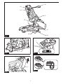
Fig.3
16 Lamp 17 Battery cartridge 18 Hex wrench 19 Release lever
20 Lever (for bevel angle
21 Kerf board 22 23 Lamp switch
24 Laser switch ------
INSTALLATION
Bench mounting
WARNING: Ensure that the tool does not
move on the supporting surface. Movement of the
miter saw on the supporting surface while cutting may
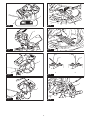
1.
Fix the base to a level and stable surface, screwing with
Fig.4: 1. Bolt
FUNCTIONAL DESCRIPTION
WARNING:
before adjusting or checking the functions on
the tool.
accidental start-up.
CAUTION:
CAUTION: -
cartridge. Failure to hold the tool and the battery
and result in damage to the tool and battery cartridge
Fig.5: 1. Red indicator 2. Button 3. Battery cartridge
To remove the battery cartridge, slide it from the tool
while sliding the button on the front of the cartridge.
To install the battery cartridge, align the tongue on the
battery cartridge with the groove in the housing and slip
it into place. Insert it all the way until it locks in place
with a little click. If you can see the red indicator on the
upper side of the button, it is not locked completely.
CAUTION:
If not,
you or someone around you.
CAUTION:
If the cartridge does not slide in easily, it is
not being inserted correctly.
The tool is equipped with a tool/battery protection sys-
motor to extend tool and battery life. The tool will auto-
matically stop during operation if the tool or battery is
placed under one of the following conditions:
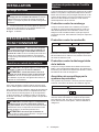
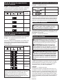
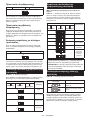
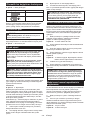
Overload protection
When the tool is operated in a manner that causes it to
draw an abnormally high current, the tool automatically
stops without any indication. In this situation, turn the
become overloaded. Then turn the tool on to restart.
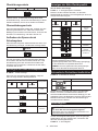
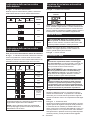
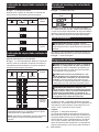
Overheat protection
On Blinking
When the tool is overheated, the tool stops automati-
cally, and the battery indicator blinks about 60 seconds.
In this situation, let the tool cool down before turning the
tool on again.
Overdischarge protection
When the battery capacity becomes low, the tool stops
automatically. If the product does not operate even
when the switches are operated, remove the batteries
from the tool and charge the batteries.

17 ENGLISH
If the protection system is activated repeatedly, the tool
is locked and the battery indicator blinks.
Blinking
which is activating the protection system, and then turn
on the switch again. If the tool does not work after turn-
ing on the switch again, remove the battery cartridge
and charge it.
Fig.6: 1. Battery indicator
When you pull the switch trigger, the battery indicator
indicates the remaining battery capacity.
Remaining
On Blinking
50% to 100%
20% to 50%
0% to 20%
Charge the
battery
Only for battery cartridges with the indicator
Fig.7: 1. Indicator lamps 2. Check button
Press the check button on the battery cartridge to indi-
cate the remaining battery capacity. The indicator lamps
light up for a few seconds.
Indicator lamps Remaining
Lighted Blinking
75% to 100%
50% to 75%
25% to 50%
0% to 25%
Charge the
battery.
Indicator lamps Remaining
Lighted Blinking
The battery
may have
malfunctioned.
NOTE: Depending on the conditions of use and the
from the actual capacity.
NOTE:
the battery protection system works.
Automatic speed change function
Fig.8: 1. Mode indicator
Mode indicator status Operation mode
High speed mode
High torque mode
This tool has "high speed mode" and "high torque
mode". It automatically changes operation mode
depending on the work load. When mode indicator lights
up during operation, the tool is in high torque mode.
Stopper pin
CAUTION:
releasing the stopper pin. Otherwise the handle
To release the stopper pin, keep applying a slight
downward pressure on the handle and then pulling the
stopper pin.
Fig.9: 1. Stopper pin
Blade guard
WARNING: Never defeat or remove the blade
guard or the spring which attaches to the guard.
An exposed blade as a result of defeated guarding
WARNING: Never use the tool if the blade
Operation of the tool with a damaged, faulty or
CAUTION:
in good condition for safe operation. Stop the
of the blade guard. Check to assure spring loaded
return action of guard.
Fig.10: 1. Blade guard
When lowering the handle, the blade guard raises
automatically. The guard is spring loaded so it returns to
its original position when the cut is completed and the
handle is raised.

18 ENGLISH
Cleaning
Fig.11: 1. Blade guard
If the transparent blade guard becomes dirty, or saw-
dust adheres to it in such a way that the blade and/or
workpiece is no longer easily visible, remove the battery
cartridge and clean the guard carefully with a damp
cloth. Do not use solvents or any petroleum-based
cleaners on the plastic guard because this may cause
damage to the guard.
For cleaning, raise the blade guard by referring to
"Installing or removing saw blade".
After cleaning, make sure to return the blade and center
cover and tighten the hex socket bolt.
1.
battery cartridges are removed.
2. Turn the hex socket bolt counterclockwise using
the supplied hex wrench with holding the center cover.
3. Raise the blade guard and center cover.
4. When cleaning is complete, return the center
cover and tighten the hex socket bolt by performing the
steps above in reverse.
WARNING: Do not remove spring holding
blade guard. If guard becomes damaged in course
of time or UV light exposure, contact a Makita ser-
vice center for replacement. DO NOT DEFEAT OR
REMOVE GUARD.
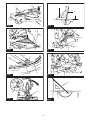
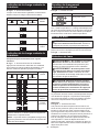
Positioning kerf board
This tool is provided with the kerf boards in the turn
base to minimize tearing on the exit side of a cut. The
kerf boards as follows:
1. Make sure to remove the battery cartridge. Then,
loosen all the screws (2 each on left and right) securing
the kerf boards.
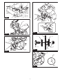
Fig.12: 1. Kerf board 2. Screw
2. Re-tighten them only to the extent that the kerf
boards can still be easily moved by hand.
3. Lower the handle fully and push in the stopper pin
to lock the handle in the lowered position.
4.
contact the sides of the blade teeth.
Fig.13
Fig.14: 1. Saw blade 2. Blade teeth 3. Kerf board
4. Left bevel cut 5. Straight cut
5.
6. -
per pin and raise the handle. Then tighten all the screws
securely.
NOTICE: After setting the bevel angle ensure
Correct
support of the workpiece and minimizing workpiece
tear out.
Maintaining maximum cutting
cutting capacity for a 165 mm saw blade.
When installing a new blade, always check the lower
follows:
1. Remove the battery cartridge. Lower the handle
completely.
2. -
ing bolt until the saw blade comes slightly below the
cross section of the guide fence and the top surface of
the turn base.
Fig.15: 1.
Fig.16: 1. Guide fence
3. Rotate the blade by hand while holding the handle
all the way down to be sure that the blade does not
necessary.
WARNING: After installing a new blade and
the lower base when the handle is lowered com-
If a blade makes contact with the base, it may
Fig.17
Sub-fence
This tool is equipped with the sub-fence and small
sub-fences.
Sub-fence
WARNING:
performing bevel cuts. Failure to do so may cause
Fig.18: 1. Sub-fence
When performing cuts except for bevel cuts, use the
sub-fence to support the workpiece.
Small sub-fence
CAUTION:
fold the small sub-fences. Otherwise, they may
contact the blade or a part of the tool, and may result
Fig.19: 1. Small sub-fence 2. Scale
upward to support the workpiece. The guide fence has
a scale of 10 mm interval.

19 ENGLISH
Adjusting the miter angle
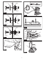
Fig.20: 1. Fixing screw 2. Turn base 3. Miter scale
4. Pointer
1.
2.
and the miter scale as a guide.
3.
CAUTION:
NOTICE:
Adjusting the bevel angle
the tool downward.
Fig.21: 1. Lever
To tilt the blade to the left, hold the handle and tilt the
saw head. Use the bevel scale and the pointer as a
saw head.
Fig.22: 1. Pointer 2. Bevel scale
To tilt the blade to the right, hold the handle and tilt the
saw head to the left slightly, and push the release but-
ton. With the release button pressed, tilt the saw blade
saw head.
Fig.23: 1. Release button
CAUTION:
NOTICE:
NOTICE:
as explained in the "Positioning kerf boards"
section.
Setting 46° bevel angle
1. Loosen the lever and tilt the blade to the left or
right fully.
Fig.24: 1. Lever
2. To tilt the blade to the left, hold the handle and tilt
the saw head to the right slightly, and then move the
release lever to the direction of the arrow. The bevel
saw head while moving the release lever.
To tilt the blade to the right, hold the handle and tilt the
saw head to the left slightly, and then move the release
lever to the direction of the arrow. The bevel angle can
while moving the release lever.
Fig.25: 1. Lever 2. Release lever
3.
head.
Adjusting the lever position
If the lever does not provide full tightening in course of
time, change the position of the lever. The lever can be
repositioned at every 30° angle.
Loosen and remove the screw that secures the lever.
Remove the lever and install it again so that it points
slightly above the horizontal. Then, tighten the lever
Fig.26: 1. Lever 2. Screw
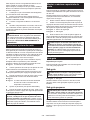
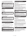
Switch action
WARNING: -
the "OFF" position when released. Operating a tool
with a switch that does not actuate properly can lead
WARNING:
operative switch trigger. Any tool with an inoper-
ative switch is HIGHLY DANGEROUS and must be
repaired before further usage or serious personal
WARNING: For your safety, this tool is equipped
unintended starting. NEVER use the tool if it runs
A switch in need of
repair may result in unintentional operation and seri-
center for proper repairs BEFORE further usage.
WARNING:
A switch with
NOTICE: Do not pull the switch trigger hard
This can
cause switch breakage.
To prevent the switch trigger from being accidentally
Release the switch trigger to stop.
Fig.27: 1.2. Hole for padlock
3. Switch trigger

20 ENGLISH
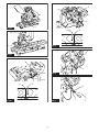
Lighting up the lamp
CAUTION: This is not a rainproof light. Do not
wash the light in water or use it in a rain or a wet
area. Such a conduct can cause an electric shock
and fume.
CAUTION:
This may cause a burn to a human body.
CAUTION:
CAUTION: Do not keep casting the beam of
This can cause your eyes to
be hurt.
CAUTION:
CAUTION: Do not look in the light or see the
To turn on the lamp, press the upper position (I) of the
of the switch.
Fig.28: 1. Lamp 2. Lamp switch
NOTE:
the lamp. Be careful not to scratch the lens of lamp, or
it may lower the illumination.
NOTE:
switch consumes the battery power.
Laser beam action
CAUTION: Never look into the laser beam.
To turn on the laser beam, press the upper position (I)
position (0) of the switch.
Fig.29: 1. Laser switch
NOTE:
switch consumes the battery power.
Laser line can be shifted to either the left or right side
as follows.
Fig.30: 1.
1.
counterclockwise.
2.
3.
where it stops sliding.
NOTE:
positioned within 1 mm from the side surface of the
circular saw blade (cutting position).
NOTE: When laser line appears dim and hard to see
because of direct sunlight, relocate the work area to a
place where there is less direct sunlight.
Aligning the laser line
Align the cutting line on your workpiece with the laser line.
Fig.31
A) When you want to obtain the correct size on the left
side of workpiece, shift the laser line to the left of the
circular saw blade.
B) When you want to obtain the correct size on the right
side of workpiece, shift the laser line to the right of the
circular saw blade.
ASSEMBLY
WARNING:
before working on the tool.
remove the battery cartridge may result in serious
Hex wrench storage
wrench is needed it can be pulled out of the wrench holder.
After using the hex wrench it can be stored by returning
it to the wrench holder.
Fig.32: 1. Wrench holder 2. Hex wrench
Installing or removing saw blade
WARNING:
before installing or removing the blade. Accidental
start up of the tool may result in serious personal
CAUTION:
provided to install or remove the blade. Failure
tightening of the hex socket bolt. This could cause
To remove the blade, perform the following steps:
1. Release the stopper pin, and then lock the handle
in the raised position by pushing in the stopper pin.
Fig.33: 1. Stopper pin
2. Use the hex wrench to loosen the hex socket bolt
holding the center cover by turning it counterclockwise.
Then, raise the blade guard and center cover.
Fig.34: 1. Center cover 2. Hex socket bolt 3. Hex
wrench 4. Blade guard
3.
Press the shaft lock to lock the spindle and use the hex
wrench to loosen the hex socket bolt clockwise. Then remove
Fig.35:
1. Shaft lock 2. Hex socket bolt 3.
4. -
dle with its blade mounting part facing the blade. If the
the machine.
Fig.36: 1.2. Saw blade 3.
4. Hex socket bolt (left-handed) 5. Spindle
6. Blade mounting part
Seite laden ...
Seite laden ...
Seite laden ...
Seite laden ...
Seite laden ...
Seite laden ...
Seite laden ...
Seite laden ...
Seite laden ...
Seite laden ...
Seite laden ...
Seite laden ...
Seite laden ...
Seite laden ...
Seite laden ...
Seite laden ...
Seite laden ...
Seite laden ...
Seite laden ...
Seite laden ...
Seite laden ...
Seite laden ...
Seite laden ...
Seite laden ...
Seite laden ...
Seite laden ...
Seite laden ...
Seite laden ...
Seite laden ...
Seite laden ...
Seite laden ...
Seite laden ...
Seite laden ...
Seite laden ...
Seite laden ...
Seite laden ...
Seite laden ...
Seite laden ...
Seite laden ...
Seite laden ...
Seite laden ...
Seite laden ...
Seite laden ...
Seite laden ...
Seite laden ...
Seite laden ...
Seite laden ...
Seite laden ...
Seite laden ...
Seite laden ...
Seite laden ...
Seite laden ...
Seite laden ...
Seite laden ...
Seite laden ...
Seite laden ...
Seite laden ...
Seite laden ...
Seite laden ...
Seite laden ...
Seite laden ...
Seite laden ...
Seite laden ...
Seite laden ...
Seite laden ...
Seite laden ...
Seite laden ...
Seite laden ...
Seite laden ...
Seite laden ...
Seite laden ...
Seite laden ...
Seite laden ...
Seite laden ...
Seite laden ...
Seite laden ...
Seite laden ...
Seite laden ...
Seite laden ...
Seite laden ...
Seite laden ...
Seite laden ...
Seite laden ...
Seite laden ...
Seite laden ...
Seite laden ...
Seite laden ...
Seite laden ...
Seite laden ...
Seite laden ...
Seite laden ...
Seite laden ...
Seite laden ...
Seite laden ...
Seite laden ...
Seite laden ...
Seite laden ...
Seite laden ...
Seite laden ...
Seite laden ...
Seite laden ...
Seite laden ...
Seite laden ...
Seite laden ...
Seite laden ...
Seite laden ...
Seite laden ...
Seite laden ...
Seite laden ...
Seite laden ...
Seite laden ...
Seite laden ...
Seite laden ...
Seite laden ...
Seite laden ...
Seite laden ...
Seite laden ...
Seite laden ...
Seite laden ...
Seite laden ...
Seite laden ...
Seite laden ...
Seite laden ...
Seite laden ...
Seite laden ...
Seite laden ...
Seite laden ...
Seite laden ...
Seite laden ...
Seite laden ...
Seite laden ...
Seite laden ...
Seite laden ...
Seite laden ...
Seite laden ...
Seite laden ...
Seite laden ...
Seite laden ...
Seite laden ...
Seite laden ...
-
 1
1
-
 2
2
-
 3
3
-
 4
4
-
 5
5
-
 6
6
-
 7
7
-
 8
8
-
 9
9
-
 10
10
-
 11
11
-
 12
12
-
 13
13
-
 14
14
-
 15
15
-
 16
16
-
 17
17
-
 18
18
-
 19
19
-
 20
20
-
 21
21
-
 22
22
-
 23
23
-
 24
24
-
 25
25
-
 26
26
-
 27
27
-
 28
28
-
 29
29
-
 30
30
-
 31
31
-
 32
32
-
 33
33
-
 34
34
-
 35
35
-
 36
36
-
 37
37
-
 38
38
-
 39
39
-
 40
40
-
 41
41
-
 42
42
-
 43
43
-
 44
44
-
 45
45
-
 46
46
-
 47
47
-
 48
48
-
 49
49
-
 50
50
-
 51
51
-
 52
52
-
 53
53
-
 54
54
-
 55
55
-
 56
56
-
 57
57
-
 58
58
-
 59
59
-
 60
60
-
 61
61
-
 62
62
-
 63
63
-
 64
64
-
 65
65
-
 66
66
-
 67
67
-
 68
68
-
 69
69
-
 70
70
-
 71
71
-
 72
72
-
 73
73
-
 74
74
-
 75
75
-
 76
76
-
 77
77
-
 78
78
-
 79
79
-
 80
80
-
 81
81
-
 82
82
-
 83
83
-
 84
84
-
 85
85
-
 86
86
-
 87
87
-
 88
88
-
 89
89
-
 90
90
-
 91
91
-
 92
92
-
 93
93
-
 94
94
-
 95
95
-
 96
96
-
 97
97
-
 98
98
-
 99
99
-
 100
100
-
 101
101
-
 102
102
-
 103
103
-
 104
104
-
 105
105
-
 106
106
-
 107
107
-
 108
108
-
 109
109
-
 110
110
-
 111
111
-
 112
112
-
 113
113
-
 114
114
-
 115
115
-
 116
116
-
 117
117
-
 118
118
-
 119
119
-
 120
120
-
 121
121
-
 122
122
-
 123
123
-
 124
124
-
 125
125
-
 126
126
-
 127
127
-
 128
128
-
 129
129
-
 130
130
-
 131
131
-
 132
132
-
 133
133
-
 134
134
-
 135
135
-
 136
136
-
 137
137
-
 138
138
-
 139
139
-
 140
140
-
 141
141
-
 142
142
-
 143
143
-
 144
144
-
 145
145
-
 146
146
-
 147
147
-
 148
148
-
 149
149
-
 150
150
-
 151
151
-
 152
152
-
 153
153
-
 154
154
-
 155
155
-
 156
156
-
 157
157
-
 158
158
-
 159
159
-
 160
160


Makita DLS600 Benutzerhandbuch
- Kategorie
- Gehrungssägen
- Typ
- Benutzerhandbuch
in anderen Sprachen
- français: Makita DLS600 Manuel utilisateur
- español: Makita DLS600 Manual de usuario
- italiano: Makita DLS600 Manuale utente
- Nederlands: Makita DLS600 Handleiding
- português: Makita DLS600 Manual do usuário
- dansk: Makita DLS600 Brugermanual
- Türkçe: Makita DLS600 Kullanım kılavuzu
Verwandte Papiere
-
Makita DLS714 Benutzerhandbuch
-
Makita M2300 Benutzerhandbuch
-
Makita DCS552 Benutzerhandbuch
-
Makita LS1018 Slide Compound Miter Saw Benutzerhandbuch
-
Makita DLS111 Benutzerhandbuch
-
Makita HS011G Benutzerhandbuch
-
Makita CS002G Benutzerhandbuch
-
Makita DHS680 Benutzerhandbuch
-
Makita DLS713 Bedienungsanleitung
-