Seite wird geladen ...

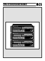
CPA-5120C/5240C/5480C
2
Read all safety instruction before operating.
1. Install equipment as follow condition:
- Install at flat place, not bending curved.
- Do not install near the water and moisture.
- Locate power amplifier away from heat source.
- Do not drop objects or spill liquids into the inside of
amplifier.
2. Keep in mind the following when connecting amplifier.
- Connect the amplifier after reading of manuals.
- Connect each connection of amplifier perfectly, if not, it
maybe caused hum, damage, electric shock in case of
misconnecting.
- To prevent electric shock, do not open top cover.
- Connect the power cord with safety after check of AC
power.
SAFETY INSTRUCTIONS
Vor Inbetriebnahme des Geräts bitten wir Sie, die Sicherheits-
hinweise aufmerksam zu lesen.
1. Installation nach folgenden Richtlinien:
- Stellen Sie den Verstärker immer auf eine ebene und
stabile Unterfläche.
- Wählen Sie eine trockene Umgebung und stellen sie
keine Flüssigkeiten auf das Gerät.
- Vermeiden Sie die Nähe von Heizungen und anderen
Hitzequellen.
2. Beachten Sie folgendes, wenn Sie den Verstärker an-
schließen.
- Lesen Sie zuerst die Betriebsanleitung
- Öffnen Sie niemals das Gehäuse des Geräts ohne den
Netzstecker zu ziehen.
- Schließen Sie das Gerät nur an 230 V Netzspannung
oder 24 V/DC Notstromversorgung.
SICHERHEITSHINWEISE
FEATURES
1. Rated outputs: 120 W / 240 W / 480 W.
2. "Voice priority" on input 1.
3. Chime and Siren.
4. Mic/Line switch for input 2 - 4.
5. Phantom Power.
6. Pre out / Amp in for extensions with other amplifiers.
7. Slot for modules CR-10, TP-10, CP-10, DM-10, CDP-10
and CDR-10.
8. 5 speaker zone attenuator.
MERKMALE
1. In 3 Leistungsklassen verfügbar: 120 W / 240W / 480 W.
2. Eingang Mic1 mit elektronischer Priorität.
3. Gong und Sirene vorhanden
4. Eingänge 2 - 4 von Mic auf Line umschaltbar.
5. Amp In und Pre Out zur Kaskadierung.
6. Zuschaltbare Phantom Power für Mic.
7. Leerfeld für Tonträgermodule CR-10, TP-10, CP-10, DM-10,
CDP-10 u. CDR-10.
8. 5 einzeln schalt- und regelbare 100 V- bzw. 70V Lautspre-
cherkreise.

CPA-5120C/5240C/5480C
3
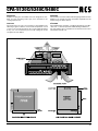
MOUNTING
Amplifier racking size CPA-5000 series are designed for stan-
dard 19" rack mounting. Please pay close attention to the
cooling requirements.
COOLING
Never block the air vents rear and front of the amplifier. The
following is figure of airflow. Check inside temperature of rack
system so as not to be more than 40°C for the stable operating
in any case, we recommend you to install cooling fan on the
rear panel of rack cabinet.
MONTAGE
Die Verstärker sind mit seitlichen Befestigungswinkeln für den
Einbau in 19" Gestelle versehen. Zusätzlich empfiehlt sich die
Verwendung von Gleitschienen.
KÜHLUNG
Die Luftöffnungen an Vorder- und Rückseite dürfen nicht blo-
ckiert sein, so wird ein optimaler Kühlluftfluß gewährleistet.
Die Verwendung eines zusätzlichen Rack-Lüfters kann unter
Umständen sinnvoll sein.

CPA-5120C/5240C/5480C
4
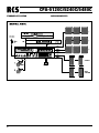
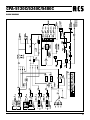
FRONT PANEL CONTROLS VORDERSEITE
1. MIC INPUT JACK OF INPUT 1
This is for only MIC1 input jack which is adjusted by volume
control of input 1 connecting to combo jack in the rear
panel.
Input signal of MIC1 has priority against input 2-4 and AUX
input 5,6,7.
2. VOLUME CONTROLS OF INPUT 1 - 4
This are volume controls of input 1 - 4.
3. VOLUME CONTROL AND SELECTOR SWITCH
- Auxiliary Input Volume Control
This is auxiliary input volume control 5.6.7.
- Auxiliary Input Selector Switch
This is auxiliary input selector switch 5.6.7.
4. MASTER VOLUME CONTROL AND EQ
- Master Volume Control
Master volume control which is adjusting main volume.
- Bass
This control is used for adjusting the low freguency
sound (+/-10 dB at 100 HZ)
- Treble
This control is used for adjusting the high freguency
sound (+/-10 dB at 10 kHZ)
5. LED INDICATOR
- Protect LED Indicator
PROT LED indicator will be turn on, when temperature
on the heat sink is 100°C and input signal is closed for
protection of amplifier.
- Clipping LED Indicator
Be sure to adjust volume control CLIP LED turn on
continuously.
- Output Level VU Meter
These displays indicate the output level of amplifier.
- Power LED Indicator
Power LED indicator will be turn on, when AC Cord plug
in AC socket and Stand-by LED will be turn off, when
push the power switch.
1. MIC1 EINGANG
Dieser frontseitige Mikrofoneingang auf 6,3 mm Klinke ver-
fügt über einen sprachgesteuerten Vorrang gegenüber den
Eingängen 2 - 4 und AUX.
Die Lautstärke des Eingangsignals wird mit dem Regler
INPUT1 bestimmt.
2. LAUTSTÄRKEREGLER
Lautstärkeregler für die Eingänge 2 - 4.
3. REGLER UND WAHLSCHALTER
- Lautstärkeregler für AUX-Eingänge
Lautstärkeregler für Cincheingänge 5, 6 und 7
- AUX-Wahlschalter
Schalter zum Auswählen der Eingänge 5, 6 u. 7.
4. MASTER REGLER
- Master Lautstärkeregler
Master-Regler zum Regeln der Lautstärke.
- Bass
EQ-Masterregler zum Einstellen der Tiefen (+/-10 dB bei
100 HZ)
- Treble
EQ-Masterregler zum Einstellen der Höhen (+/-10 dB
bei 10 kHZ)
5. LED´s
- Protect LED
Die PROT LED zeigt die Überhitzung des Verstärkers
an (100°C), gleichzeitig wird eine Schutzschaltung zum
Schutz des Verstärkers aktiviert
- Clipping LED
Die CLIP LED leuchtet, wenn die Ausgangsspannung
übersteuert wird.
- Level Meter
Level Meter als Anzeige des Signalpegels
- Power LED
Diese LED`S zeigen den Betriebszustand des Verstärkers
an, wenn das Gerät eingeschaltet ist leuchtet die gelbe
LED im Stand-by Betrieb die Grüne.

CPA-5120C/5240C/5480C
5
6. POWER SWITCH
When push the power switch, Power LED will be turn on.
In case of Connection for AC/DC Power sametimes, DC
power will supply automatically when unexpected AC Po-
wer failure. Built in AC remote power control function when
power switch off.
7. CHIME SWITCH
When push the chime switch, Chime signal will be activated.
This is for pre signal or alert signal.
8. PACK SERIES SLOT
This in slot for installation of PACK Series, TP-10, CP-10,
CR-10, CDP-10, CDR-10, DM-10.
9. 5 ZONE ATTENUATORS
You can decrease amplifier output per zone as 5 steps it
consists of 5 speaker zone areas which has a function "OFF"
switch for non broadcasting area.
6. POWER
Ein- und Ausschalter des Verstärkers.
Bei Netzausfall schaltet der Verstärker automatisch auf die
Notstromversorgung um.
Weiterhin kann der Verstärker auch über den "Power Re-
mote" Anschluß eingeschaltet werden.
7. GONG
Taster zur Auslösung des 2-Klanggong.
8. TONTRÄGERLEERFELD
Dieses Leerfeld dient zur Aufnahme folgender Tonträgerm-
odule: TP-10, CP-10, CR-10, CDP-10, CDR-10 und DM-
10
9. LAUTSPRECHER AUSGÄNGE
Die Lautstärke der 5 Lautsprecherkreise kann in 5 Schritten
geregelt werden, weiterhin ist es möglich einen gewünschten
Lautsprecherkreis auszuschalten.

CPA-5120C/5240C/5480C
6
REAR PANEL CONTROLS RÜCKSEITE
1. PHANTOM POWER SWITCHES 1 - 4
Pushing phantom switch when using of balanced condensor
microphone for input 1-4.
2. MIC/LINE SWITCHES 2 - 4
Adjust mic/line level. Input sensitivity for line input is -10
dB when push switch.
Unpushed switch is mic input, sensitivity of mic input is
-50 dB.
3. MIC/LINE INPUT
- MIC/LINE Input Terminals 2-4
Selectable Mic/Line switch for input terminals 2-4.
- Mute/Chime by switch terminals 2-4.
AUX 5, 6, 7 and pack signal will be muted and chime si-
gnal is operated by signal input from external contact.
4. VOLUME CONTROLS
- Chime Volume Control
This control is used for adjusting the chime signal.
- Siren Volume Control
This control is used for adjusting the siren signal.
- Mute Level Volume Control
When the other signal is muted by MIC 1 chime and
siren or when the other signal is muted by Mute/Chime
switch, this control is used for adjusting the muting level
(Variable range: -10 DB till -20 dB)
5. AM/FM ANT INPUT TERMINALS (OPTION)
FM : You connect 75 ohm coaxial cable or 300 ohm feeder
cable according to antennas.
AM : Connect it to the AM terminal in case of using outdoor
antenna.
GND : AM earthing terminal for AM receiption.
6. AMP IN/PRE OUT JACKS
- AMP IN Jack
Feed trough input amp in connection with the output
Pre Out e.g. an equalizer in case of connection to this
jack, only the signal fed in here is reproduced.
1. PHANTOM POWER
Schalter zum Zuschalten der "Phantom Power" bei Verwen-
dung von Kondensatormikrofonen.
2. MIC/LINE UMSCHALTER
Schalter zum Auswählen der Eingangsempfindlichkeit für
MIC oder LINE.
Eingangsempfindlichkeit Line: -10 dB, Eingangsempfind-
lichkeit Mic: -50 dB
3. MIC/LINE EINGÄNGE
- MIC/LINE Eingänge 2-4
Symmetrische Inputs auf Schraubsteckverbinder.
- Vorgong
Zusätzlicher Kontakt für Gong (z.B. durch CPA-10),
welcher Vorrang gegenüber AUX und Modulen hat.
4. LAUTSTÄRKEREGLER
- Gong Lautstärke
Regler zum Einstellen der Gonglautstärke
- Sirene Lautstärke
Regler zum Einstellen der Sirenenlautstärke
- Mute Level Regler
Mit diesem Regler wird der Mute Level im Bereich von
-10 dB bis -20 dB eingestellt.
Dies betrifft den Vorrang durch MIC 1, Gong, Sirene und
Vorgong auf Schraubsteckverbinder.
5. AM/FM ANTENNEN ANSCHLUß (OPTION)
FM : Anschluß für 75 Ohm Koaxialkabel oder eines 300 Ohm
Kabels.
AM : Anschluß für die AM Antenne
GND : Erdung für AM Antenne, als Überspannungsschutz
und zum Vermindern von Störgeräuschen.
6. AMP IN / PRE OUT
- AMP IN
In Verbindung mit dem Pre Out Ausgang kann hier z.B.
ein Equalizer eingeschliffen werden. Es wird dann nur
das hier eingespeiste Signal wiedergegeben.

CPA-5120C/5240C/5480C
7
- PRE OUT Jack
Output pre out in connection with the input Amp In for
inserting e.g. an equalizer the output volume is indepen-
dant of master control.
7. RCA JACKS OF AUX 5 - 7
It is RCA jacks of AUX 5, 6, 7 which can be connected to
CD tuner, cassette deck.
8. COMBO JACKS OF INPUT 1 - 2
Convenient input jack 1 - 2 as a XLR and 1/4" multiful.
9. GROUND/LIFT SWITCH
This switch is for grounding between circuit ground and
chassis ground to avoid problems like a electrical potential
difference.
10. DC POWER INPUT
This is terminal for DC24 V battery power supply.
11. AC POWER REMOTE CONTROL
This is a terminal of AC Power remote control for power
supply to the equipment under AC mains "Off".
- PRE OUT
In Verbindung mit dem Amp In Ausgang kann hier z.B.
ein Equalizer eingeschliffen werden. Die Lautstärke ist
abhängig vom "Master"-Regler.
7. CINCH EINGÄNGE AUX 5 - 7
Eingänge für Geräte mit Line Pegel z.B. CD-Player, Kasset-
ten-Deck u.ä..
8. COMBO EINGÄNGE 1 - 2
Symmetrische Eingänge f. XLR od. 6,3 mm Klinke.
9. GROUND/LIFT SCHALTER
Eventuelle Potentialunterschiede zwischen Geräte- und
Signalmasse können zu Brummschleifen führen, welche
mit dem "Ground Lift" Schalter beseitigt werden.
10. DC 24 V EINGANG
Eingang für 24 V DC Notstromversorgung.
11. "POWER REMOTE"
Ferneinschalten des Verstärkers möglich, wenn der Netz-
schalter auf "Aus" steht.
12. AC Inlet
This is AC power cable, please connect power plug after
main power switch "Off".
Fuse: Built in the PCB FU1
12. AC Power
Anschlußstecker für Kaltgeräte-Netzkabel (im Liefer-
umfang).
Die Sicherung befindet sich auf PCB FU1
CPA-1200
CPA-2400
CPA-4800
T2AH 250 V (55T)
T3,15AH 250 V (55T)
T6,3AH 250 V (55T)
13. DIRECT SPEAKER OUTPUT
This output speaker terminal is direct output signal not via
attenuators.
14. ATT ZONE SPEAKER OUTPUT
Output signal is come out according to attenuated selector
per zone.
15. SIREN REMOTE CONTROL
This is terminal of siren operation by remote when short the
terminal, siren is operating.
16. CHIME REMOTE CONTROL
This is terminal of chime operation by remote when short
the terminal, chime is operating.
17. CHIME ON/OFF SELECTOR OF INPUT 2-4
When shorten chime/mute terminal of input2-4, chime is
operating and signal of AUX 5, 6, 7 and pack is muted.
For the non chime operation remove short bar.
13. LAUTSPRECHER AUSGÄNGE
100 V und 8 Ohm Lautsprecherausgänge, welche nicht von
den 5 Lautstärkereglern (siehe 14) geregelt werden.
14. REGELBARE LAUTSPRECHER AUSGÄNGE
5 Lautsprecherausgänge (100 V od. 70 V), die einzeln, in 5
Schritten, geregelt und ausgeschaltet werden können.
15. SIRENEN FERNBEDIENUNG
Diese Klemme dient zur Fernbedienung der Sirene durch
einen potentialfreien Kontakt.
16. GONG FERNBEDIENUNG
Diese Klemme dient zur Fernbedienung des Gong durch
einen potentialfreien Kontakt.
17. KONTAKT FÜR VORGANG INPUT 2-4
Wenn diese Klemme gebrückt ist (werkseitig), kann durch
die Kontakte Eingang 2-4 der Vorgong ausgelöst werden,
welcher Priorität gegenüber AUX und Modulen hat.
Seite wird geladen ...
Seite wird geladen ...

CPA-5120C/5240C/5480C
10
TECHNICAL
- Input Sensitivity/Impedance INPUT 1: Mic : -50dBu(2.45mV) 5KΩ BAL
INPUT 2-4: Mic: -50dBu(2.45mV) 2KΩ BAL
Line : -10dBu(245mV)200KΩ UNBAL
INPUT 5-7: AUX: -10dBu(245mV) 5KΩ UNBAL
PACK UNIT: -10dBU(245mV) 10KΩ UNBAL
PRE OUT: 0dBu(775mV) 100KΩ UNBAL
AMP IN: 0dBu(775mV) 10KΩ UNBAL
- Rated Output CPA-1200 : 120W(RMS)
CPA-2400 : 240W(RMS)
CPA-4800 : 480W(RMS)
- Direct Output 8 Ω, 100V or 70V
- A.T.T Step (option)
- Frequency response LINE : LESS THAN -3dB(35Hz~19KHz)
MIC : LESS THAN -3dB(200Hz~19KHz)
- Signal to noise ratio(1KHz) MIC : MORE THAN 80dB (”A” WEIGHT)
LINE: MORE THAN 70dB (”A” WEIGHT)
- T.H.D LESS THAN 0.5% (1KHz)
- Tone Control BASS : ±10dB at 100Hz
TREBLE: ±10dB at 10KHz
- Power Consumption CPA-1200: 350W
CPA-2400: 740W CPA-4800: 1480W
- 1/8 Power Current draw 120V/230V CPA-1200: 1.6A/0.8A
CPA-2400: 2.8A/1.4A CPA-4800: 5.6A/3.2A
- 1/3 Power Current draw 120V/230V CPA-1200: 2.4A/1.2A
CPA-2400: 4A/2A CPA-4800: 8.5A/4.7A
- Rated Power Current
draw 120V/230V CPA-1200: 3.6A/1.8A
CPA-2400: 6.4A/3.2A CPA-4800: 14.0A/7.5A
GENERAL
- Power Source(Option) 120V/220V/230V/240VAC 50~60Hz
24VDC
- Dimensions (mm) 430(W) x 133(H) x 352(D)
(inches) 16.9(W) x 5.2(H) x 13.9(D)
- Weight (kg/lbs) CPA-1200 : 14.0/30.9
CPA-2400 : 16.5/36.4 CPA-4800 : 20.0/44.1
NOTE
Specifications and design subject to change without notice for improvements.
Seite wird geladen ...

CPA-5120C/5240C/5480C
Lieferung durch:
Electromagnetic compatibility and low-voltage guidelines: RCS leaves all devices and products, which are subject to the CE guidelines by certified test laboratories test.
By the fact it is guaranteed that you may sell our devices in Germany and in the European Union domestic market without additional checks.
Elektromagnetische Verträglichkeit und Niederspannungsrichtlinien: RCS läßt alle Geräte und Produkte, die den CE-Richtlinien unterliegen durch zertifizierte Prüflabors
testen. Dadurch ist sichergestellt, dass Sie unsere Geräte in Deutschland und im EU-Binnenmarkt ohne zusätzliche Prüfungen verkaufen dürfen.
RCS08.06.2006
-
 1
1
-
 2
2
-
 3
3
-
 4
4
-
 5
5
-
 6
6
-
 7
7
-
 8
8
-
 9
9
-
 10
10
-
 11
11
-
 12
12


RCS CPA-5120C Bedienungsanleitung
- Typ
- Bedienungsanleitung
- Dieses Handbuch eignet sich auch für
in anderen Sprachen
- English: RCS CPA-5120C Owner's manual
Verwandte Artikel
-
RCS CPA-120X-240X Bedienungsanleitung
-
-
-
-
-
-
-
RCS VLZ-6120A-6240A-6480A-6600A Bedienungsanleitung
-
-