Seite wird geladen ...

The data specified above only serve to
describe the product. No statements
concerning a certain condition or suitability
for a certain application can be derived from
our information. The given information does
not release the user from the obligation of
own judgement and verification. It must be
remembered that our products are subject
to a natural process of wear and aging.
An example configuration is depicted on the
title page. The delivered product may thus
vary from that in the illustration.
Translation of the original operating
instructions. The original operating
instructions were created in the German
language.
R961403375–RAW–001–AB/11.2014
Subject to modifications. © All rights
reserved by AVENTICS GmbH, even and
especially in cases of proprietary rights
applications. It may not be reproduced or
given to third parties without its consent.
AVENTICS GmbH
Ulmer Straße 4
30880 Laatzen
Phone +49 (0) 5 11-21 36-949
Fax: +49 (0) 511-21 36-505
www.aventics.com
spareparts@aventics.com
Further addresses:
www.aventics.com/contact
Reparaturanleitung | Repair instruction
Dichtsätze für Drehzylinder, Alte+Neue
Version (new generation)
Seal kits for Rotary cylinder, Old+New
Version (new generation)
Serie TRR
R961403375-RAW-001-AB/11.2014,
Replaces: 26.11.2014, DE/EN
AVENTICS | Serie TRR | 11.2014 1
1
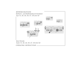
Abwandlung / modification
Drehzylinder, Serie TRR, Neue Version (new generation)/
Rotary cylinder, Series TRR, New Version (new generation)
Seite 2 /
page 2
Drehzylinder, Serie TRR, Alte Version/
Rotary cylinder, Series TRR, Old version
Seite 3 /
page 3

2AVENTICS | Serie TRR | 11.2014
Drehzylinder, Serie TRR, Neue Version (new generation)
Rotary cylinder, Series TRR, New Version (new generation)
Dichtsatzliste für Drehzylinder, Serie TRR, Neue Version (new generation) / Alte Version
Sealing parts list for Rotary cylinder, Series TRR, New Version (new generation) / Old Version
Abbildung 1 / Figure 1
Ø 32 - 1827009736 Ø 40 - 1827009737 Ø 50 - 1827009738 Ø 63 - 1827009739 Ø 80 - 1827009740 Ø 100 - 1827009741
Pos. /
No.
Inhalt /
Content
Stk. / Pcs.
Verwendung New Generation,
Paeck./Abb.1
Application New Generation,
Pack./Fig.1
Verwendung New Generation,
Paeck./Abb.1
Application New Generation,
Pack./Fig.1
10* ANSCHLAGSCHEIBE / STOP DISC ( Ø 32 - Ø 40 ) 2 x x
10* ANSCHLAGSCHEIBE / STOP DISC ( Ø 50 - Ø 100) 1 x x
20 SINTERBUCHSE / SINTERED-METAL BUS 2 x x
30 KOLBENDICHTUNG / PISTON SEALING 2 x x
40 O-RING 2 x
50 DAEMPFUNGSRING / DAMPING RING 2 x
60* ANSCHLAGSCHEIBE / STOP DISC ( Ø 32 - Ø 40 ) - - -
60* ANSCHLAGSCHEIBE / STOP DISC ( Ø 50 - Ø 100) 1 x x
70 DAEMPFUNGSRING / DAMPING RING 2 x
80 EINSATZ / INSERT 2 x
Hinweis / Note
Hinweis: Für Pos. 10* - 60* siehe Abbildung A und B
Note: For Pos. 10* - 60* see figure A and B
12

AVENTICS | Serie TRR | 11.2014 3
Drehzylinder, Serie TRR, Alte Version
Rotary cylinder, Series TRR, Old version
Dichtsatzliste für Drehzylinder, Serie TRR, Alte Version / Neue Version (new generation)
Sealing parts list for Rotary cylinder, Serie TRR, Old Version / New Version (new generation)
Abbildung 2 / Figure 2
Ø 32 - 1827009736 Ø 40 - 1827009737 Ø 50 - 1827009738 Ø 63 - 1827009739 Ø 80 - 1827009740 Ø 100 - 1827009741
Pos. /
No.
Inhalt /
Content
Stk. / Pcs.
Verwendung New Generation,
Paeck./Abb.1
Application New Generation,
Pack./Fig.1
Verwendung New Generation,
Paeck./Abb.1
Application New Generation,
Pack./Fig.1
10* ANSCHLAGSCHEIBE / STOP DISC ( Ø 32 - Ø 40 ) 2 x x
10* ANSCHLAGSCHEIBE / STOP DISC ( Ø 50 - Ø 100) 1 x x
20 SINTERBUCHSE / SINTERED-METAL BUS 2 x x
30 KOLBENDICHTUNG / PISTON SEALING 2 x x
40 O-RING 2 x
50 DAEMPFUNGSRING / DAMPING RING 2 x
60* ANSCHLAGSCHEIBE / STOP DISC ( Ø 32 - Ø 40 ) - - -
60* ANSCHLAGSCHEIBE / STOP DISC ( Ø 50 - Ø 100) 1 x x
70 DAEMPFUNGSRING / DAMPING RING 2 x
80 EINSATZ / INSERT 2 x
Hinweis / Note
Hinweis: Für Pos. 10* - 60* siehe Abbildung A und B
Note: For Pos. 10* - 60* see figure A and B
3

4AVENTICS | Serie TRR | 11.2014
4
Abbildung A - Drehantrieb nicht Einstellbar 32-100 / Abbildung B - Drehantrieb Einstellbar 50-100
Figure A - Rotary actuator non adjustable 32-100 / Figure B - Rotary actuator adjustable 50-100
DEUTSCH ENGLISH
1 Zu Ihrer Sicherheit
Qualifikation des Personals
Montage, Demontage, Inbetriebnahme und Bedienung erfordern grundlegende mechanische,
elektrische und pneumatische Kenntnisse. Um die Betriebssicherheit zu gewährleisten,
dürfen diese Tätigkeiten daher nur von einer entsprechenden Fachkraft oder einer
unterwiesenen Person unter Leitung einer Fachkraft durchgeführt werden.
Eine Fachkraft ist, wer aufgrund seiner fachlichen Ausbildung, seiner Kenntnisse und
Erfahrungen sowie seiner Kenntnisse der einschlägigen Bestimmungen die ihm übertragenen
Arbeiten beurteilen, mögliche Gefahren erkennen und geeignete Sicherheitsmaßnahmen
treffen kann. Eine Fachkraft muss die einschlägigen fachspezifischen Regeln einhalten. Wenn
diese Information nicht beachtet wird, kann das zu Verschlechterungen im Betriebsablauf
führen.
Bei der Montage beachten
O Schalten Sie immer den relevanten Anlagenteil drucklos und spannungsfrei, bevor Sie
das Produkt montieren bzw. Stecker anschließen oder ziehen.
O Sichern Sie den Anlagenteil gegen Wiedereinschalten.
O Hängen Sie während der Montage Warnschilder an die Hauptschalter, die vor dem
Wiedereinschalten warnen.
ACHTUNG
Lesen Sie vor Montagearbeiten diese Anleitung gründlich und vollständig und befolgen
Sie die gegebenen Hinweise.
Beachten Sie auch die Anleitungen der übrigen Anlagen Komponenten. In dieser
Anleitung stehen Warnhinweise vor einer Handlungsanweisung, bei der die Gefahr von
Personen- oder Sachschäden besteht. Die beschriebenen Maßnahmen zur
Gefahrenabwehr müssen eingehalten werden.
1 FOR YOUR SAFETY!
Personnel Qualifications
Assembly, commissioning and operation, disassembly, service (including maintenance and
repair) require basic mechanical, electrical and pneumatic knowledge, as well as knowledge
of the appropriate technical terms. In order to ensure operating safety, these activities may
therefore only be carried out by qualified technical personnel or an instructed person under
the direction and supervision of qualified personnel.
Qualified personnel are those who can recognize possible hazards and institute the
appropriate safety measures due to their professional training, knowledge, and experience,
as well as their understanding of the relevant conditions pertaining to the work to be done.
Qualified personnel must observe the rules relevant to the subject area.
The following must be observed during assembly
O Make sure the relevant system component is not under pressure or voltage before
disassembling or reassemble the unit when connecting or disconnecting any hoses or
connectors.
O Ensure the system cannot be switched on accidentally.
O Hang signs on the main switch that warn workers against switching the system on.
ATTENTION
Read these instructions completely before beginning of assembly.
Also follow the instructions for the other system components In this manual, there are
safety instructions before steps taken points to, whenever there is a danger of personal
injury or damage to the equipment. The measures described to avoid these hazards
must be observed.

AVENTICS | Serie TRR | 11.2014 5
2 Montageanweisung
1. Anlage drucklos und spannungsfrei schalten und Druckluftleitungen entfernen.
2. Demontieren Sie den Zylinder aus der Maschine. Lesen Sie hierzu die
Bedienungsanleitung des Maschinenherstellers.
3. Den Zylinder mit dem Boden auf eine feste Unterlage stellen oder in einen Schraubstock
einspannen.
4. Die Schrauben Pos. F herausdrehen.
5. Den Zylinderdeckel entfernen und das Zylinderrohr abziehen.
6. Demontieren Sie den Zylinder gemäß Abbildung.
7. Alle Teile gründlich reinigen und die Dichtungen erneuern und mit der Schmierfett AKV
B0150 fetten.
8. Der Zusammenbau erfolgt in umgekehrter Reihenfolge.
Anzugmomente Pos. F und Pos. C entnehmen Sie aus der Tabelle
O Entsorgen Sie nicht mehr benötigte Teile nach den Bestimmungen Ihres
Verwenderlandes
WARNUNG
Verletzungsgefahr durch Montage unter Druck!
Wenn Sie den Druck vor Montagebeginn nicht abschalten, können Sie sich verletzen und
das Gerät oder Anlagenteile beschädigen.
O Schalten Sie den relevanten Anlagenteil drucklos, und spannungsfrei bevor Sie das
Produkt montieren.
VORSICHT
Beschädigung der Gewinde!
Die Gewinde der Schrauben, Gewindebohrungen etc. können beschädigt oder zerstört
werden.
O Benutzen Sie bei zur Montage ausschließlich einen Drehmomentschlüssel.
Montagehinweis:
Benutzen Sie zur Demontage der Dichtungen ausschließlich ein stumpfes
Werkzeug.
Hinweis:
1. Schrauben Sie die Zugankermutter auf die kurze Gewindeseite Pos. E bis
Gewindeende.
2. Bei der einstellbaren Variante die Zuganker Pos. D handfest auf die verstellbare
Seite der Getriebegehäuse einschrauben und mit Loctite 603 sichern.
Zylinder
mm
Pos. C
Nm
Pos. F
Nm
32 3,5±0,5 4 - 5
40 3,5±0,5 4 - 5
50 3,5±0,5 9 - 10
63 3,5±0,5 9 - 10
80 3,5±0,5 18 - 20
100 3,5±0,5 18 - 20
2 Assembly instruction
1. Remove the compressed air lines, disconnect the power supply and air pressure.
2. Disassemble the cylinder from the machine. Use the instructions of the system
manufacturer.
3. Place the cylinder on a rigid board or between a base jaw.
4. Remove all tie rod screws in Pos. F.
5. Remove the cylinder cover and pull out the cylinder housing.
6. Disassemble the cylinder as shown in the drawings.
7. Clean all components throughly and Replace all the damaged or worn out seals. Grease
all new seals with the grease AKV B0150.
8. Reassembly is done in reverse order.
See below table for tightening torques of Pos. F and Pos. C
O Dispose the old parts in accordance with current applicable national regulations of your
country.
WARNING
Risk of injuries when assembling under pressure!
If you do not switch off the pressure before assembling the product, you may get injured
or the device or system components may be damaged.
O Always depressurize the relevant system component before disassembling /
assembling the product.
CAUTION
Check the threads for damage!
The threads could be damage during assembly.
O Ensure that mounting screws only have been tightened with a torque spanner.
Installation Note:
Use for removing the seals only a blunt tool.
Reference note:
1. Screw the tie rod nut on the short thread side, on Pos. E till thread end.
2. In rotary adjustable version, the Pos. D on the adjustable side of housing should
be secure with Loctite 603.
Cylinder
mm
Pos. C
Nm
Pos. F
Nm
32 3,5±0,5 4 - 5
40 3,5±0,5 4 - 5
50 3,5±0,5 9 - 10
63 3,5±0,5 9 - 10
80 3,5±0,5 18 - 20
100 3,5±0,5 18 - 20
1/5