Pahlen MA45-19 Bedienungsanleitung
- Kategorie
- Raumheizungen
- Typ
- Bedienungsanleitung
Dieses Handbuch eignet sich auch für

Copyright © 2022 Pahlén AB, Box 728, SE-194 27 Upplands Väsby, Sweden
Tel. +46 8 594 110 50, Fax +46 8 590 868 80, e-mail: [email protected], www.pahlen.com
User manual
Compact
MA45-19 rev.6
2022

3
يبرع
SVENSKA 3
ENGLISH 9
DEUTSCH 15
РУССКИЙ 21
FRANÇAIS 27
ESPAÑOL 33
ITALIANO 39
POLSKI 45
51

3
SVENSKA
Elvärmare Kompakt
MA45-19 SE (Instruktionens originalspråk)
Det är viktigt att läsa igenom denna manual noggrant för att trygga poolutrustningens funktion och livslängd.
Denna manual nns även att hämta från www.pahlen.se
Pahlén AB ansvarar ej för produktgaranti eller skador som sker till följd av felaktig installation, handhavandefel eller felaktigt
underhåll.
VARNING
• Denna apparat får inte användas för uppvärmning av dricksvatten.
• Denna apparat får inte användas i aggressivt vatten, saltvatten eller pooler/badtunnor
med klormaskin/saltklorinator, se rekommenderade värden beträande vattenkvalitet.
• Vatteninloppet på denna apparat får inte anslutas till vatten från något annat vattenvärme-
system.
• Apparaten skall installeras i enlighet med gällande nationella lagar och förordningar och
den elektriska installationen får endast utföras av behörig elinstallatör.
• Påbörja inte installation av apparaten innan ni läst och förstått installationsanvisningar
och varningar i denna manual. Om ni har några frågor om installationsanvisningar eller
varningar, kontakta er lokala återförsäljare.
• Denna apparat får under inga omständigheter startas utan att den är helt fyllld med vatten.
• Denna apparat får inte övertäckas, inte placeras i närheten av brännbart material eller i
direkt solsken.
• Denna apparat får inte användas av mycket små barn (0–3 år).
• Denna apparat får inte användas av små barn (3–8 år) och personer med mycket om-
fattande och komplexa funktionshinder om de inte ständigt övervakas av en person som
är ansvarig för deras säkerhet.
• Denna apparat får användas av barn äldre än 8 år och personer med nedsatt fysisk,
sensorisk eller mental förmåga eller med brist på erfarenhet eller kunskap, såvida de har
fått handledning eller information om hur man använder apparaten på ett säkert sätt och
förstår risker som kan förekomma av en person som är ansvarig för deras säkerhet.
• Barn får inte leka med apparaten.
• Denna apparat skall inte rengöras eller underhållas av barn utan övervakning.
• Om installationsanvisningen inte följs gäller inte produktgarantin.

4
SVENSKA
Elvärmare Kompakt
MA45-19 SE (Instruktionens originalspråk)
A-A
D-D ( 1 : 2 )
Art.no.
Rev.no.
Scale
Designed by: Approved by:
Revised by: Date
Drawn by: Date
Drawing number
Assembly drawing no.
Surface treatment
part of ISO 2768-1
The tolerance class in accordance with this
E
Box 728, SE-194 27 Upplands Väsby, Sweden
Phone +46 8 59411050, Fax +46 8 59086880
1:2
13011T
OA 2013-04-10
TK 2016-10-07
Medium
Kompakt assembly short
Mantel elv komp-kort/flv
Titanium M11819 1
M11818
Titanium Gr 2Round nut ½"
17
M11817
Titanium Gr 2Round nut 2" Chamferd
16
M11816Titanium Gr 2Round nut 1½"1
5
M11815Titanium Gr 2
Rount nut 1½" Turning Ø
14
M11814
Titanium Gr 2Round nut 1/8"
13
M11813
Titanium Gr 2Gable kompakt
12
M11820
Titanium Gr 2
Kompakt body short11
Drawing.no:Art.noMaterialTitle/ NameQty.Item.
This document and its contents are the exclusive
property of Pahléns and may not be copied,
reproduced, transmitted or communicated to a third
party, or used for any purpose without written permission.
AA
D
1
6
4
3
5
2
313
14
54
10
7
9
All threads (G) according to: EN ISO 228-1
REVISION HISTORY
REV DESCRIPTION DATE APPROVED
1Dim 26 (+2/0) added. Dim 8.5 removed. 2016-10-07 TK
1
26 -0
2
+
1½"
69
A-A
A
A
123,5 329 (429)
39
148
97
69
1/2"
359259 ( )
1 ½"
39
2"
172
205
Compact
139VXYZZ after 2019
M10931-6
Dimensions 3-6kW (in brackets 9-18kW)
Compact Compact T
Produktbeskrivning
Elvärmare Compact nns från 3kW till 18kW, se typskylt på produkten.
Elpatronen styrs av den analoga termostaten. Inbyggda säkerhetsanordningar i värmaren är en ödesvakt alt. pressostat och en
termostat och ett manuellt återställbart överhettningsskydd.
OBS! Värmaren är i standardutförande ej avsedd att användas i aggressivt vatten, saltvatten eller i pooler med klormaskin/salt-
generator. I sådana sammanhang krävs Elvärmare Compact titan.
Tekniska data
Compact
med ödesvakt
Compact
med pressostat
Min öde 3–9kW: 90 l/min 20 l/min
12–18kW: 90 l/min 40 l/min
Max öde: 300 l/min 300 l/min
Spänning: 230V 1-fas (3–6kW), 230V 3-fas (3–18kW), 400V 3-fas (3–18kW)
Max. tryck: 2,5 bar (2,5 Pa) 4 bar (4 Pa)
Max. arbetstemperatur: 45°C
Täthetsklass: IP44
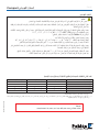
Märkeekt och strömförbrukning
Eekt Märkeekt
220–240V / 380–415V 50–60Hz
Strömförbrukning
230V, 1-fas 230V, 3-fas 400V, 3-fas
3 kW 2.7–3.5 kW 13A 8A 5A
6 kW 5.4–6.5 kW 26A 15A 9A
9 kW 8.1–9.7 kW —23A 14A
12 kW 10.8–13 kW — 31A 18A
15 kW 13.5–16.2 kW —38A 22A
18 kW 16.2–19.4 kW —46A 27A
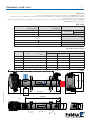
Dimensioner
Typskylt
Flödesvakt
Pressostat

5
SVENSKA
Elvärmare Kompakt
MA45-19 SE (Instruktionens originalspråk)
Drawing no: M10824-4
2022-05-25 ASA
Installation elvärmare Compact
+/-
VISE
10
9
8
7
6
5
4
33
2
1
VARNING
• Vatteninloppet på denna apparat får inte anslutas till inloppsvatten från något annat
värmesystem.
• Denna apparat skall ALLTID vara installerad minst 200 mm under normal vattennivå,
se installationsexempel.
• Ventiler får ej installeras så att vattenödet genom värmaren oavsiktligt kan stängs av.
• Installationen skall vara så utförd att värmaren inte kan självdräneras vid utebliven pool-
vattencirkulation och luftckor ej kan bildas.
• Värmaren skall installeras på returledningen till poolen EFTER ev lter.
• Ev. dosering av klor, syra eller liknande skall göras EFTER värmaren i ödesriktningen.
• Markering av ödesriktning på värmaren visar vilken anslutning som gäller för inlopp och
utlopp.
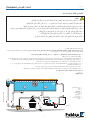
Bild 3
1. Bräddavlopp
2. Inlopp
3. Belysning
4. JetSwim
5. Bottenavlopp
6. Pump
7. Filter
8. Elvärmare
9. Backventil
10. Avlopp
Röranslutning utförs FÖRE elinstallation.
Elvärmaren skall monteras liggande med kopplingsdosan vänd uppåt (enligt ritning). Värmaren kan endast placeras
stående under förutsättning att den monteras så att vattnet i rören står minst 50 cm över värmaren.
• Anslutning skall göras med PVC-rör Ø50 mm med minst 200 mm rak längd före och efter värmaren.
(Rörens innerdiameter min. 42 mm.)
• Installera ej avstängningsventil mellan värmaren och poolen. Om ventil erfordras mellan poolen/badtunnan skall detta vara
en backventil.
• Installera gärna en nivåvakt på poolen/badtunnan så att värmaren automatiskt slår ifrån vid för låg vattennivå.
• Värmaren får ej övertäckas, ej placeras i närheten av brännbart material eller i direkt solsken.
• Om värmaren placeras mot brännbart material, skall en brandsäker skiva eller liknande placeras mellan värmaren och bränn-
bart material. Skivan skall täcka 10 cm utanför värmarens yttermått.
• Värmaren skall monteras i ett icke väderutsatt läge och vara skyddad mot vatteninträngning.
• Om placeringen av värmaren är sådan att frysrisk nns skall installationen vara så utförd att värmaren kan tömmas på allt
vatten.
Om installationsanvisningen inte följs gäller ej produktgarantin.
Installationsexempel:
Installation i cirkulationssystem

6
SVENSKA
Elvärmare Kompakt
MA45-19 SE (Instruktionens originalspråk)
Elinstallation
VARNING
• Den elektriska installationen får endast utföras av behörig elinstallatör enligt de instruktioner
som medföljer värmaren.
• Eftersom elinstallationsregler skiljer sig åt mellan olika länder behöver kontaktorer, kablar,
anslutningskomponenter och kapslingar väljas utifrån lokala regler.
• En huvudströmbrytare ska installeras före värmarens samtliga spänningsförande el-
anslutningar. Det skall vara en allpolig brytare som uppfyller kraven i IEC/EN 60335-1
stycke 7.12.2, 22.2 och 24,3.
• Pahlén rekommenderar installation av en jordfelsbrytare.
• Värmaren skall anslutas enligt kopplingsschema nedan.
• Styrspänningen kopplas: för 230V 1-fas och 400V 3-fas till L1 och N,
för 230V 3-fas till L1 och L2.
Observera att styrspänningen måste förses med en separat säkring på 5–10 Ampere för
de spänningsförande elanslutningarna.
• Värmaren skall installeras på ett sådant sätt att den inte kan aktiveras om inte cirkulations-
pumpen är i drift (tillräckligt öde), dvs manöverströmmen till värmarens kontaktor skall
styras över pumpents kontaktor.
• Spänninen till värmaren får ej variera mer än +5% till –10% i förhållande till modellens och
typskyltens specikation.
• Monteringsmetod skall väljas så att temperaturbegränsningen inte överskrids för någon
komponent vid full belastning.
Minikrav för kontaktorer (huvudbrytare) och kopplingsmaterial
Kopplingsalternativ 230V 1-fas 230V 3-fas 400V 3-fas
Brytarpoler 24 4
Spänning 240VAC 240VAC 415VAC
Eekt Enligt märkskylt* Enligt märkskylt* Enligt märkskylt*
Ström Enligt märkskylt* Enligt märkskylt* Enligt märkskylt*
Temperatur 60ºC** 60ºC** 60ºC**
* Se tabell “Märkeekt och strömförbrukning”
** Den temperatur komponenten får på installationsplatsen vid max tillåten omgivningstemperatur, men minst +45º och
maximalt eektuttag ur värmaren. Temperaturen beror på hur väl ventilerad installationen är.
OBS!
Monterade kablar är endast testkablar. Dessa får ej användas för inkoppling.

7
SVENSKA
Elvärmare Kompakt
MA45-19 SE (Instruktionens originalspråk)
Compact 220-240V 3-phase
C2
C1
L3
L2
L1
E10087-0
2020-10-08 ASA
A1A1 A2A2
L1
L2
L3
BU = Blue
RD = Red
WH = White
3 1
Compact
WH
WH
RD
RD
BU
BU
F1
M
L1
L2
L1
N
M
Compact 380-415V 3-phase
C2
C1
L3
L2
L1
E10092-0
2020-10-08 ASA
A1A1 A2A2
L1
L2
L3
BU = Blue
RD = Red
WH = White
31
RD
BU WH
RD
BU
WH
Compact
F1
M
N
L1
L1
N
M
Compact 220-240V 1-phase
C2
C1
L1
N
E10088-0
2020-10-08 ASA
A1A1 A2A2
L1
L2
L3
BU = Blue
RD = Red
WH = White
31
BU
BU WH
WH RD
RD
Compact
F1
M
N
L1
L1
N
M
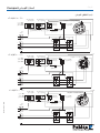
Elschema
380–415V 3~
BU = blå
RD = röd
WH
= vit
Överhettnings-
skydd
Pressostat pin 1 och 3
eller
Flödesvakt
Potentialfri kontakt
Utvändigt
motorskydd
3-fas
Termostat
Elpatron 3–18kW
Säkring
5–10A
Utvändigt
motorskydd
1-fas
220–240V 3~
BU = blå
RD = röd
WH
= vit
Överhettnings-
skydd
Pressostat pin 1 och 3
eller
Flödesvakt
Potentialfri kontakt
Utvändigt
motorskydd
3-fas
Termostat
Elpatron 3–18kW
Säkring
5–10A
Utvändigt
motorskydd
1-fas
220–240V 1~
BU = blå
RD = röd
WH
= vit
Överhettnings-
skydd
Pressostat pin 1 och 3
eller
Flödesvakt
Potentialfri kontakt
Utvändigt
motorskydd
3-fas
Termostat
Elpatron 3–6kW
Säkring
5–10A
Utvändigt
motorskydd
1-fas

8
SVENSKA
Elvärmare Kompakt
MA45-19 SE (Instruktionens originalspråk)
This document and its contents are the exclusive
property of Pahléns and may not be copied,
reproduced, transmitted or communicated to a third
party, or used for any purpose without written permission.
Art.no.
Rev.no.
Scale
Designed by: Approved by:
Revised by: Date
Drawn by: Date
Drawing number
Assembly drawing no.
Surface treatment
part of ISO 2768-1
The tolerance class in accordance with this
E
Box 728, SE-194 27 Upplands Väsby, Sweden
Phone +46 8 59411050, Fax +46 8 59086880
TS
139VXYZZ
TS 2007-12-12
ASA 2019-07-23
Medium
Elvärmare kompakt 3-18kW
M10931 3
A
B
Start
1. Fyll vatten i poolen till rätt nivå.
2. Starta pumpen till poolvattencirkulationen.
3. Kontrollera att vattnet cirkulerar normalt i anläggningen och att all luft töms ur systemet.
Värmaren skall vara helt vattenfylld innan strömmen slås på.
Först när all luft tömts ur systemet får värmaren slås på.
4. Funktionsprova värmaren genom att vrida termostatratten fram och tillbaka och kontrollera att termostatens kontaktor slår
till och från.
Flödesvakten kontrolleras genom att stänga av ödet genom värmaren med en avstängningsventil och kontrollera att
kontaktorerna slår ifrån. Sätt på vattnet igen. Kontaktorerna skall då slå på igen.
5. Ställ in önskad pooltemperatur med termostatvredet.
6. Vattnet värms nu upp till önskad temperatur.
Handhavande
Vid backspolning och rengöring av ltret skall strömmen till värmaren slås ifrån.
Vid frysrisk skall strömmen slås av och värmaren tömmas på allt vatten.
Allmän info
För att säkerställa god funktion och lång livslängd på värmaren är det viktigt att nedanstående rekommenderade värden
beträande vattenkvalitén följs.
Klorhalt: max 3,5 mg/l (ppm)
pH-värde: 7,2–7,6
Alkalinitet: 60–120 mg/l (ppm)
Kalciumhårdhet: 100–300 mg/l (ppm)
Järn: max 0,1 mg/l *
Koppar: max 0,2 mg/l *
Mangan: max 0,05 mg/l *
Fosfor: max 0,01 mg/l *
Nitrat: max 50 mg/l *
* Enligt EN 16713-3
Compact Compact Titan
Klorid(salt)halt: max 250 mg/l max 35000 mg/l
Om dessa gränsvärden för vattenkvalitén inte följs gäller ej produktgarantin.
Avfallshantering och återvinning
Du måste kassera denna produkt enligt lokala lagar och förordningar.
Eftersom denna produkt innehåller elektroniska komponenter måste den kasseras separat från hushållsavfall.
När den här produkten når slutet av sin livscykel, kontakta lokala myndigheter för att ta reda på mer om avfallshantering och
återvinning.
Felsökning:
1. Kontrollera säkringarna.
2. Kontrollera att systemet har erforderligt öde genom värmaren.
Kontrollera att eventuell ödesvakt är monterad så att pilen på ödesvakthuset överensstämmer med vattnets ödesriktning.
3. Eventuell pressostat är ej sluten:
Pressostaten är förinställd på 0,25 bar. Om inte rätt tryck uppnås, skall returledningen till poolen strypas något för att öka
mottrycketi returledningen.
4. Kontrollera om överhettningsskyddet har löst ut, undersök orsaken.
Efter att orsaken är klarlagd och åtgärdad återställs överhettnings-
skyddet genom att:
- Skruva bort skyddshuven (A).
- Tryck in återställningsknappen (B) på kopplingsboxen.
- Skruva tillbaka skyddhuven igen.
5. Kontrollera värmarens funktion, se punkt 4 under “Start”.
6. Ställ om termostaten till en högre temperatur.
7. Om problemet kvarstår: kontakta installatören.

9
ENGLISH
Compact electric heater
MA45-19 GB Translation of the original instructions (Swedish)
It is important to read through this manual carefully in order to ensure the function and useful life of the pool equipment.
This manual can also be found at www.pahlen.com .
Pahlén AB is not responsible for the product warranty or damage caused by incorrect installation, use or incorrect maintenance.:
WARNING
• This appliance must not be used to heat drinking water.
• This appliance must not be used in aggressive water, salt water or pools/hot tubs with a
chlorine machine/salt chlorinator, see the recommended water quality values.
• The water inlet on this appliance must not be connected to the water from any other water
heating system.
• The appliance must be installed in accordance with applicable national laws and provisions
and the electrical installation must only be carried out by a qualied electrician.
• Do not start installing the appliance until you have read and understood the installation
instructions and warnings in this manual. If you have any questions about the installation
instructions or warnings, please contact your local dealer.
• Under no circumstances may this appliance be started without being completely lled with
water.
• This appliance must not be covered, placed near combustible material or in direct sunlight.
• This appliance must not be used by very young children (0-3 years).
• This appliance must not be used by young children (3-8 years) and people with signicant
and complex disabilities unless they are under constant supervision by a person who is
responsible for their safety.
• This appliance may be used by children over 8 years of age and persons with reduced
physical, sensory or mental capabilities or lack of experience or knowledge, provided that
they’re under supervision or have received information on how to use the appliance safely
and understand risks that may occur by a person who is responsible for their safety.
• Children are not allowed to play with the appliance.
• This appliance should not be cleaned or maintained by children without supervision.
• Failure to follow the installation instructions invalidates the product warranty.

10
ENGLISH
Compact electric heater
MA45-19 GB Translation of the original instructions (Swedish)
A-A
D-D ( 1 : 2 )
Art.no.
Rev.no.
Scale
Designed by: Approved by:
Revised by: Date
Drawn by: Date
Drawing number
Assembly drawing no.
Surface treatment
part of ISO 2768-1
The tolerance class in accordance with this
E
Box 728, SE-194 27 Upplands Väsby, Sweden
Phone +46 8 59411050, Fax +46 8 59086880
1:2
13011T
OA 2013-04-10
TK 2016-10-07
Medium
Kompakt assembly short
Mantel elv komp-kort/flv
Titanium M11819 1
M11818
Titanium Gr 2Round nut ½"
17
M11817
Titanium Gr 2Round nut 2" Chamferd
16
M11816Titanium Gr 2Round nut 1½"1
5
M11815Titanium Gr 2
Rount nut 1½" Turning Ø
14
M11814
Titanium Gr 2Round nut 1/8"
13
M11813
Titanium Gr 2Gable kompakt
12
M11820
Titanium Gr 2
Kompakt body short11
Drawing.no:Art.noMaterialTitle/ NameQty.Item.
This document and its contents are the exclusive
property of Pahléns and may not be copied,
reproduced, transmitted or communicated to a third
party, or used for any purpose without written permission.
AA
D
1
6
4
3
5
2
313
14
54
10
7
9
All threads (G) according to: EN ISO 228-1
REVISION HISTORY
REV DESCRIPTION DATE APPROVED
1Dim 26 (+2/0) added. Dim 8.5 removed. 2016-10-07 TK
1
26 -0
2
+
1½"
69
A-A
A
A
123,5 329 (429)
39
148
97
69
1/2"
359259 ( )
1 ½"
39
2"
172
205
Compact
139VXYZZ after 2019
M10931-6
Dimensions 3-6kW (in brackets 9-18kW)
Compact Compact T
Product description
The compact electric heater is available from 3 kW to 18 kW, see the type plate on the product.
The heater element is controlled by the analogue thermostat. Built-in safety devices in the heater are a ow monitor or pressostat
and a thermostat and manually resettable overheating protection.
NOTE! The standard version of the heater is not intended for use in aggressive water, salt water or in pools with a chlorine
machine/salt generator. In such contexts, the Compact Titanium Electric Heater is required.
Technical data
Compact
with ow switch
Compact
with pressostat
Minimum ow 3–9kW: 90 l/min 20 l/min
12–18kW: 90 l/min 40 l/min
Maximum ow: 300 l/min 300 l/min
Voltage: 230 V 1-phase (3-6 kW), 230 V 3-phase (3-18 kW), 400 V 3-phase
(3-18 kW)
Maximum pressure: 2,5 bar (2,5 Pa) 4 bar (4 Pa)
Maximum temperature: 45°C 45°C
Enclosure class: IP44
Rated power and power consumption
Power Rated power
220–240V / 380–415V 50-60Hz
Power consumption
230V, 1-phase 230V, 3-phase 400V, 3-phase
3 kW 2.7–3.5 kW 13A 8A 5A
6 kW 5.4–6.5 kW 26A 15A 9A
9 kW 8.1–9.7 kW —23A 14A
12 kW 10.8–13 kW — 31A 18A
15 kW 13.5–16.2 kW —38A 22A
18 kW 16.2–19.4 kW —46A 27A
Dimensions
Type plate
Flow monitor
Pressostat

11
ENGLISH
Compact electric heater
MA45-19 GB Translation of the original instructions (Swedish)
Drawing no: M10824-4
2022-05-25 ASA
Installation elvärmare Compact
+/-
VISE
10
9
8
7
6
5
4
33
2
1
Picture 3
1. Skimmer
2. Inlet
3. Lighting
4. JetSwim
5. Bottom drain
6. Pump
7. Filter
8. Electric heater
9. Non-return valve
10. Drain
WARNING
• The water inlet on this appliance must not be connected to the inlet water from any other
heating system.
• This appliance must ALWAYS be installed at least 200 mm below the normal water level,
see the installation example.
• Valves must not be installed so that the ow of water through the heater can be uninten-
tionally turned o.
• The installation must be carried out in such a way that the heater cannot be self-drained in
the absence of pool water circulation and air pockets cannot be formed.
• The heater must be installed on the return line to the pool AFTER a possible lter.
• If necessary, chlorine, acid or similar should be dosed after the heater in the direction of
ow.
• The ow direction marking on the heater indicates the connections that apply for the inlet
and outlet.
Pipe connections are made BEFORE electrical installation.
The electric heater must be mounted horizontally with the junction box facing upwards (as shown on the drawing).
The heater can only be placed vertically if it is installed so that the water in the pipes is at least 50 cm above the heater.
• Connections must be made using PVC pipe Ø50 mm with at least 200 mm of straight length before and after the
heater.
(Inner diameter of pipes min. 42 mm.)
• Do not install the shut-o valve between the heater and the pool. If a valve is required between the pool/hot tub, this must be
a non-return valve.
• Ideally install a level monitor on the pool/hot tub so that the heater automatically switches o at too low a water level.
• The heater must not be covered, placed close to combustible material or in direct sunlight.
• If the heater is placed against combustible material, a reproof board or the like must be placed between the heater and
combustible material. The board must cover 10 cm outside the heater’s outer dimensions.
• The heater must not be installed in a position that is exposed to the elements and must be protected against the ingress of
water.
• If the position of the heater is such that there is a risk of freezing, the installation must be carried out in such a way that the
heater can be drained of all water.
Failure to follow the installation instructions invalidates the product warranty.
Installation example
Installation in circulation system

12
ENGLISH
Compact electric heater
MA45-19 GB Translation of the original instructions (Swedish)
Electrical installation
WARNING
• The electrical installation may only be carried out by a qualied electrician in accordance
with the instructions provided with the heater.
• As electrical installation regulations dier from country to country, contactors, cables,
connection components, and enclosures must be selected based on local regulations.
• A main isolator must be installed before all live electrical connections on the heater.
This must be an all-pole isolator that satises the requirements set out in IEC/EN 60335-1
paragraphs 7.12.2, 22.2 and 24.3.
• Pahlén recommends the installation of a residual current device.
• The heater must be connected according to the wiring diagram below.
• The control voltage is connected: for 230 V 1-phase and 400 V 3-phase to L1 and N,
for 230 V 3-phase to L1 and L2.
Note that the control voltage must be tted with a separate fuse of 5-10 amps for the live
electrical connections.
• The heater must be installed in such a way that it cannot be activated unless the circulation
pump is in operation (sucient ow), i.e. the control current to the heater’s contactors must
be controlled over the pump’s contactors.
• The voltage to the heater must not uctuate more than +5% to –10% in relation to the
specication of the model and type plate.
• The installation method must be chosen in such a way that the temperature limit is not
exceeded for any component at full load.
Minimum requirements for contactors (main isolator) and coupling material
Connection options 230 V, 1-phase 230 V, 3-phase 400 V, 3-phase
Isolator poles 24 4
Voltage 240 VAC 240 VAC -415 VAC
Power According to the rating
plate*
According to the rating
plate*
According to the rating
plate*
Current According to the rating
plate*
According to the rating
plate*
According to the rating
plate*
Temperature 60ºC** 60ºC** 60ºC**
* See the table “Rated power and power consumption”
** The temperature the component receives at the installation site at the maximum ambient temperature, but at least +45º and
the maximum power output from the heater. The temperature depends on how well ventilated the installation is.
NOTE!
Installed cables are only test cables. These must not be used for connection.

13
ENGLISH
Compact electric heater
MA45-19 GB Translation of the original instructions (Swedish)
Compact 220-240V 3-phase
C2
C1
L3
L2
L1
E10087-0
2020-10-08 ASA
A1A1 A2A2
L1
L2
L3
BU = Blue
RD = Red
WH = White
3 1
Compact
WH
WH
RD
RD
BU
BU
F1
M
L1
L2
L1
N
M
Compact 380-415V 3-phase
C2
C1
L3
L2
L1
E10092-0
2020-10-08 ASA
A1A1 A2A2
L1
L2
L3
BU = Blue
RD = Red
WH = White
31
RD
BU WH
RD
BU
WH
Compact
F1
M
N
L1
L1
N
M
Compact 220-240V 1-phase
C2
C1
L1
N
E10088-0
2020-10-08 ASA
A1A1 A2A2
L1
L2
L3
BU = Blue
RD = Red
WH = White
31
BU
BU WH
WH RD
RD
Compact
F1
M
N
L1
L1
N
M
Wiring diagram
380–415 V 3~
BU = blue
RD = red
WH
= white
Overheating
protection
Pressostat pin 1 and 3
or Flow guard
Potential-free contact
External
motor protection
3-phase
Thermostat
Heater element
3-18 kW
Fuse
5–10 A
External
motor protection
1-phase
220-240 V 3~
BU = blue
RD = red
WH
= white
Overheating
protection
Pressostat pin 1 and 3
or Flow guard
Potential-free contact
External
motor protection
3-phase
Thermostat
Heater element 3-18 kW
Fuse
5–10 A
External
motor protection
1-phase
220-240 V 1~
BU = blue
RD = red
WH
= white
Overheating
protection
Pressostat pin 1 and 3
or Flow guard
Potential-free contact
External
motor protection
3-phase
Thermostat
Heater element
3-6 kW
Fuse
5–10 A
External
motor protection
1-phase

14
ENGLISH
Compact electric heater
MA45-19 GB Translation of the original instructions (Swedish)
This document and its contents are the exclusive
property of Pahléns and may not be copied,
reproduced, transmitted or communicated to a third
party, or used for any purpose without written permission.
Art.no.
Rev.no.
Scale
Designed by: Approved by:
Revised by: Date
Drawn by: Date
Drawing number
Assembly drawing no.
Surface treatment
part of ISO 2768-1
The tolerance class in accordance with this
E
Box 728, SE-194 27 Upplands Väsby, Sweden
Phone +46 8 59411050, Fax +46 8 59086880
TS
139VXYZZ
TS 2007-12-12
ASA 2019-07-23
Medium
Elvärmare kompakt 3-18kW
M10931 3
A
B
Start
1. Fill the pool with water to the right level.
2. Start the pump for pool water circulation.
3. Check that the water circulates as normal in the system and that all air is vented from the system.
The heater must be completely water-lled before switching on the power.
Only when all air has been vented from the system can the heater be switched on.
4. Functional test the heater by turning the thermostat knob back and forth and check that the thermostat contactor switches
and releases.
The ow monitor is checked by turning o the ow through the heater with a shut-o valve and check that the contactors
release. Turn on the water again. The contactors should then switch on again.
5. Set the desired pool temperature with the thermostat knob.
6. The water is now heated to the desired temperature.
Operation
When backwashing and cleaning the lter, switch o the power to the heater.
In the event of a risk of freezing, the power must be switched o and the heater drained of all water.
General info
In order to ensure good operation and a long heater life, it is important that the following recommended values regarding water
quality are followed.
Chlorine content: max 3.5 mg/l (ppm)
pH-value: 7.2–7.6
Alkalinity: 60–120 mg/l (ppm)
Calcium hardness: 100–300 mg/l (ppm)
Iron: max 0.1 mg/l *
Copper: max 0.2 mg/l *
Manganese: max 0.05 mg/l *
Phosphorus: max 0.01 mg/l *
Nitrate: max 50 mg/l *
* According to EN 16713-3
Compact Compact Titanium
Chloride (salt) content: max 250 mg/l max 35,000 mg/l
Failure to follow the limit values for water quality invalidates the product warranty.
Disposal and recycling
You must dispose of this product in accordance with local laws and provisions.
Since this product contains electronic components, it must be disposed of separately from household waste.
When this product reaches the end of its life cycle, contact your local authorities to nd out more about disposal and recycling.
Troubleshooting:
1. Check the fuses.
2. Check that the system has the requisite ow through the heater.
Check that a possible ow monitor is tted so that the arrow on the ow monitor housing corresponds to the ow direction of
the water.
3. The pressostat, if tted, is not closed:
The pressostat is preset to 0.25 bar. If the correct pressure is not reached, the return line to the pool should be throttled
slightly to increase the counter-pressure in the return line.
4. Check whether the overheating protection has tripped, investigate the cause.
After the cause has been established and rectied, the overheating
protection is reset by:
- Unscrewing the protective cap (A).
- Press in the reset button (B) on the junction box.
- Ret the protective cap again.
5. Check the operation of the heater, see point 4 under “Start”.
6. Reset the thermostat to a higher temperature.
7. If the problem persists: contact the installer.

15
DEUTSCH
Elektroheizer Compact
MA45-19 DE Übersetzung der ursprünglichen Anweisungen (Schwedisch)
Es ist wichtig, diese Bedienungsanleitung sorgfältig zu lesen, um die Funktion und Lebensdauer der Poolausrüstung zu
gewährleisten.
Diese Bedienungsanleitung steht unter www.pahlen.com als Download zur Verfügung.
Pahlén AB ist nicht verantwortlich für Produktgewährleistung oder für Schäden, die durch unsachgemäße Installation,
Handhabungsfehler oder mangelnde Wartung entstehen.
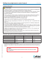
WARNHINWEIS
• Dieses Gerät darf nicht zum Erhitzen von Trinkwasser verwendet werden.
• Dieses Gerät darf nicht in aggressivem Wasser, Salzwasser oder Pools/Badefässern mit
Chlorgenerator/Salzelektrolysegerät verwendet werden, siehe empfohlene Werte zur
Wasserqualität.
• Der Wasserzulauf dieses Geräts darf nicht an Wasser aus einem anderen Wasserheiz-
system angeschlossen werden.
• Das Gerät muss in Übereinstimmung mit den geltenden nationalen Gesetzen und
Vorschriften installiert werden. Die elektrische Installation darf nur von einem qualizierten
Elektriker durchgeführt werden.
• Beginnen Sie erst mit der Installation des Geräts, wenn Sie die Installationsanweisungen
und Warnhinweise in dieser Anleitung gelesen und verstanden haben. Wenn Sie Fragen
zu Installationsanweisungen oder Warnhinweisen haben, wenden Sie sich bitte an Ihren
Händler vor Ort.
• Dieses Gerät darf unter keinen Umständen in Betrieb genommen werden, ohne dass es
vollständig mit Wasser gefüllt ist.
• Dieses Gerät darf nicht abgedeckt, in der Nähe von brennbaren Materialien oder in
direktem Sonnenlicht aufgestellt werden.
• Dieses Gerät darf nicht von sehr kleinen Kindern (0–3 Jahre) verwendet werden.
• Dieses Gerät darf nicht von Kleinkindern (3-8 Jahre) und Menschen mit sehr umfang-
reichen und komplexen Behinderungen benutzt werden, es sei denn, sie werden ständig
von einer für ihre Sicherheit verantwortlichen Person beaufsichtigt.
• Dieses Gerät kann von Kindern ab 8 Jahren und älter sowie Personen mit eingeschränk-
ten körperlichen oder geistigen Fähigkeiten oder eingeschränkten Sinnesfähigkeiten oder
mangelnder Erfahrung und Wissen benutzt werden, wenn sie unter Aufsicht stehen oder
Anweisungen zu einem sicheren Gebrauch erhalten haben und die mit dem Gerät ver-
bundenen Gefahren verstehen.
• Kinder dürfen nicht mit dem Gerät spielen.
• Dieses Gerät darf von Kindern, die unbeaufsichtigt sind, gereinigt oder gewartet werden.
• Bei Nichtbeachtung der Installationsanweisungen verliert die Produktgarantie ihre
Gültigkeit.

16
DEUTSCH
Elektroheizer Compact
MA45-19 DE Übersetzung der ursprünglichen Anweisungen (Schwedisch)
A-A
D-D ( 1 : 2 )
Art.no.
Rev.no.
Scale
Designed by: Approved by:
Revised by: Date
Drawn by: Date
Drawing number
Assembly drawing no.
Surface treatment
part of ISO 2768-1
The tolerance class in accordance with this
E
Box 728, SE-194 27 Upplands Väsby, Sweden
Phone +46 8 59411050, Fax +46 8 59086880
1:2
13011T
OA 2013-04-10
TK 2016-10-07
Medium
Kompakt assembly short
Mantel elv komp-kort/flv
Titanium M11819 1
M11818
Titanium Gr 2Round nut ½"
17
M11817
Titanium Gr 2Round nut 2" Chamferd
16
M11816Titanium Gr 2Round nut 1½"1
5
M11815Titanium Gr 2
Rount nut 1½" Turning Ø
14
M11814
Titanium Gr 2Round nut 1/8"
13
M11813
Titanium Gr 2Gable kompakt
12
M11820
Titanium Gr 2
Kompakt body short11
Drawing.no:Art.noMaterialTitle/ NameQty.Item.
This document and its contents are the exclusive
property of Pahléns and may not be copied,
reproduced, transmitted or communicated to a third
party, or used for any purpose without written permission.
AA
D
1
6
4
3
5
2
313
14
54
10
7
9
All threads (G) according to: EN ISO 228-1
REVISION HISTORY
REV DESCRIPTION DATE APPROVED
1Dim 26 (+2/0) added. Dim 8.5 removed. 2016-10-07 TK
1
26 -0
2
+
1½"
69
A-A
A
A
123,5 329 (429)
39
148
97
69
1/2"
359259 ( )
1 ½"
39
2"
172
205
Compact
139VXYZZ after 2019
M10931-6
Dimensions 3-6kW (in brackets 9-18kW)
Compact Compact T
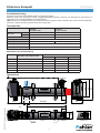
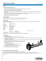
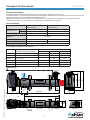
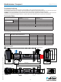
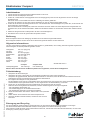
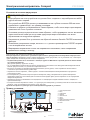
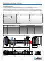
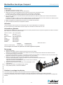
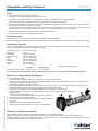
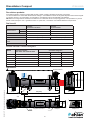
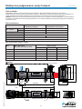
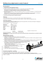
Produktbeschreibung
Der Elektroheizer Compact ist von 3 kW bis 18 kW erhältlich, siehe Typenschild auf dem Produkt.
Die Heizstäbe werden über den analogen Thermostat gesteuert. Eingebaute Sicherheitsvorrichtungen im Heizer sind ein Durch-
usswächter bzw. ein Druckregler und ein Thermostat sowie ein manuell rückstellbarer Überhitzungsschutz.
HINWEIS! In der Standardausführung ist der Heizer nicht für den Einsatz in aggressivem Wasser, Salzwasser oder in Pools mit
Chlorgenerator/Salzelektrolysegerät bestimmt. In diesem Fall ist der elektrische Heizer Compact Titan erforderlich.
Technische Daten
Compact
mit Durchusswächter
Compact
mit Druckregler
Mindestdurch-
uss
3–9 kW: 90 l/min 20 l/min
12–18 kW: 90 l/min 40 l/min
Max. Durchuss: 300 l/min 300 l/min
Spannung: 230 V 1-phasig (3–6 kW), 230 V 3-phasig (3–18 kW), 400 V 3-phasig (3–18 kW)
Höchstdruck: 2,5 bar (2,5 Pa) 4 bar (4 Pa)
Max. Betriebstemperatur: 45 °C
Dichtigkeitsklasse: IP44
Nennleistung und Stromverbrauch
Leistung Nennleistung
220–240 V / 380–415 V 50–60 Hz
Stromverbrauch
230 V, 1-phasig 230 V, 3-phasig 400 V, 3-phasig
3 kW 2,7–3,5 kW 13 A 8 A 5 A
6 kW 5,4–6,5 kW 26 A 15 A 9 A
9 kW 8,1–9,7 kW —23 A 14 A
12 kW 10,8–13 kW —31 A 18 A
15 kW 13,5–16.2 kW —38 A 22 A
18 kW 16,2–19.4 kW —46 A 27 A
Abmessungen
Typenschild
Durchusswächter
Druckregler

17
DEUTSCH
Elektroheizer Compact
MA45-19 DE Übersetzung der ursprünglichen Anweisungen (Schwedisch)
Drawing no: M10824-4
2022-05-25 ASA
Installation elvärmare Compact
+/-
VISE
10
9
8
7
6
5
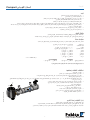
4
33
2
1
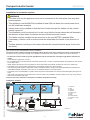
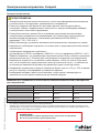
WARNHINWEIS
• Der Wasserzulauf dieses Geräts darf nicht an Einspritzwasser aus einem anderen Heiz-
system angeschlossen werden.
• Dieses Gerät muss IMMER mindestens 200 mm unter dem normalen Wasserstand installiert
werden, siehe Installationsbeispiel.
• Die Ventile dürfen nicht so installiert werden, dass der Wasseruss durch den Heizer
versehentlich abgeschaltet werden kann.
• Die Anlage muss so ausgelegt sein, dass sich das Heizgerät bei fehlender Poolwasserzirku-
lation nicht selbst entleeren kann und sich keine Lufteinschlüsse bilden können.
• Der Heizer muss an der Rücklaueitung zum Pool NACH einem Filter installiert werden.
• Jegliche Dosierung von Chlor, Säure oder Ähnlichem muss NACH dem Heizer in Durch-
ussrichtung erfolgen.
• Die Markierung der Durchussrichtung auf dem Heizer zeigt an, welcher Anschluss für den
Ein- und Auslass vorgesehen ist.
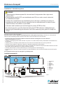
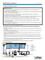
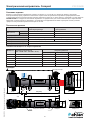
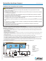
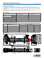
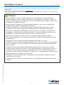
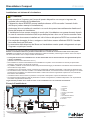
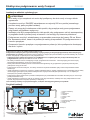
Abbildung 3
1. Überlauf
2. Einlass
3. Beleuchtung
4. JetSwim
5. Bodenauslass
6. Pumpe
7. Filter
8. Elektroheizer
9. Rückschlagventil
10. Abuss
Das Anschließen der Rohre erfolgt vor der elektrischen Installation.
Der Elektroheizer ist liegend, mit der Anschlussdose nach oben gerichtet, zusammenzubauen (wie abgebildet).
Der Heizer kann nur dann aufrecht aufgestellt werden, wenn er so montiert ist, dass das Wasser in den Rohren mindestens
50 cm über dem Heizer steht.
• Der Anschluss erfolgt mit PVC-Rohren mit Ø 50 mm und einer geraden Länge von mindestens 200 mm vor und nach
dem Heizer.
(Innendurchmesser der Rohre min. 42 mm.)
• Das Absperrventil darf nicht zwischen Heizer und Pool installiert werden. Falls ein Ventil zwischen Pool/Badefass erforderlich
ist, muss ein Rückschlagventil verwendet werden.
• Installieren Sie gegebenenfalls eine Füllstandsüberwachung am Pool/Badefass, sodass sich der Heizer bei zu geringem
Wasserstand automatisch abschaltet.
• Der Heizer darf nicht abgedeckt, nicht in der Nähe von brennbarem Material oder in direkter Sonneneinstrahlung platziert
werden.
• Wenn der Heizer an brennbarem Material aufgestellt wird, muss eine feuerfeste Scheibe oder Ähnliches zwischen Heizer
und brennbarem Material angebracht werden. Die Scheibe sollte 10 cm über die Außenabmessungen des Heizgeräts hinaus-
reichen.
• Der Heizer ist an einer nicht dem Wetter ausgesetzten Stelle zu installieren und gegen das Eindringen von Wasser zu schützen.
• Ist der Standort des Heizgerätes so gewählt, dass die Gefahr des Einfrierens besteht, muss die Installation so durchgeführt
werden, dass das Heizgerät vollständig entleert werden kann.
Bei Nichtbeachtung der Installationsanweisungen verliert die Produktgarantie ihre Gültigkeit.
Installationsbeispiel:
Installation im Kreislaufsystem

18
DEUTSCH
Elektroheizer Compact
MA45-19 DE Übersetzung der ursprünglichen Anweisungen (Schwedisch)
Elektrische Installation
WARNHINWEIS
• Die elektrische Installation darf nur von einem qualizierten Elektriker gemäß den mit dem
Heizer gelieferten Anleitungen durchgeführt werden.
• Da sich die Vorschriften für die Elektroinstallation zwischen den Ländern unterscheiden,
müssen Schütze, Kabel, Anschlussbauteile und Gehäuse auf der Grundlage der landes-
spezischen Vorschriften ausgewählt werden.
• Vor allen spannungsführenden elektrischen Anschlüssen des Heizers muss ein Haupt-
schalter installiert werden. Es muss ein allpoliger Schalter sein, der die Anforderungen der
IEC/EN 60335-1 Absätze 7.12.2, 22.2 und 24.3 erfüllt.
• Pahlén empehlt die Installation eines Fehlerstromschutzschalters.
• Der Heizer ist gemäß nachstehendem Schaltplan anzuschließen.
• Die Steuerspannung wird angeschlossen:
für 230 V 1-phasig und 400 V 3-phasig an L1 und N, für 230 V 3-phasig an L1 und L2.
Beachten Sie, dass die Steuerspannung mit einer separaten Sicherung von 5-10 Ampere
für die stromführenden elektrischen Anschlüsse ausgestattet sein muss.
• Der Heizer muss so installiert werden, dass er nur aktiviert werden kann, wenn die Umwälz-
pumpe in Betrieb ist (ausreichender Durchuss), d. h. der Betriebsstrom zum Schütz des
Heizgeräts muss über das Pumpenschütz gesteuert werden.
• Die Spannung des Heizers darf nicht mehr als + 5 % bis -10 % gegenüber der Modell- und
Typenschildspezikation abweichen.
• Das Montageverfahren muss so gewählt werden, dass die Temperaturgrenze für kein
Bauteil bei voller Belastung überschritten wird.
Mindestanforderungen für Schütze (Hauptschalter) und Anschlussmaterial
Anschlussmöglichkeiten 230 V 1-phasig 230 V 3-phasig 400 V 3-phasig
Schalterpole 24 4
Spannung 240 VAC 240 VAC 415 VAC
Leistung Gemäß Typenschild* Gemäß Typenschild* Gemäß Typenschild*
Strom Gemäß Typenschild* Gemäß Typenschild* Gemäß Typenschild*
Temperatur 60 ºC** 60 ºC** 60 ºC**
* Siehe Tabelle „Nennleistung und Stromverbrauch“
** Die Temperatur, die das Bauteil am Installationsort bei der maximal zulässigen Umgebungstemperatur, jedoch mindestens
+45º und maximaler Leistungsabgabe der Heizung erhält. Die Temperatur hängt davon ab, wie gut die Anlage belüftet ist.
HINWEIS!
Die montierten Kabel sind nur Prüfkabel. Diese dürfen nicht zum Anschließen verwendet werden.

19
DEUTSCH
Elektroheizer Compact
MA45-19 DE Übersetzung der ursprünglichen Anweisungen (Schwedisch)
Compact 220-240V 3-phase
C2
C1
L3
L2
L1
E10087-0
2020-10-08 ASA
A1A1 A2A2
L1
L2
L3
BU = Blue
RD = Red
WH = White
3 1
Compact
WH
WH
RD
RD
BU
BU
F1
M
L1
L2
L1
N
M
Compact 380-415V 3-phase
C2
C1
L3
L2
L1
E10092-0
2020-10-08 ASA
A1A1 A2A2
L1
L2
L3
BU = Blue
RD = Red
WH = White
31
RD
BU WH
RD
BU
WH
Compact
F1
M
N
L1
L1
N
M
Compact 220-240V 1-phase
C2
C1
L1
N
E10088-0
2020-10-08 ASA
A1A1 A2A2
L1
L2
L3
BU = Blue
RD = Red
WH = White
31
BU
BU WH
WH RD
RD
Compact
F1
M
N
L1
L1
N
M
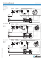
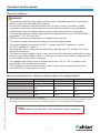
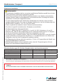
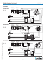
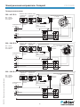
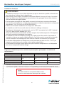
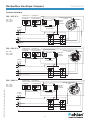
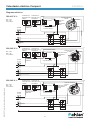
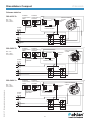
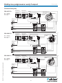
Schaltplan
380–415 V 3~
BU = blau
RD = rot
WH
= weiß
Überhitzungs-
schutz
Druckregler Stift 1 und 3
oder Durchusswächter
Potenzialfreier Kontakt
Externer
Motorschutz
3-phasig
Thermostat
Heizstab 3–18 kW
Sicherung
5–10 A
Externer
Motorschutz
1-phasig
220–240 V 3~
BU = blau
RD = rot
WH
= weiß
Überhitzungs-
schutz
Druckregler Stift 1 und 3
oder Durchusswächter
Potenzialfreier Kontakt
Externer
Motorschutz
3-phasig
Thermostat
Heizstab 3–18 kW
Sicherung
5–10 A
Externer
Motorschutz
1-phasig
220–240 V 1~
BU = blau
RD = rot
WH
= weiß
Überhitzungs-
schutz
Druckregler Stift 1 und 3
oder Durchusswächter
Potenzialfreier Kontakt
Externer
Motorschutz
3-phasig
Thermostat
Heizstab 3–6 kW
Sicherung
5–10 A
Externer
Motorschutz
1-phasig

20
DEUTSCH
Elektroheizer Compact
MA45-19 DE Übersetzung der ursprünglichen Anweisungen (Schwedisch)
This document and its contents are the exclusive
property of Pahléns and may not be copied,
reproduced, transmitted or communicated to a third
party, or used for any purpose without written permission.
Art.no.
Rev.no.
Scale
Designed by: Approved by:
Revised by: Date
Drawn by: Date
Drawing number
Assembly drawing no.
Surface treatment
part of ISO 2768-1
The tolerance class in accordance with this
E
Box 728, SE-194 27 Upplands Väsby, Sweden
Phone +46 8 59411050, Fax +46 8 59086880
TS
139VXYZZ
TS 2007-12-12
ASA 2019-07-23
Medium
Elvärmare kompakt 3-18kW
M10931 3
A
B
Inbetriebnahme
1. Lassen Sie bis zum entsprechenden Füllstand Wasser in den Pool.
2. Starten Sie die Umwälzpumpe des Pools.
3. Prüfen Sie, ob das Wasser ordnungsgemäß durch die Anlage gepumpt wird und ob die gesamte Luft aus der Anlage
abgelassen wird.
Der Heizer muss vor Einschalten des Stroms vollständig mit Wasser gefüllt sein.
Erst wenn die gesamte Luft aus dem System abgelassen ist, darf der Heizer eingeschaltet werden.
4. Prüfen Sie die Funktion des Heizgeräts durch Hin- und Herdrehen des Thermostatreglers und prüfen Sie, ob das Schütz des
Thermostats ein- und ausschaltet.
Der Durchusswächter wird überprüft, indem der Durchuss durch den Heizer mit einem Absperrventil ausgeschaltet und
kontrolliert wird, ob die Schütze abschalten. Stellen Sie das Wasser wieder an. Die Schütze müssen dann wieder einschal-
ten.
5. Stellen Sie die gewünschte Pooltemperatur mit dem Thermostatregler ein.
6. Das Wasser wird nun auf die gewünschte Temperatur erwärmt.
Bedienung
Beim Rückspülen oder bei der Reinigung des Filters muss der Heizer ausgeschaltet werden.
Bei Frostgefahr schalten Sie den Strom ab und lassen das gesamte Wasser aus dem Heizer ab.
Allgemeine Informationen
Um eine gute Funktion und lange Lebensdauer des Heizers zu gewährleisten, ist es wichtig, dass die folgenden empfohlenen
Werte bezüglich der Wasserqualität eingehalten werden.
Chlorgehalt: max. 3,5 mg/l (ppm)
pH-Wert: 7,2–7,6
Alkalinität: 60–120 mg/l (ppm)
Kalziumhärte: 100–300 mg/l (ppm)
Eisen: max. 0,1 mg/l *
Kupfer: max. 0,2 mg/l *
Mangan: max. 0,05 mg/l *
Phosphor: max. 0,01 mg/l *
Nitrat: max. 50 mg/l *
* Gemäß EN 16713-3
Compact Compact Titan
Chlorid(salz)gehalt: max. 250 mg/l max. 35000 mg/l
Werden diese Grenzwerte für die Wasserqualität nicht eingehalten, erlischt die Produktgarantie.
Entsorgung und Recycling
Sie sind verpichtet, dieses Produkt in Übereinstimmung mit den örtlichen Gesetzen und Vorschriften zu entsorgen.
Da dieses Produkt elektronische Bauteile enthält, muss es getrennt vom Hausmüll entsorgt werden.
Wenn dieses Produkt das Ende seines Lebensdauer erreicht hat, wenden Sie sich an die örtlichen Behörden, um mehr über
Entsorgung und Recycling zu erfahren.
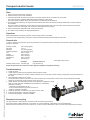
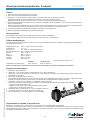
Fehlerbehebung:
1. Überprüfen Sie die Sicherungen.
2. Überprüfen Sie, dass in der Anlage ein erforderlicher Durchuss durch den Heizer gegeben ist.
Überprüfen Sie gegebenenfalls, dass der Durchusswächter so montiert ist, dass der Pfeil auf dem Gehäuse des Durch-
usswächters mit der Durchussrichtung des Wassers übereinstimmt.
3. Ein möglicher Druckregler ist nicht geschlossen:
Der Druckregler ist auf 0,25 bar voreingestellt. Wenn der richtige Druck nicht erreicht wird, muss die Rücklaueitung zum
Schwimmbecken leicht gedrosselt werden, um den Gegendruck in der Rücklaueitung zu erhöhen.
4. Prüfen Sie, ob der Überhitzungsschutz ausgelöst hat und untersuchen Sie die Ursache.
Nachdem die Ursache geklärt und behoben ist, wird der Überhitzungsschutz wie folgt rückgestellt:
- die Schutzkappe abschrauben (A).
- Den Resetknopf (B) an der Anschlussdose drücken.
- Die Schutzkappe aufsetzen und wieder anschrauben.
5. Prüfen Sie die Funktion des Heizers, siehe Punkt 4 unter „Inbetrieb-
nahme“.
6. Stellen Sie den Thermostat auf eine höhere Temperatur ein.
7. Wenn das Problem weiterhin besteht, wenden Sie sich an einen
Fachmann.
Seite wird geladen ...
Seite wird geladen ...
Seite wird geladen ...
Seite wird geladen ...
Seite wird geladen ...
Seite wird geladen ...
Seite wird geladen ...
Seite wird geladen ...
Seite wird geladen ...
Seite wird geladen ...
Seite wird geladen ...
Seite wird geladen ...
Seite wird geladen ...
Seite wird geladen ...
Seite wird geladen ...
Seite wird geladen ...
Seite wird geladen ...
Seite wird geladen ...
Seite wird geladen ...
Seite wird geladen ...
Seite wird geladen ...
Seite wird geladen ...
Seite wird geladen ...
Seite wird geladen ...
Seite wird geladen ...
Seite wird geladen ...
Seite wird geladen ...
Seite wird geladen ...
Seite wird geladen ...
Seite wird geladen ...
Seite wird geladen ...
Seite wird geladen ...
Seite wird geladen ...
Seite wird geladen ...
Seite wird geladen ...
Seite wird geladen ...
-
 1
1
-
 2
2
-
 3
3
-
 4
4
-
 5
5
-
 6
6
-
 7
7
-
 8
8
-
 9
9
-
 10
10
-
 11
11
-
 12
12
-
 13
13
-
 14
14
-
 15
15
-
 16
16
-
 17
17
-
 18
18
-
 19
19
-
 20
20
-
 21
21
-
 22
22
-
 23
23
-
 24
24
-
 25
25
-
 26
26
-
 27
27
-
 28
28
-
 29
29
-
 30
30
-
 31
31
-
 32
32
-
 33
33
-
 34
34
-
 35
35
-
 36
36
-
 37
37
-
 38
38
-
 39
39
-
 40
40
-
 41
41
-
 42
42
-
 43
43
-
 44
44
-
 45
45
-
 46
46
-
 47
47
-
 48
48
-
 49
49
-
 50
50
-
 51
51
-
 52
52
-
 53
53
-
 54
54
-
 55
55
-
 56
56


Pahlen MA45-19 Bedienungsanleitung
- Kategorie
- Raumheizungen
- Typ
- Bedienungsanleitung
- Dieses Handbuch eignet sich auch für
in anderen Sprachen
- français: Pahlen MA45-19 Le manuel du propriétaire
- italiano: Pahlen MA45-19 Manuale del proprietario
- polski: Pahlen MA45-19 Instrukcja obsługi
Verwandte Artikel
-
Pahlen MA45-01 Bedienungsanleitung
-
-
-
-
-
-
-
-
-
