
Mounting Instructions | Montageanleitung |
Notice de montage
English Deutsch Français
C16i

Hottinger Baldwin Messtechnik GmbH
Im Tiefen See 45
D-64239 Darmstadt
Tel. +49 6151 803-0
Fax +49 6151 803-9100
www.hbm.com
Mat.: 7-2002.5027
DVS: A1461-2.0 HBM: public
03.2017
E Hottinger Baldwin Messtechnik GmbH.
Subject to modifications.
All product descriptions are for general information only.
They are not to be understood as a guarantee of quality or
durability.
Änderungen vorbehalten.
Alle Angaben beschreiben unsere Produkte in allgemeiner
Form. Sie stellen keine Beschaffenheits- oder Haltbarkeits
garantie dar.
Sous réserve de modifications.
Les caractéristiques indiquées ne décrivent nos produits
que sous une forme générale. Elles n'impliquent aucune
garantie de qualité ou de durabilité.

Mounting Instructions | Montageanleitung |
Notice de montage
English Deutsch Français
C16i

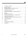
2 A1461-2.0 HBM: public C16i
English
1 Safety instructions 3........................................
2 Markings used 6............................................
2.1 The markings used in this document 6..........................
2.2 Symbols on the product 7.....................................
3 Scope of supply 8..........................................
3.1 Mounting accessories (optional) 8..............................
4 Mounting 9.................................................
4.1 Mounting procedure 12........................................
4.2 Procedure for special mounting situations 15.....................
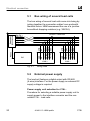
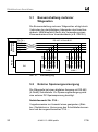
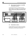
5 Electrical connection 19......................................
5.1 Bus wiring of several load cells 20...............................
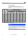
5.2 External power supply 20......................................
5.3 Command set C16i... 23.......................................
6 Options 24..................................................
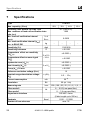
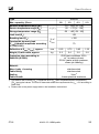
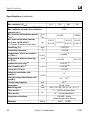
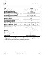
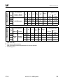
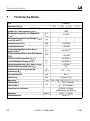
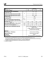
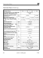
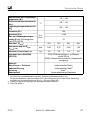
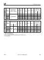
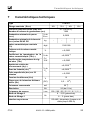
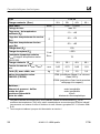
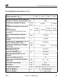
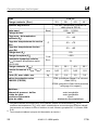
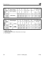
7 Specifications 25............................................
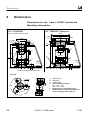
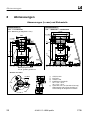
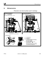
8 Dimensions (in mm, 1 mm = 0.03937 inches) 29................

Safety instructions
C16i A1461-2.0 HBM: public 3
1 Safety instructions
In cases where a breakage would cause injury to persons
or damage to equipment, the user must take appropriate
safety measures (such as fall protection, overload protec
tion, etc.). For safe and trouble‐free operation, the load
cell has to be correctly transported, stored, sited and
installed and must also be carefully operated and main
tained.
It is essential to comply with the relevant accident pre
vention regulations. In particular you should take into
account the limit loads quoted in the specifications.
Use in accordance with the regulations
The C16i... type digital load cell is conceived for weighing
applications. Use for any additional purpose shall be
deemed to be not in accordance with the regulations.
In the interests of safety, the load cell must only be oper
ated as described in the Mounting instructions. It is also
essential to observe the appropriate legal and safety reg
ulations for the application concerned during use. The
same applies to the use of accessories.
Take into account the maximum limit loads given in the
Technical data. The technical data for the load cell
applies within the specified load limits only.
The electronic system processing the measurement sig
nal must be designed such that no consequential dam
age is caused by the failure of the measurement signal.
The load cell can be used as machine components.
Please note that in these cases, in order to achieve high
sensitivity, the load cell has not been designed with the
safety factors normally applied in machine design.

Safety instructions
4 A1461-2.0 HBM: public C16i
The digital load cell is not a safety element within the
meaning of its use as intended. Proper and safe opera
tion of this load cell requires proper transportation, cor
rect storage, assembly and mounting and careful opera
tion and maintenance.
General dangers due to non‐observance of the
safety instructions
The C16i... load cell correspond to the state of the art
and are fail‐safe. The load cell can give rise to residual
dangers if it is inappropriately installed and operated by
untrained personnel.
Everyone involved with the installation, commissioning,
maintenance or repair of a force transducer must have
read and understood the Mounting Instructions and in
particular the technical safety instructions.
Residual dangers
The scope of supply and performance of the load cell
covers only a small area of weighing technology. In addi
tion, equipment planners, installers and operators should
plan, implement and respond to the safety engineering
considerations of weighing technology in such a way as
to minimize residual dangers. Prevailing regulations must
be complied with at all times. There must be reference to
the residual dangers connected with weighing technol
ogy.
Environmental conditions
In the context of your application, please note that all ma
terials which release chlorine ions will attack all grades of
stainless steel and their welding seams. In such cases
the operator must take appropriate safety measures.

Safety instructions
C16i A1461-2.0 HBM: public 5
Conversions and modifications
The load cell must not be modified from the design or
safety engineering point of view except with our express
agreement. Any modification shall exclude all liability on
our part for any damage resulting therefrom.
Qualified personnel
This load cell is only to be installed by qualified personnel
strictly in accordance with the technical data and with the
safety rules and regulations. It is also essential to ob
serve the appropriate legal and safety regulations for the
application concerned. The same applies to the use of
accessories.
Qualified personnel means persons entrusted with the
installation, fitting, commissioning and operation of the
product who possess the appropriate qualifications for
their function.
Prevention of accidents
Although the specified breaking load in the destructive
range is several times the nominal capacity, the relevant
accident prevention regulations from the trade associa
tions must be taken into consideration.

Markings used
6 A1461-2.0 HBM: public C16i
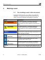
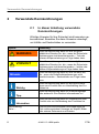
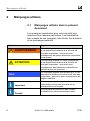
2 Markings used
2.1 The markings used in this document
Important instructions for your safety are specifically
identified. It is essential to follow these instructions in
order to prevent accidents and damage to property.
Symbol Significance
WARNING
This marking warns of a potentially dangerous
situation in which failure to comply with safety
requirements can result in death or serious physical
injury.
CAUTION
This marking warns of a potentially dangerous
situation in which failure to comply with safety
requirements can result in slight or moderate physical
injury.
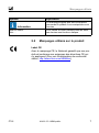
Notice
This marking draws your attention to a situation in
which failure to comply with safety requirements can
lead to damage to property.
Important
This marking draws your attention to important
information about the product or about handling the
product.
Tip
This marking indicates application tips or other
information that is useful to you.
Information
This marking draws your attention to information
about the product or about handling the product.
Emphasis
See….
Italics are used to emphasize and highlight text and
references to other chapters and external documents.


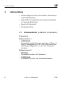
Scope of supply
8 A1461-2.0 HBM: public C16i
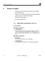
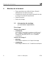
3 Scope of supply
S Pendulum load cell with connection cable, flexible
tube and tube clip
S Dowel pin for rotation stop device (Load introduction
parts have to be ordered separately)
S Plastic bag with grease
S Mounting instructions
3.1 Mounting accessories (optional)
Thrust pieces
Mounting variation 1:
S C16/ZOU44A
Thrust pieces (stainless steel) for above and below
(1 Set = 2 pcs.), for use with C16.../≤60 t up to a
max. load per load cell of 40 t, incl. 3 excentric was
hers
Mounting variation 2:
S EPO3/50t
Thrust piece for above, incl. spanner
S C16/EPU44A
Thrust piece for below, incl. 3 excentric washers

Mounting
C16i A1461-2.0 HBM: public 9
4 Mounting
General hints
S Please handle the load cell carefully.
S Use appropriate lifting gear when mounting the
weighing device.
S Do not overload the load cell, not even for a short
time (e.g. due to unevenly distributed supporting
loads).
S If required, use supporting elements (dummies) of the
same height for alignment purposes.
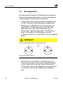
The C16i... is a pendulum load cell designed to automati
cally restore the mounting construction to a stable initial
position in the case of a lateral displacement of the load
introduction (= skewing of the load cell). The maximum
permissible lateral displacement or skewing (see chap
ter 8 “Dimensions”) must not be exceeded, otherwise the
load cells or load introduction parts might be damaged.
The easiest and most common solution for this problem
are the appropriate stops on the mounting construction
(weighing platform) which must be carefully adjusted
within the specified values.

Mounting
10 A1461-2.0 HBM: public C16i
With the C16i..., we recommend the use of EPO3/50t
and C16/EPU44A or C16/ZOU44A mounting accessories
from HBM, because they permit easy mounting. The
rotation stop device welded onto the load cells and the
dowel pin provided are also suitable for this model type
(see chapter 8 “Dimensions”).
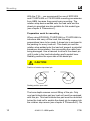
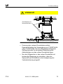
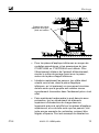
Preparation work for mounting
When using EPO3/50t, C16/EPU44A or C16/ZOU44A to
introduce and carry off the load, the following
preparations have to be made: A dowel pin is enclosed in
the packing for every load cell. This dowel pin and the
rotation stop welded onto the load cell prevent a potential
transducer microrotation, thus preventing the cable from
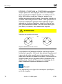
being damaged. Use a hammer to drive in the dowel pin
until it rests in the load introduction part's pocket bore.
Radially position the open side of the dowel pin.
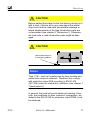
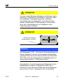
CAUTION
or
Position of rotation stop dowel pin:
Radially position open side!
The bore depth ensures correct fitting of the pin. Only
one load introduction part per load cell must be equipped
with this pin. This load introduction part must be mounted
below the load cell to enable the dowel pin to engage into
the rotation stop recess (see chapter 8 “Dimensions”). No

Mounting
C16i A1461-2.0 HBM: public 11
pin must be introduced into the bore on the upper load
introduction part.
Tip
Please also refer to and comply with the special notes at
the end of this chapter.
The areas or foundations below the lower load introduc
tion part (for carrying off the load) and above the upper
load introduction part should be as even and level as
possible.
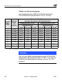
Practically drill the required borings for securing and fix
ing on the weighbridge resp. tank and base plate before
you mount the weighing platform. The dimensions for use
with EPO3/50t and C16/EPU44A or C16/ZOU44A are as
shown in the dimensioned drawings in 8.

Mounting
12 A1461-2.0 HBM: public C16i
4.1 Mounting procedure
Below, we use a weighbridge as an example for the me
chanical installation. We recommend that you proceed as
follows:
S Use appropriate lifting gear to lift one face of the
weighbridge that has already been centered.
S Prepare the load introduction parts and mount the part
with the rotation stop dowel pin below and the load
introduction part without the dowel pin above. The
lower load introduction part must be aligned such that
the dowel pin points in the direction in which, later on,
the cable outlet and the type plate are to be point,
although do not yet finally fix it.
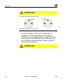
CAUTION
or
Position of rotation stop dowel pin:
Radially position open side!
S Use a sufficient amount of the grease provided with
the load cells to protect from wear, tear, dirt and
corrosion the upper and lower load introduction parts
in the load carrying element, the dowel pin and the
rotation stop on the load cell.

Mounting
C16i A1461-2.0 HBM: public 13
CAUTION
Grease load introduction
parts and dowel pin
S Fix the lower load introduction parts with a spanning
washer when using EPO3/50t or eccentric washers
when using C16/EPU44A or C16/ZOU44A. For
subsequent sealing of the flexible tube, mount the
tube clip supplied with the load cell around the lower
compression pad.
S Now insert the load cells by rotating them into the
lower load introduction part such that the dowel pin
engages into the rotation stop recess.

Mounting
14 A1461-2.0 HBM: public C16i
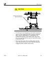
S Now let down the weighbridge carefully such that
there is just no load on the load cells and that they
can be aligned perpendicularly. At the same time,
introduce the load cells' upper load introduction parts
into the upper load carrying element. For this purpose,
you can move the lower load introduction element
with the eccentric washers loosened. We recommend
that you use an appropriate prism level to check the
load cell's perpendicular mounting position by holding
it against the cylindrical housing tube. Then let down
the bridge and proceed in the same way for the other
face.
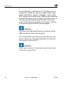
CAUTION
Align load cells vertically!
S After finishing themounting procedure, once again
check the perpendicular mounting position for all the
load cells, with the bridge swinging free and if
required, lift the bridge to correct the position. Exact
mounting is an important condition for accurate
measurements and minimum corner deviation.
S Once the final perpendicular alignment of all load cells
has been completed, turn the eccentric washers
towards the load introduction part and secure by
tightening the fixing screws.
S Turn the flexible tube already mounted on the load
cell down over the compression pad and directly fix it
on the compression pad using the tube clip.

Mounting
C16i A1461-2.0 HBM: public 15
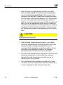
CAUTION
There is no warranty in case of un-lubricated compres
sion pads and if the flexible tube has not been mounted
correctly!
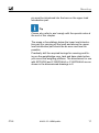
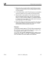
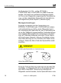
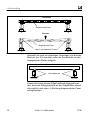
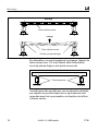
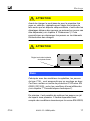
4.2 Procedure for special mounting
situations
If there are extremely long distances between the sup
ports of the load cells or if the weighbridges bend easily,
the rolling movements of the load cell produced by a load
can cause discrepancies in the results. This rolling mo
tion is assisted by a lateral drift of the upper load cell load
introduction points under load, if the contact zone be
tween the load introduction part and the load cell is far
below the neutral bending axis of the weighbridge. To
minimize the discrepancies which occur in these cases,
the load cells can be mounted at a slight slant, set to a
maximum of 1° inwards.

Mounting
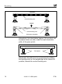
16 A1461-2.0 HBM: public C16i
neutral bending axis
unloaded
neutral bending axis
initial state (unloaded)
loaded
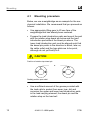
Alternatively, thin steel plates (approx. 0.5 mm thick) can
be placed under one side, under the load introduction
parts, at the given points.
Steel plates
Structurally, this effect can be counteracted by shifting
the bearing points on the weighbridge as far upward as
possible, towards the neutral bending axis.

Mounting
C16i A1461-2.0 HBM: public 17
CAUTION
Before loading the bridge for the first time by driving on it
with a truck / vehicle, do in any case adjust the lateral
stops such that the load cells' permissible skewings or
lateral displacements of the load introduction parts are
not exceeded (see chapter 8 “Dimensions”). Otherwise,
the load cells or load introduction parts might be dam
aged.
CAUTION
Adjust lateral stops of
the weighing platform
Notice
Type C16i... load cell is metal‐clad by laser‐welding and
made from rustproof materials. Therefore they comply
with protection class IP68 according to EN 60 529
(IEC 529) under the stated test conditions (see chapter 7
“Specifications”).
In general, the load cell permit steam jet cleaning. How
ever, the conditions for max. pressure, temperature, etc.,
stated in the EN 60 529 for protection class IP69K, must
be observed.

Mounting
18 A1461-2.0 HBM: public C16i
When EPO3/50t, C16/EPU44A or C16/ZOU44A mount
ing parts from HBM are used, the integral rotation stop
device, described in chapter 4 “Montage”, can be used.
With customized mounting parts, HBM provides drawings
showing the position and mounting of the rotation stop. In
this case, special attention must be paid to the obser
vance of the tolerances stated for the dowel pin position,
to prevent the load cells from being damaged.
Important
Only when the HBM specifications are followed will the
HBM warranty for the product be valid.
The C16/ZOU44A load introduction parts accessory kit
can be used as an economical alternative for load cells
with nominal loads up to 60 t.
Important
In this case, however, the maximum load for each load
cell must not exceed 40 t.
Seite laden ...
Seite laden ...
Seite laden ...
Seite laden ...
Seite laden ...
Seite laden ...
Seite laden ...
Seite laden ...
Seite laden ...
Seite laden ...
Seite laden ...
Seite laden ...
Seite laden ...
Seite laden ...
Seite laden ...
Seite laden ...
Seite laden ...
Seite laden ...
Seite laden ...
Seite laden ...
Seite laden ...
Seite laden ...
Seite laden ...
Seite laden ...
Seite laden ...
Seite laden ...
Seite laden ...
Seite laden ...
Seite laden ...
Seite laden ...
Seite laden ...
Seite laden ...
Seite laden ...
Seite laden ...
Seite laden ...
Seite laden ...
Seite laden ...
Seite laden ...
Seite laden ...
Seite laden ...
Seite laden ...
Seite laden ...
Seite laden ...
Seite laden ...
Seite laden ...
Seite laden ...
Seite laden ...
Seite laden ...
Seite laden ...
Seite laden ...
Seite laden ...
Seite laden ...
Seite laden ...
Seite laden ...
Seite laden ...
Seite laden ...
Seite laden ...
Seite laden ...
Seite laden ...
Seite laden ...
Seite laden ...
Seite laden ...
Seite laden ...
Seite laden ...
Seite laden ...
Seite laden ...
Seite laden ...
Seite laden ...
Seite laden ...
Seite laden ...
Seite laden ...
Seite laden ...
-
 1
1
-
 2
2
-
 3
3
-
 4
4
-
 5
5
-
 6
6
-
 7
7
-
 8
8
-
 9
9
-
 10
10
-
 11
11
-
 12
12
-
 13
13
-
 14
14
-
 15
15
-
 16
16
-
 17
17
-
 18
18
-
 19
19
-
 20
20
-
 21
21
-
 22
22
-
 23
23
-
 24
24
-
 25
25
-
 26
26
-
 27
27
-
 28
28
-
 29
29
-
 30
30
-
 31
31
-
 32
32
-
 33
33
-
 34
34
-
 35
35
-
 36
36
-
 37
37
-
 38
38
-
 39
39
-
 40
40
-
 41
41
-
 42
42
-
 43
43
-
 44
44
-
 45
45
-
 46
46
-
 47
47
-
 48
48
-
 49
49
-
 50
50
-
 51
51
-
 52
52
-
 53
53
-
 54
54
-
 55
55
-
 56
56
-
 57
57
-
 58
58
-
 59
59
-
 60
60
-
 61
61
-
 62
62
-
 63
63
-
 64
64
-
 65
65
-
 66
66
-
 67
67
-
 68
68
-
 69
69
-
 70
70
-
 71
71
-
 72
72
-
 73
73
-
 74
74
-
 75
75
-
 76
76
-
 77
77
-
 78
78
-
 79
79
-
 80
80
-
 81
81
-
 82
82
-
 83
83
-
 84
84
-
 85
85
-
 86
86
-
 87
87
-
 88
88
-
 89
89
-
 90
90
-
 91
91
-
 92
92


HBM C16i D1 Mounting instructions
- Typ
- Mounting instructions
- Dieses Handbuch ist auch geeignet für
in anderen Sprachen
- English: HBM C16i D1
- français: HBM C16i D1
Verwandte Papiere
Sonstige Unterlagen
-
Baumer Rotation lock M40 VA4 IP69K Datenblatt
-
 Minebea Intec Pendeo® Process-Digital Precision Compression Load Cell PR 6204 Bedienungsanleitung
-
 Minebea Intec Weighbridge Load Cell PR 6221 Bedienungsanleitung
-
 Minebea Intec Compression load cell Inteco® PR 6203 Bedienungsanleitung
-
ABB Emax Series Benutzerhandbuch
-
Haier HBM-687XNF Benutzerhandbuch
-
Sony Ericsson HBM-30 Benutzerhandbuch
-
Mettler Toledo IND246 Terminal Installationsanleitung
-
LG Optimus L9 - LG P760 Benutzerhandbuch
-
 LG HBM Tone Ultra Benutzerhandbuch


