
443 398 --002 9703 Valid from Machine no 452 XXX--XXXX
A6 SFD1
Auto matic welding machine
Schweißautomat
Appareil de soudage automatique
Lasautomaat
Operating manual
Bedienungsanleitung
Manuel de l’opérateur
Gebruikershandboek

SAFETY 2..............................................
TECHNICAL DESCRIPTION 3.............................
INSTALLATION 4........................................
OPERATION 9..........................................
MAINTENANCE 10........................................
TROUBLESHOOTING 11..................................
CONNECTION INSTRUCTIONS FOR PEG1 AND A6 VEC 12..
SICHERHEIT 14..........................................
TECHNISCHE BESCHREIBUNG 15.........................
INSTALLATION 16........................................
BETRIEB 21..............................................
WARTUNG 22............................................
FEHLERSUCHE 23.......................................
ANSCHLUSSANLEITUNG FÜR PEG1 UND A6 VEC 24.......
SECURITE 26............................................
DESCRIPTION TECHNIQUE 27............................
INSTALLATION 28........................................
MISE EN SERVICE 33.....................................
ENTRETIEN 34...........................................
RECHERCHE DE PANNES 35..............................
INSTRUCTIONS DE BRANCHEMENT POUR PEG1 ET A6 VEC 36
VEILIGHEID 38...........................................
TECHNISCHE BESCHRIJVING 39..........................
INSTALLATIE 40..........................................
GEBRUIK 45.............................................
ONDERHOUD 46.........................................
STORINGZOEKEN 47.....................................
INSCHAKELINSTRUCTIES VOOR PEG1 EN A6 VEC 48......
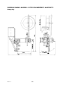
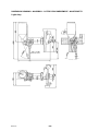
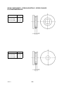
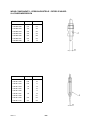
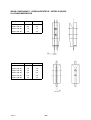
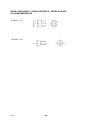
DIMENSION DRAWING - MASSBILD -
COTES D’ENCOMBREMENT - MAATSCHETS 49......
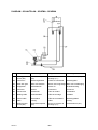
DIAGRAM - SCHALTPLAN - SCHÉMA - SCHEMA 51.........
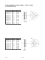
WEAR COMPONENTS - VERSCHLEISSTEILE -
PIÈCES D’USURE - SLIJTAGEONDERDELEN 52......
Rights reserved to alter specifications without notice.
Änderungen vorbehalten.
Sous réserve de modifications sans avis préalable.
Recht op wijzigingen zonder voorafgaande medeleling voorbehouden.

-- 1 --
mmvarnea
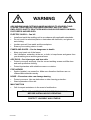
WARNING
ARC WELDING AND CUTTING CAN BE INJURIOUS TO YOURSELF AND
OTHERS. TAKE PRECAUTIONS WHEN WELDING. ASK FOR YOUR
EMPLOYER’S SAFETY PRACTICES WHICH SHOULD BE BASED ON MANU--
FACTURER’S HAZARD DATA.
ELECTRIC SHOCK -- Can kill
S Install and earth the welding unit in accordance with applicable standards.
S Do not touch live electrical parts or electrodes with bare skin, wet gloves or
wet cloth ing.
S Insulate yourself from earth and the workpiece.
S Ensure your working stance is safe.
FUMES AND GASES -- Can be dangerous to health
S Keep your head out of the fumes.
S Use ventilation, extraction at the arc, or both, to keep fumes and gases from
your breathing zone and the general area.
ARC RAYS -- Can injure eyes and b u rn skin
S Protect your eyes and body. Use the correct welding screen and filter lens
and wear protective clothing.
S Protect bystanders with suitable screens or curtains.
FIRE HAZARD
S Sparks (spatter) can cause fire. Make sure therefore that there are no
inflammable materials nearby.
NOISE -- Excessive no ise can damage hearing
S Protect your ears. Use ear defenders or other hearing protection.
S Warn bystanders of the risk.
MALFUNCTION
S Call for expert assistance in the event of malfunction.
READ AND UNDERSTAND THE OPERATING MANUAL
BEFORE INSTALLING OR OPERATING.
PROTECT YOURSELF AND OTHERS!

SAFETY
-- 2 --
df00f1ea
SAFETY
Users of ESAB automatic welding machines have ultimate responsibility for ensuring
that anyone who works on or near the equipment observes all the relevant safety
precautions.
The following recommendations should be observed in addition to the standard re-
gulations that apply to the work place.
All work must be carried out according to the specified instructions by personnel who
are thoroughly familiar with the operation of the welding machine.
Incorrect or unintentional operation of the equipment may lead to a hazardous situ -
ation which can result in injury to the operator and damage to the equipment.
1. Anyone who uses the automatic welding machine must be familiar with:
S its operation
S the location of emergency stops
S its function
S relevant safety precautions
To make this easier each switch, pushbutton or potentiometer is marked with a
symbol or text that indicates its function when activated.
2. The operator must ensure that:
S no unauthorized person is stationed within the working area of the machine
when it is started up.
S that no--one is in a hazardous position when the carriage or slide mechan-
isms are operated.
3. The work place must:
S be clear of mechanical components, tools, or other obstructions that could
prevent the operator from moving freely within the working area.
S be organized so that there is free access to the emergency stop.
4. Personal safety equipment
S Always wear recommended personal safety equipment, such as safety
glasses, flame--proof clothing, safety gloves.
S Do not wear loose--fitting items, such as scarves, bracelets, etc., which could
become trapped.
5. General precautions
Live electrical components are normally shielded from accidental contact.
S Make sure the return cable is connected securely.
S Work on high voltage components may only be carried out by a qualified
electrician.
S Appropriate fire extinguishing equipment must be clearly marked and close
at hand.
S Lubrication and maintenance must not be carried out on the equipment dur-
ing its operation.

TECHNICAL DESCRIPTION
-- 3 --
dfa3d1ea
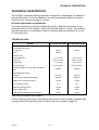
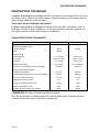
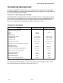
TECHNICAL DESCRIPTION
The A6 SFD1 automatic welding machine is designed for submerged arc welding of
butt and fillet joints. It can be installed on a carrier arrangem ent such as a column
and boom or a carriage running on a beam.
All other applications are prohibited.
The welding machine should be installed using bolts. (Make sure the bolts do not
touch the bottom of the insulator, which has a thread depth of 14 mm). The machine
must be mounted on a rigid base so that it is securely attached and there is no risk
of it working loose.
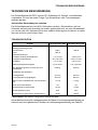
TECHNICAL DATA
A6 SFD1 LD (Light Duty) D20 HD (Heavy Duty) D35
Permissible load AC/DC
continuous 800 A 1500 A
60% 1000 A --
Electrode size
solid single wire 1,6--4,0 mm 3,0--6,0 mm
twin wire 2x1,2--2,5 mm 2x2,0--3,0 mm
hollow wire 1,6--4,0 mm 3,0--4,0 mm
Wire feed speed 0,5--9 m/min 0,2--4,5 m/min
Electrode weight, max.,mounted on welding
head
2x30 kg 2x30 kg
Slide adjustment range *
manual 210 mm 210 mm
motor--driven (with ball bearings) 300 mm 300 mm
Weight (excl. electrode and flux) 110 kg 110 kg
Flux container volume 10 l 10 l
Brake hub braking torque 1,5 Nm 1,5 Nm
Supply voltage (AC) 42 V 42 V
Continuous A--weighted noise pressure 68 dB 68 dB
*NOTEother lengths are available!
See the dimensional sketch for the heavy duty version of the manually operated slide
on page 49 and the light duty version of the motor--driven slide on page 50.

INSTALLATION
-- 4 --
dfa3i1ea
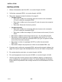
INSTALLATION
1. Motor with gear A6 VEC, see manual 443 393.
2. Control box PEG1, see manual 443 392.
3. Connect the welding machine as shown in the diagram on page 51.
S Rectifier:
G Connect the control cable (08) between the welding power source (01)
and control box PEG1.
G Connect the cable lugs on the cable (07) between the welding power
source and the shunt.
G Connect the electrode to the positive terminal.
S Alternating current:
G Connect the control cable (08) between the welding power source (01)
and the control box PEG1 (02).
G Connect the welding cable (07) between the welding power source (10)
and the shunt.
S Connect the return cable between the welding power source (01, 10) and the
workpiece.
S Connect the measuring cable (09) between the workpiece and the welding
power source (01, 10) or between the workpiece and the control box PEG1
(02) (e.g. if a welding power source of a different make is used).
S Connect the motor and gears A6 VEC to the control box PEG1 (02).
S Connect the projector lamp, if used, to the control box PEG1 (02).
4. Check that the control box PEG1 is connected as shown in the table on page 12
and that the gear ratio and rotor speed are as specified there.
5. If a motor--driven slide is used, see manual 443 394.
6. If joint following equipment A6 GMD is used, see manual 443 403.
7. Choose the electrode type and flux to give a weld m etal analysis that roughly
matches the base material. Choose the size of electrode and welding para -
meters according to the recommendations of the consumable manufacturer.

INSTALLATION
-- 5 --
dfa3i1ea
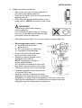
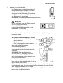
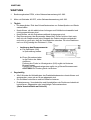
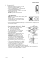
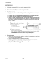
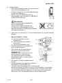
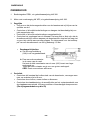
8. Loading the welding electrode.
S Removethewirereelfromthebrakehub(2)
and remove the backing plate (3).
S Place the coil of wire (1) on the reel and refit the
backing plate (3).
S Fit the wire reel and disposable bobbin on the
brake hub (2). CHECK the position of the carrier.
IMPORTANT!
To prevent the wire bobbin slipping
off the brake hub:
Lock the bobbin in place using the red knob,
as shown on the label (see drawing on right)
positioned next to the brake hub.
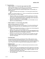
S Check that the feed roller (1) and contact jaws (4) are the right size.
S When using heavy wire (3 -- 6 mm):
a. Cut off the ties around the
electrode coil.
b. Pull out the end of the electrode.
c. Straighten out the electrode.
S Position the end of the electrode in
the groove in the feed rollers.
S Adjustthepressureexertedonthe
electrode by the roller (6).
NOTE! Only tighten it enough to
ensure reliable feeding.
Do not tighten the pressure screw all the
way, leave some movement in the spring.
S The spacer bolt (3) must not be removed.
S Feed the electrode forward using switch
A02onthePEG1box.
S While the electrode is being fed forwards,
straighten it out using the knob (5) on the wire
straightener, or using a special straightener for thin wire or twin wire.
When the wire straightener is correctly set the wire should come out
straight through the contact jaws and contact tip.

INSTALLATION
-- 6 --
dfa3i1ea
9. Changing the wire feed roller (see wear components on page 52).
S Single wire:
G Unscrew the knob (5) and pressure screw (6).
G Unscrew the handwheel (2).
G Replace the feed roller. The wire size is marked on the roller.
S Twin wire:
G Replace twin wire feed rollers in the same way as for single wire rollers.
G NOTE! Replace the pressure roller at the same time. The special spheri-
cal rollers for twin wire replace the standard pressure roller for single
wire.
G Fit the pressure roller with the special shaft stud
(order no. 146 253--001).
S Tube wire (for knurled rollers):
G Replace the feed roller and pressure in pairs for the chosen wire size.
NOTE! A special shaft stud is required for the pressure roller (order no.
2129 011--01).
G Tighten the pressure screw to a moderate pressure so that the tube wire
is not deformed.
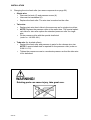
WARNING!
Rotating parts can cause injury, take great care.

INSTALLATION
-- 7 --
dfa3i1ea
10. Contact equipment
S Single wire 1,6 -- 2,5 mm (4,0 mm). Light duty (D20)
Supplied as standard with A6 SFD1 (LD version) and used as necessary,
e.g. in restricted spaces, wire sizes up to 4,0 mm.
Use contact tube D20 with contact tip (M12 thread), see table on page 54.
G Tighten the contact tip using spanner no. 10 to ensure a good contact.
For thinner wires, e.g. ø1,6 -- 2,5 mm, use a guide tube and separate thin
wire straightener.
G Fit the clamp for the guide tube in the M12 hole for the fixed straighten-
ing roller on the standard wire straightener. The guide tube should bot-
tom against the contact tip. Trim the length so that the distance to the
feed roller is about 5 mm.
G Install the thin wire straightener above the clamp for the wire straigh-
tener.
S Single wire 3,0 -- 6,0 mm. Heavy duty (D35)
Included as standard with A6 SFD1.
Use contact tube D35 with contact jaws. See also the remarks about contact
tube D20 for wires up to 4 mm in restricted spaces.
G Use a standard straightener with the A6, consisting of one fixed and one
adjustable roller.
G Assemble the contact jaws using the M5 bolts supplied, one part of the
contact jaws on the fixed part of the contact tube and the other part on
the loose half of the split contact tube.
G Install the loose half with the contact jaw in place using the M8 hex head
bolts and tighten fully to ensure good contact between the contact jaws
and the electrode.
S Tube electrodes.
Contact tubes D20 och D35 can be used for tube electrode. If contact jaws
(D35) are used they should be tightened to a moderate pressure only to
avoid deforming the tube electrode. Make sure that good electrical contact is
achieved with the electrode.
S Twin wire.
Always use contact tube D35 for twin wire with a guide tube and separate
straightener.
G Fit the clamp for the guide tube in the M12 hole for the fixed straighten-
ing rollers on the standard wire straightener. The guide tubes should bot-
tom against the contact jaws (Heavy Twin) or against the adapter for the
contact tip (Light Twin).
G Trim the length of the guide tubes so that the distance to the feed rollers
is around 5 mm.

INSTALLATION
-- 8 --
dfa3i1ea
S Twin wire 2x1,2 -- 2x2,0 mm, Light Twin:
Use two contact tips with M6 threads. For the correct wire sizes see the table
on page 54.
G Tighten the contact tips well, to ensure a good electrical contact.
G Fit the adapter for the M6 contact tip to the fixed half of the split contact
tube using M5 bolts. The pressure screw and loose half of the contact
tube are not required for this application.
S Twin wire 2x2,0 -- 2x3,0 mm, Heavy Twin:
G Use Twin contact jaws, for heavy electrodes (2x2,0 mm), see also Light
Twin.
G Fit the contact jaws using the M5 bolts provided. NOTE! Fit the half of the
contact jaws with the projection in the fixed half of the contact tube.
G Remove the loose half of the contact tube when fitting new wire by undo-
ing the pressure screw.
G Feed the wire down and guide it into the groove in the fixed half of the
contact jaws (with projection).
G Undo the M5 bolts that hold the contact jaws and fit the loose half using
the M8 Allen bolt, so that both halves of the contact jaws surround the
electrode. Tighten the loose half of the contact jaws in place using the
M5 bolts to ensure good electrical contact.
S Adjusting the wires during Twin--arc welding:
Adjust the positions of the wires in the joint by rotating the contact tip. Both
wires can be rotated so that they are in line with the joint, or up to 90_across
the joint, i.e. one wire either side of the joint.
11. Filling up with flux
S Close the flux valve on the flux container.
S Remove the separator for the flux pump, if fitted. Fill with flux.
NOTE! The flux must be dry. If possible, avoid using agglomerated flux out-
side or in humid environments.
S Adjust the height of the flux nozzle above the weld to give the correct amount
of flux. The flux cover should be thick enough so that the arc cannot pen-
etrate it.

OPERATION
-- 9 --
dfa3o1ea
OPERATION
1. Careful joint preparation is essential for good welding results.
NOTE! The gap in the weld joint must be uniform.
2. To minimize the risk of hot cracking the width of the weld should be larger than
the penetration.
3. Always weld a test piece with the same joint preparation and plate thickness as
the intended production piece.
NOTE! NEVER make a trial weld on a production work piece.
Operating instructions for control box PEG1
See operating manual PEG1 order no. 443 392.

MAINTENANCE
-- 1 0 --
dfa3m1ea
MAINTENANCE
1. Control box PEG1, see manual 443 392.
2. Motor with gear A6 VEC, see manual 443 393.
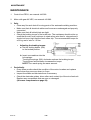
3. Daily
S Clean any flux and dust off moving parts of the automatic welding machine.
S Make sure that all electrical cables and hoses are undamaged and properly
connected.
S Make sure that all bolted joints are tight.
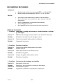
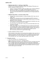
S Check the braking torque of the brake hub. The resistance should not be so
small that the wire reel continues to rotate when wire feed is stopped and it
should not be so high that the feed rollers slip. The recommended torque for
a30kgreelofwireis1.5Nm.
G Adjusting the braking torque:
a. Set the locking button (006)
to the locked position.
b. Insert a screwdriver into the
hub springs.
Turning the springs (002) clockwise reduces the braking torque.
Turning them anticlockwise increases the torque.
NOTE! Turn each spring the same amount.
4. Periodically
S Every three months check the condition of the motor brushes and replace
them when they are worn down to 6 mm.
S Inspect the slides and lubricate them if necessary.
S Check the electrode guides, drive rollers and contact tip of the wire feed unit.
Replace any components that are worn or damaged.
(See wear components on page 52)
aza5dp08

TROUBLESHOOTING
-- 1 1 --
dfa3f1ea
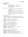
TROUBLESHOOTING
Equipment
S Manual for control box PEG1, order no. 443 392.
S Manual for motor with gear A6 VEC, order no. 443 393.
Check
S that the welding power supply is connected for the correct mains
voltage
S that all three phases are giving the correct voltage
(phase sequence not important)
S that the welding cables and connections to them are not damaged
S that the controls are in the right positions
S that the mains supply is disconnected before starting repairs
POSSIBLE FAULTS
1. Symptom Current and voltage show fluctuating values on digital display.
Cause 1.1 Contact jaws or contact tip are worn or wrong size.
Action Replace contact jaws or contact tip.
Cause 1.2 Pressure on feed rollers is inadequate.
Action Increase pressure on feed rollers.
2. Sympto m Wire feed is irregular.
Cause 2.1 Pressure on feed rollers is incorrectly adjusted.
Action Adjust pressure on feed rollers.
Cause 2.2 Feed rollers wrong size.
Action Change feed rollers.
Cause 2.3 Groove in feed rollers is worn.
Action Replace feed rollers.
3. Symptom Welding cables overheat.
Cause 3.1 Poor electrical connection.
Action Clean and tighten all electrical connections.
Cause 3.2 Welding cables too small.
Action Increase dimension of cables or use parallel cables.

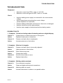
12
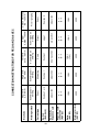
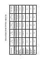
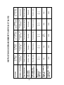
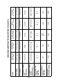
CONNECTION INSTRUCTIONS FOR PEG1 AND A6 VEC
Electrode
Single wire
2,5 - 6mm
Single wire
2,5 - 6mm
Twin wire
2x1,2 - 3,0mm
Strip.br.
0,5x30 - 100mm
Carbon electrode
8,0 - 12,7mm
Weldin g method
Submerged arc
welding
Submerged arc
welding
Submerged arc
welding
Submerged arc
welding
Arc air gouging
Current type Direct Alternating Direct Direct Direct
Switch
(feed-back)
Position1or2 Position 1 Position 1 Läge 1 Position 2
Switch (9),
Sequence card
Up position Up position Down position Up position Up position
Regulator card
connectio n
(A6 VEC)
X--1
B--7
X--1
B--7
X--1
B--7
X--1
B--7
X--1
B--7
Ratio
(A6 VEC)
156:1 156:1
156:1
(74:1)
156:1 156:1
Motor rotor r/min
(A6 VEC)
4000 4000 4000 4000 4000

-- 1 3 --
mmvarnga
WARNUNG
BEIM LICHTBOGENSCHWEIßEN UND LICHTBOGENSCHNEIDEN KANN IHNEN
UND ANDEREN SCHADEN ZUGEFÜGT WERDEN. DESHALB MÜSSEN SIE BEI
DIESEN ARBEITEN BESONDERS VORSICHTIG SEIN. BEFOLGEN SIE DIE
SICHERHEITSVORSCHRIFTEN IHRES ARBEITGEBERS, DIE SICH AUF DEN
WARNUNGSTEXT DES HERSTELLERS BEZIEHEN.
ELEKTRISCHER SCHLAG -- Kann den Tod bringen.
S Die Schweißausrüstung gemäß örtlichen Standards installieren und erden.
S Keine Stromführenden Teile oder Elektroden mit bloßen Händen oder mit nasser
Schutzausrüstung berühren.
S Personen müssen sich selbst von Erde und Werkstück isolieren.
S Der Arbeitsplatz muß sicher sein.
RAUCH UND GAS -- Können Ihre Gesundheit gefährden.
S Das Angesicht ist vom Schweißrauch wegzudrehen.
S Ventilieren Sie und saugen Sie den Rauch aus dem Arbeitsbereich ab.
UV-- UND IR--LICHT -- Können Brandschäden an Augen und Haut verursachen
S Augen und Körper schützen. Geeigneten Schutzhelm mit Filtereinsatz und
Schutzkleider tragen.
S Übriges Personal in der Nähe, ist durch Schutzwände oder Vorhänge zu
schützen.
FEUERGEFAHR
S Schweißfunken können ein F euer entzünden. Daher ist dafür zu sorgen, daß
sich am Schweißarbeitsplatz keine brennbaren Gegenstände befinden.
GERÄUSCHE -- Übermäßige Geräusche können Gehö rschäden verursachen
S Schützen Sie ihre Ohren. Benutzen Sie Kapselgehörschützer oder andere
Gehörschützer.
S Warnen Sie Umstehende vor der Gefahr.
BEI STÖRUNGEN
S Nur Fachleute mit der Behebung von Störungen beauftragen.
LESEN SIE DIE BETRIEBSANWEISUNG VOR DER
INSTALLATION UND INBETRIEBNAHME DURCH.
SCHÜTZEN SIE SICH SELBST UND ANDERE!

SICHERHEIT
-- 1 4 --
df00f1ga
SICHERHEIT
Der Anwender eines ESAB--Schweißautomaten ist verantwortlich für die Sicherheits-
maßnahmen, die für das Personal gelten, das mit der Anlage oder in deren Nähe ar-
beitet.
Der Inhalt dieser Empfehlung kann als eine Ergänzung der normalen Vorschriften für
den Arbeitsplatz betrachtet werden.
Die Bedienung muß nach gegebenen Anleitungen von Personal ausgeführt werden,
das mit den Funktionen des Schweißautomaten gut vertraut ist.
Ein falsches Manöver, verursacht durch einen fehlerhaften Handgriff, oder die fehler-
hafte Auslösung einer Funktionssequenz, kann eine unnormale Situation herbeifüh-
ren, die Personen-- und maschinellen Sachschaden verursachen kann.
1. Personal, das mit dem Schweißautomaten arbeitet, soll gut vertraut sein mit:
S dessen Handhabung
S dem Standort des Notausschalters
S der Funktion
S den geltenden Sicherheitsvorschriften
Um die Bedienung zu erleichtern, ist jeder elektr. Schalter, Druckknopf oder je-
des Potentiometer mit einem Schild versehen, auf dem der Typ der aktivierten
Bewegung oder der Einschaltung bei Betrieb angegeben sind.
2. Der Bediener soll sicherstellen:
S daß sich kein Unbefugter im Arbeitsbereich des Schweißautomaten befindet,
bevor dieser eingeschaltet wird.
S daß keine Person an der falschen Stelle steht, wenn der Wagen oder Schlit-
ten gefahren wird.
3. Der Arbeitsplatz soll:
S frei von Maschinenteilen, Werkzeugen oder anderen Materialen sein, so daß
der Bediener nicht bei der Arbeit im Arbeitsbereich behindert wird.
S mit einem Notausschalter versehen sein, der leicht zugänglich ist.
4. Persönliche Schutzausrüstung
S Immer die vorgeschriebene, persönliche Schutzausrüstung wie z.B. Schutz-
brille, feuersichere Arbeitskleidung, Schutzhandschuhe tragen.
S Sicherstellen, daß keine lose getragenen Gegenstände wie Gürtel, Armbän-
der usw. hängenbleiben.
5. Sonstiges
Stromführende Teile sind normalerweise berührungsgeschützt.
S Kontrollieren, ob der angewiesene Rückleiter gut angeschlossen ist.
S Eingriffe in elektr. Geräten dürfen nu r von einem Elektriker vorgenommen
werden.
S Erforderliche F euerlöschausrüstung muß an einem gut sichtbaren Platz
leicht zugänglich sein.
S Schmierung und Wartung des Schweißautomaten darf nicht während des
Betriebs erfolgen.

TECHNISCHE BESCHREIBUNG
-- 1 5 --
dfa3d1ga
TECHNISCHE BESCHREIBUNG
Der Schweißutomat A6 SFD1 ist zum UP--Schweißen für Stumpf -- und Kehlnähte
vorgesehen. Er kann an einem Träger, Typ Schweißkran oder Traversenwagen,
montiert werden.
Jede andere Anwendung ist verboten.
Der Schweißautomat wird mit M12--Schrauben montiert. (Sicherstellen, daß die
Schraube nicht bis zum Anschlag im Isolator geschraubt wird, der eine Gewindetiefe
von 14 mm hat). Der Automat ist auf einer stabilen Unterlage zu montieren, so daßer
fest ruht und sich nicht lockern kann.
TECHNISCHE DATEN
A6 SFD1 LD (Light Duty) D20 HD (Heavy Duty) D35
Zulässige Belastung AC/DC
kontinuierlich 800 A 1500 A
60% 1000 A --
Elektrodendimension
Volldraht einfache Drahtelektrode 1,6--4,0 mm 3,0--6,0 mm
doppelte Drahtelektrode 2x1,2--2,5 mm 2x2,0--3,0 mm
Fülldraht 1,6--4,0 mm 3,0--4,0 mm
Drahtvorschubgeschwindigkeit 0,5--9 m/min 0,2--4,5 m/min
Max. Elektrodengewicht, montiert auf dem
Schweißkopf
2x30 kg 2x30 kg
Einstellänge des Schlittens *
handgetrieben 210 mm 210 mm
motorgetrieben (kugelgelagert) 300 mm 300 mm
Gewicht (exkl. Drahtelektrode und Schweißpul-
ver)
110 kg 110 kg
Inhalt des Pulverbehälters 10 l 10 l
Bremsmoment der Bremsnabe 1,5 Nm 1,5 Nm
Anschlußspannung (AC) 42 V 42 V
Kontinuierlich A--gemessener Geräuschdruck 68 dB 68 dB
* ACHTUNG Eine andere Länge kann bestellt werden!
Siehe Maßzeichnung für handgesteuerten Schlitten in Hochleistungsausführung auf
Seite 49 und motorgesteuerten Schlitten in Hochleistungsausführung auf Seite 50.

INSTALLATION
-- 1 6 --
dfa3i1ga
INSTALLATION
1. Motor mit Getriebe A6 VEC, siehe Gebrauchsanweisung 443 393.
2. Bedienungskasten PEG1, siehe Gebrauchsanweisung 443 392.
3. Den Schweißautomaten gemäß Schema auf Seite 51 anschließen.
S Gleichstrom:
G Steuerkabel (08) zwischen Schweißstromquelle (01) und Bedienungs-
kasten PEG1 anschließen.
G Mit Kabelschuh versehene Leitung (07) zwischen Schweißstromquelle
und Shunt anschließen.
G Drahtelektrode am Pluspol anschließen.
S Wechselstrom:
G Steuerkabel (08) zwischen Schweißstromquelle (01) und Bedienungs-
kasten PEG1 (02) anschließen.
G Schweißleitung (07) zwischen Schweißstromquelle (10) und Shunt an-
schließen.
S Rückleiter zwischen Schweißstromquelle (01, 10) und Werkstück anschlie-
ßen.
S Meßleitung (09) zwischen Werkstück und Schweißstromquelle (01, 10) oder
zwischen Werkstück und Bedienungskasten PEG1 (02) anschließen
(wenn z.B. ein anderes Stromquellenfabrikat verwendet wird).
S Motor mit dem Getriebe A6 VEC an den Bedienungskasten PEG1 (02)
anschließen.
S Eine Projektorlampe an den Bedienungskasten PEG1 (02) anschließen.
4. Kontrollieren, ob der Bedienungskasten PEG1 gemäß Tabelle auf Seite 24
angeschlossen ist, und dass Übersetzung und Ankerdrehzahl gemän du.
Tabelle gewählt wurden.
5. Ist ein motorgesteuerter Schlitten einbegriffen, siehe Gebrauchsanweisung
443 394.
6. Ist das Fugenabtastgerät A6 GMD einbegriffen, siehe Gebrauchsanweisung
443 403.
7. Drahtelektrodentyp und Schweißpulver so wählen, daß das Eigenschweißgut im
großen und ganzen analysenmäßig mit dem Grundmaterial übereinstimmt.
Drahtdimension und Schweißdaten sind gemäß den empfohlenen Werten des
Herstellers zu wählen.

INSTALLATION
-- 1 7 --
dfa3i1ga
8. Ladung des Schweißdrahts.
S Die Drahttrommel von der Bremsnabe (2)
demontieren und die Stirnseite (3) lösen.
S Die Drahtspule (1) an der Drahttrommel
anbringen und die Stirnseite (3) montieren .
S Die Drahttrommel bzw. die Einwegbobine auf
der Bemsnabe (2) montieren.
ACHTUNG! Die Stellung des Mitnehmers beachten.
WICHTIG!
Um zu verhindern, daß die Drahttrommel
von der Bremsnabe rutscht:
Lås ist die Drahttrommel mit dem roten
Drehgriff gemäß Warnaufkleber an der
Bremsnabe zu verriegeln
(siehe nebenstehende Abb.)
S Kontrollieren, ob Vorschubrolle (1) und Kontaktbacken (4) die richtige
Dimension haben.
S Bei dicken Drahtelektroden (3 -- 6 mm):
a. Den Bindedraht an der Drahtspule
durchschneiden
b. Das Drahtende vorziehen.
c. Den Vorbiegeradius gerade machen.
S Den Draht in die Führung der
Vorschubrolle einsetzen.
S Den Druck der Drahtelektrode zur
Vorschubrolle mit der Druckschraube (6)
einstellen.
ACHTUNG! Nicht straffer spannen
als erforderlich ist, um einen sicheren
Vorschub zu erhalten. Die Druckschraube
darf nicht schwer zu drehen sein, sie muß
noch ein bißchen federn.
S Der Paßbolzen (3) darf nicht demontiert werden.
S Den Draht mit dem elektr. Schalter A 02 am
PEG1--Kasten vorschieben.
S Während des Vorschubs der Drahtelektrode, ist diese mit dem Hebel (5) am
Richtrollenwerk oder mit einem speziellen Drahtrichtwerk für kleine Drähte
oder Doppeldrahtelektroden zu richten.
Wenn die Richtung richtig eingestellt ist, kommt der Draht durch die Kontakt-
backen bzw. Kontaktdüse hervor.

INSTALLATION
-- 1 8 --
dfa3i1ga
9. Austausch der Vorschubrolle. (siehe Verschleißteile auf Seite 52).
S Einfachdrahtelektrode:
G Drehgriff (5) und Druckschraube (6) lösen.
G Handrad (2) lösen.
G Vorschubrolle austauschen. Die Rollen sind mit der jeweiligen Draht-
dimension markiert.
S Doppeldrahtelektrode:
G Vorschubrolle mit doppelten Führungen genauso wie bei der Einfach-
drahtelektrode austauschen.
G ACHTUNG! Auch die Druckrolle austauschen. Die spezielle sphärische
Druckrolle für doppelten Draht ersetzt die Standarddruckrolle für Einfach-
draht.
G Die Druckrolle mit einem speziellen Achszapfen montieren (bestel. --Nr.
146 253--001).
S Fülldraht (für gerändelte Rollen) :
G Vorschubrolle und Druckrolle für die jeweilige Drahtdimension paarweise
austauschen ACHTUNG! Für die Druckrolle ist ein spezieller Achszapfen
erforderlich (bestel. --Nr. 2129 011--01)
G Druckschraube mit mäßigem Druck festziehen, so daß die Drahtelektro-
de nicht deformiert wird.
WARNUNG!
Bei rotierenden Teilen besteht Klemmgefahr, deshalb ist beson-
dere Vorsicht
geboten
Seite wird geladen ...
Seite wird geladen ...
Seite wird geladen ...
Seite wird geladen ...
Seite wird geladen ...
Seite wird geladen ...
Seite wird geladen ...
Seite wird geladen ...
Seite wird geladen ...
Seite wird geladen ...
Seite wird geladen ...
Seite wird geladen ...
Seite wird geladen ...
Seite wird geladen ...
Seite wird geladen ...
Seite wird geladen ...
Seite wird geladen ...
Seite wird geladen ...
Seite wird geladen ...
Seite wird geladen ...
Seite wird geladen ...
Seite wird geladen ...
Seite wird geladen ...
Seite wird geladen ...
Seite wird geladen ...
Seite wird geladen ...
Seite wird geladen ...
Seite wird geladen ...
Seite wird geladen ...
Seite wird geladen ...
Seite wird geladen ...
Seite wird geladen ...
Seite wird geladen ...
Seite wird geladen ...
Seite wird geladen ...
Seite wird geladen ...
Seite wird geladen ...
Seite wird geladen ...
Seite wird geladen ...
Seite wird geladen ...
-
 1
1
-
 2
2
-
 3
3
-
 4
4
-
 5
5
-
 6
6
-
 7
7
-
 8
8
-
 9
9
-
 10
10
-
 11
11
-
 12
12
-
 13
13
-
 14
14
-
 15
15
-
 16
16
-
 17
17
-
 18
18
-
 19
19
-
 20
20
-
 21
21
-
 22
22
-
 23
23
-
 24
24
-
 25
25
-
 26
26
-
 27
27
-
 28
28
-
 29
29
-
 30
30
-
 31
31
-
 32
32
-
 33
33
-
 34
34
-
 35
35
-
 36
36
-
 37
37
-
 38
38
-
 39
39
-
 40
40
-
 41
41
-
 42
42
-
 43
43
-
 44
44
-
 45
45
-
 46
46
-
 47
47
-
 48
48
-
 49
49
-
 50
50
-
 51
51
-
 52
52
-
 53
53
-
 54
54
-
 55
55
-
 56
56
-
 57
57
-
 58
58
-
 59
59
-
 60
60


in anderen Sprachen
- English: ESAB A6 SFD1 User manual
- français: ESAB A6 SFD1 Manuel utilisateur
- Nederlands: ESAB A6 SFD1 Handleiding
Verwandte Artikel
-
ESAB A6 SFF1C Compact 500 Benutzerhandbuch
-
-
ESAB A6 SFD2 Benutzerhandbuch
-
-
-
-
-
-
ESAB A6 Mastertrac Benutzerhandbuch
-