Bresser 7007330 Bedienungsanleitung
- Kategorie
- Wecker
- Typ
- Bedienungsanleitung

Weather Station · Wetterstation ·
Neomeo Colour
EN Instruction manual
DE Bedienungsanleitung

DE
Besuchen Sie unsere Website über den folgenden QR Code oder Weblink um weitere
Informationen zu diesem Produkt oder die verfügbaren Übersetzungen dieser Anleitung zu
finden.
EN
Visit our website via the following QR Code or web link to find further information on this
product or the available translations of these instructions.
FR
Si vous souhaitez obtenir plus d’informations concernant ce produit ou rechercher ce mode
d’emploi en d’autres langues, rendez-vous sur notre site Internet en utilisant le code QR ou le
lien correspondant.
NL
Bezoek onze internetpagina via de volgende QR-code of weblink, voor meer informatie over dit
product of de beschikbare vertalingen van deze gebruiksaanwijzing.
ES
¿Desearía recibir unas instrucciones de uso completas sobre este producto en un idioma
determinado? Entonces visite nuestra página web utilizando el siguiente enlace (código QR)
para ver las versiones disponibles.
IT
Desidera ricevere informazioni esaustive su questo prodotto in una lingua specifica? Venga
a visitare il nostro sito Web al seguente link (codice QR Code) per conoscere le versioni
disponibili.
www.bresser.de/P7007330
www.bresser.de/warranty_terms
GARANTIE · WARRANTY · GARANTÍA · GARANZIA


4 / 32
1 Imprint (German)
Bresser GmbH
Gutenbergstr. 2
46414
Rhede
Germany
www.bresser.de
For any warranty claims or service enquiries, please refer to
the information on "Warranty" and "Service" in this docu-
mentation. We apologize for any inconvenience caused by
the fact that we cannot process enquiries or submissions
sent directly to the manufacturer's address.
Errors and technical changes excepted.
© 2021 Bresser GmbH
All rights reserved.
The reproduction of this documentation - even in extracts -
in any form (e.g. photocopy, print, etc.) as well as the use
and distribution by means of electronic systems (e.g. image
file, website, etc.) without the prior written permission of the
manufacturer is prohibited.
The designations and brand names of the respective com-
panies used in this documentation are generally protected
by trade, trademark and/or patent law in Germany, the
European Union and/or other countries.
2 Validity note
This documentation is valid for the products with the follow-
ing article numbers:
7007330

5 / 32
Manual version: 0521
Manual designation:
Manual_7007330_Neomeo-Colour_en-
de_BRESSER_v052021a
Always provide information when requesting service.
3 About this Instruction Manual
NOTICE
These operating instructions are to be considered a
component of the device.
Read the safety instructions and the operating manual care-
fully before using this device.
Keep this instruction manual in a safe place for future refer-
ence. When the device is sold or given to someone else,
the instruction manual must be provided to the new owner/
user of the product.

6 / 32
4 Parts overview and scope of
delivery
17
19
3
7
8
9
10
11
121415
6
2
4
5
13
16
26
25
23
24
20
1
18
27
28
33
29
21
31
32
30
22
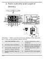
Illustration1: Parts overview and screen displays of the base sta-
tion (1-26) and the wireless sensor (27-33).
1 SNOOZE/DIMMER button 2 Current temperature value
(outdoors)
3 Humidity value (outdoors) 4 Maximum and minimum tem-
perature values (outdoors)
5 Air humidity maximum and
minimum values (indoors)
6 Current temperature value
(indoors)
7 Current humidity value (in-
doors)
8 Symbol for RC clock signal

7 / 32
9 Indoor climate indicator
(shows the quality of the in-
door climate)
10 ALERT button
11 WEATHER button 12 ALARM button
13 Date display 14 DOWN/°C/°F button
15 MODE/SET button 16 AM/PM symbol for 12-hour
time mode
17 Weekday display 18 LO/HI symbol for minimum/
maximum value info
19 Graphical display of the
weather situation
20 Wall mount fixture
21 Battery compartment cover 22 Battery compartment
23 MEMORY button 24 Stand, fold-out
25 RF SEARCH button 26 RESET knob
27 Temperature and humidity
value
28 Wall mount fixture
29 RESET knob 30 °C/°F button
31 Stand, fold-out 32 Battery compartment cover
33 Battery compartment
Scope of delivery:
Base station (A), wireless sensor (B)
Required batteries (not included):
2 pcs. Mignon batteries (1.5V, type AA/LR6) (base station),
2 pcs. micro batteries (1.5V, type AAA/LR03) (wireless
sensor)

8 / 32
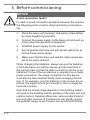
5 Before commissioning
NOTICE
Avoid connection faults!
In order to avoid connection problems between the devices,
the following points must be observed during commission-
ing.
1. Place the base unit (receiver) and sensor (transmitter)
as close together as possible.
2. Connect the power supply to the base unit and wait un-
til the indoor temperature is displayed.
3. Establish power supply for the sensor.
4. Set up/operate the base unit and sensor within the ef-
fective transmission range.
5. Make sure that the base unit and the radio sensor are
set to the same channel.
When changing the batteries, always remove the batteries
in both the base unit and the sensor and reinsert them in
the correct order so that the radio connection can be re-es-
tablished. If one of the two devices is operated via a mains
power connection, the power connection for this device
must also be disconnected briefly when changing the bat-
tery. If, for example, only the batteries in the sensor are re-
placed, the signal cannot be received or can no longer be
received correctly.
Note that the actual range depends on the building materi-
als used in the building and the position of the base unit and
outdoor sensor. External influences (various radio transmit-
ters and other sources of interference) can greatly reduce
the possible range. In such cases, we recommend finding

9 / 32
other locations for both the base unit and the outdoor
sensor. Sometimes a shift of just a few centimetres is
enough!
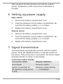
6 Setting up power supply
Base station
1. Remove the battery compartment cover.
2. Insert the batteries into the battery compartment. En-
sure that the battery polarity (+/-) is correct.
3. Replace the battery compartment cover.
Remote sensor
4. Remove the battery compartment cover.
5. Insert the batteries into the battery compartment. En-
sure that the battery polarity (+/-) is correct.
6. Replace the battery compartment cover.
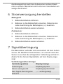
7 Signal transmission
The base station automatically connects with the outdoor
sensor. Press RF SEARCH button to manually search for
the sensor. If the connection is successful, the sensor signal
strength indicator is shown on the display.
Connection status display:
Connection status Display indication
Good signal Receiver symbol
Sensor is searched for Receiver symbol flashes
No signal for a long period
of time
'--.-' is displayed

10 / 32
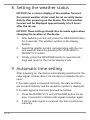
8 Setting the weather status
NOTICE!For a correct display of the weather forecast,
the current weather status must be set correctly imme-
diately after powering on the device. The first weather
forecast will be displayed approximately 6 to 8 hours
after the set-up.
NOTICE!These settings should also be made again when
changing the location of the device.
1. After switching on the unit, press the WEATHER button
for 3 seconds. The weather symbol on the display
flashes.
2. Select the graphic symbol corresponding with the cur-
rent weather status by pressing the UP/ALARM or
DOWN/°C/°F button.
3. Finally, press the WEATHER button to save the set-
tings and return to the normal display mode.
9 Automatic time setting
After powering on, the device automatically searches for the
radio signal. It takes about 3-8 minutes to complete this pro-
cess.
If the radio signal is received correctly, the date and time
are set automatically and the reception symbol is displayed.
If no radio signal is received, proceed as follows:
1. Press the DOWN/°C/°F and UP/ALARM button for ap-
prox. 2 seconds to initiate radio signal reception again.
2. If still no radio signal is received, the time must be set
manually.

11 / 32
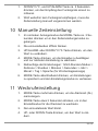
10 Manual time setting
1. In normal display mode, press the MODE button for
about 3 seconds to enter the time settings mode.
2. Digits to be set are flashing.
3. Press UP/ALARM or DOWN/°C/°F button to change the
value.
4. Press the MODE button to confirm and switch to the
next setting.
5. Settings sequence: 12/24-hour mode > Time zone >
Hours > Minutes > Seconds > Year > Month > Day >
Language (for weekday display)
6. Finally, press the MODE button to save the settings
and exit settings mode.
11 Alarm setting
1. Press the MODE key several times to display the alarm
time (AL).
2. Press the MODE button for about 3 seconds to switch
to the setting mode for the corresponding alarm time.
3. The value to be set is flashing.
4. Press UP or DOWN button to change the value.
5. Press the MODE button to confirm and switch to the
next setting.
6. Settings sequence: Hours > Minutes
7. Finally, press the MODE button to save the settings
and exit settings mode.
8. Press the UP/ALARM button to enable the alarm. The
alarm symbol (bell) appears on the display.

12 / 32
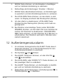
9. To deactivate the alarm, press the ALARM button re-
peatedly until the alarm symbol (bell) is no longer dis-
played.
10. When the alarm sounds, press any key (except
SNOOZE/DIMMER) to disable the alarm until the alarm
time is reached next. Press SNOOZE/DIMMER button
to pause the alarm for 5 minutes. The alarm will be
automatically disabled after 2 minutes.
12 Outdoor temperature alarm
1. In the normal display mode, press the ALERT button
for about 3 seconds to enter the setting mode for out-
door temperature alarm.
2. The symbols und will flash.
3. Press the ALERT button to select the value for or
.
4. Press UP/ALARM or DOWN/°C/°F button to change the
value.
5. Press the ALERT button to confirm and switch to the
next setting.
6. Settings sequence: Highest temperature >> Lowest
temperature
>> Exit
7. Finally, press the ALERT button to save the settings
and return to normal display mode.
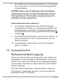
NOTICE!If no setting is made after 30 seconds, the set-
ting mode will be closed automatically. Settings made
up to that point will be saved.
Enabling outdoor temperature alarm

13 / 32
8. In normal display mode, press the ALERT button briefly
several times to enable the desired temperature
alarm(s). Depending on the selection, the symbols
and/or appear individually or together on the display.
9. If the outdoor temperature reaches one of the limit val-
ues, the temperature alarm symbol flashes and a warn-
ing tone sounds.
10. Press any button to stop the temperature alarm.
13 Receiving measurements
automatically
Once the power supply is enabled, the base station will dis-
play the measurement readings for indoors. Readings from
the outdoor sensor will be displayed within 3 minutes after
powering it on.
If no signal is received, proceed as follows:
Press the CH button for about 3 seconds to initate reception
of measurements again.
14 Past 24 hours history data
The base station stores the maximum and minimum temper-
ature and humidity values received from the outdoor sensor
until the next manual reset, but for no longer than 24 hours.
1. In normal display mode, press the MEMORY button to
switch to memory mode. [MEM] appears on the display.
2. Press the MEMORY button several times to also dis-
play the time and date information for the values one
after another.

14 / 32
3. After passing through all stored values, the display
jumps back to the normal display mode. [MEM] is no
longer displayed.
4. When [MEM] is shown on the display, press the
MEMORY button for about 3 seconds to manually clear
all data from the outdoor sensor that has been stored
previously.
NOTICE!After 24 hours, the stored data is automatically
deleted in any case. The deletion of the data cannot be
undone! The station automatically starts recording data
again until the next manual/automatic deletion.
15 EC declaration of conformity
A "Declaration of conformity" in accordance with the
applicable directives and corresponding standards
has been prepared by Bresser GmbH
. The full text of
the EC declaration of conformity is available at the
following Internet address: www.bresser.de/
download/7007330/CE/7007330_CE.pdf
16 UKCA Declaration of Conformity
Bresser GmbH has issued a "Declaration of Con-
formity" in accordance with applicable guidelines and
corresponding standards. The full text of the UKCA
declaration of conformity is available at the following
internet address: www.bresser.de/
download/7007330/UKCA/7007330_UKCA.pdf
Bresser UK Ltd. • Suite 3G, Eden House, Enter-
prise Way, Edenbridge, Kent TN8 6Hf, Great Britain

15 / 32
17 Warranty
The regular warranty period is 5 years and starts on the day
of purchase. For full warranty terms and services, please
visit www.bresser.de/warranty_terms
.
18 Disposal
Dispose of the packaging materials properly, accord-
ing to their type, such as paper or cardboard. Contact
your local waste-disposal service or environmental au-
thority for information on the proper disposal.
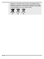
Do not dispose of electronic devices in the household
garbage!
According to the European Directive 2012/19/EU on
Waste Electrical and Electronic Equipment and its
transposition into national law, used electrical equip-
ment must be collected separately and recycled in an
environmentally sound manner.
Batteries and rechargeable batteries must not be dis-
posed of with household waste. You are legally obliged
to return used batteries and accumulators and can re-
turn the batteries after use either in our sales outlet or
in the immediate vicinity (e.g. in the trade or in muni-
cipal collection points) free of charge.
Batteries and accumulators are marked with a crossed-
out dustbin and the chemical symbol of the pollutant,
"Cd" stands for cadmium, "Hg" stands for mercury and
"Pb" stands for lead.

16 / 32
1 Impressum
Bresser GmbH
Gutenbergstr. 2
46414
Rhede
Germany
www.bresser.de
Für etwaige Gewährleistungsansprüche oder Serviceanfra-
gen verweisen wir auf die Informationen zu „Garantie“ und
„Service“ in dieser Dokumentation. Wir bitten um Verständ-
nis, dass direkt an die Hersteller-Anschrift gerichtete Anfra-
gen oder Einsendungen nicht bearbeitet werden können.
Irrtümer und technische Änderungen vorbehalten.
© 2021 Bresser GmbH
Alle Rechte vorbehalten.
Die Reproduktion dieser Dokumentation – auch auszugs-
weise – in irgendeiner Form (z.B. Fotokopie, Druck, etc.) so-
wie die Verwendung und Verbreitung mittels elektronischer
Systeme (z.B. Bilddatei, Website, etc.) ohne eine vorherige
schriftliche Genehmigung des Herstellers ist nicht gestattet.
Die in dieser Dokumentation verwendeten Bezeichnungen
und Markennamen der jeweiligen Firmen sind im Allgemei-
nen in Deutschland, der Europäischen Union und/oder wei-
teren Ländern waren-, marken- und/oder patentrechtlich ge-
schützt.
2 Gültigkeitshinweis
Diese Dokumentation ist gültig für die Produkte mit den
nachfolgend aufgeführten Artikelnummern:

17 / 32
7007330
Anleitungsversion: 0521
Bezeichnung dieser Anleitung:
Manual_7007330_Neomeo-Colour_en-de_BRES-
SER_v052021a
Informationen bei Serviceanfragen stets angeben.
3 Zu dieser Anleitung
HINWEIS
Diese Bedienungsanleitung ist als Teil des Gerätes zu
betrachten!
Lesen Sie vor der Benutzung des Geräts aufmerksam die
Sicherheitshinweise und die Bedienungsanleitung.
Bewahren Sie diese Bedienungsanleitung für die erneute
Verwendung zu einem späteren Zeitpunkt auf. Bei Verkauf
oder Weitergabe des Gerätes ist die Bedienungsanleitung
an jeden nachfolgenden Besitzer/Benutzer des Produkts
weiterzugeben.

18 / 32
4 Teileübersicht und Lieferumfang
17
19
3
7
8
9
10
11
121415
6
2
4
5
13
16
26
25
23
24
20
1
18
27
28
33
29
21
31
32
30
22
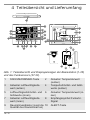
Abb.1: Teileübersicht und Displayanzeigen der Basisstation (1-26)
und des Funksensors (27-33).
1 SNOOZE/DIMMER-Taste 2 Aktueller Temperaturwert
(außen)
3 Aktueller Luftfeuchtigkeits-
wert (außen)
4 Temperturhöchst- und tiefst-
werte (außen)
5 Luftfeuchtigkeitshöchst- und
tiefstwerte (innen)
6 Aktueller Temperaturwert (in-
nen)
7 Aktueller Luftfeuchtigkeits-
wert (innen)
8 Empfangssymbol Funkuhr-
Signal
9 Raumklimaindikator (zeigt die
Qualität des Raumklimas an)
10 ALERT-Taste

19 / 32
11 WEATHER-Taste 12 UP/ALARM-Taste
13 Datumsanzeige 14 DOWN/°C/°F-Taste
15 MODE/SET-Taste 16 AM/PM-Symbol für 12-Stun-
den-Zeitmodus
17 Wochentagsanzeige 18 LO/HI-Symbol für Tiefst-/
Höchstwertinfo
19 Grafische Anzeige der Wet-
terlage
20 Vorrichtung für die Wand-
montage
21 Batteriefachabdeckung 22 Batteriefach
23 MEMORY-Taste 24 Standfuß, ausklappbar
25 RF SEARCH-Taste 26 RESET-Knopf
27 Temperatur- und Luftfeuch-
tigkeitswert
28 Vorrichtung für die Wand-
montage
29 RESET-Knopf 30 °C/°F-Knopf
31 Standfuß, ausklappbar 32 Batteriefachabdeckung
33 Batteriefach
Lieferumfang:
Basisstation (A), Funksensor (B)
Erforderliche Batterien (nicht im Lieferumfang enthal-
ten):
2 Stck. Mignon-Batterien (1.5V, Typ AA/LR6) (Basisstation),
2 Micro-Batterien (1.5V, Typ AAA/LR03) (Funksensor)

20 / 32
5 Vor der Inbetriebnahme
HINWEIS
Vermeidung von Verbindungsstörungen!
Um Verbindungsstörungen zwischen den Geräten zu ver-
meiden, sind die folgenden Punkte bei der Inbetriebnahme
zu beachten.
1. Basisgerät (Empfänger) und Sensor (Sender) so nah
wie möglich nebeneinander stellen/legen.
2. Stromversorgung für das Basisgerät herstellen und
warten bis die Innentemperatur angezeigt wird.
3. Stromversorgung für den Sensor herstellen.
4. Basisgerät und Sensor innerhalb des effektiven Über-
tragungsbereichs aufstellen/betreiben.
5. Sicherstellen, dass Basisgerät und Funksensor auf den
gleichen Kanal eingestellt sind.
Bei einem Batteriewechsel stets die Batterien sowohl im Ba-
sisgerät als auch im Sensor entfernen und in richtiger Rei-
henfolge wieder neu einsetzen, damit die Funkverbindung
erneut aufgebaut werden kann. Wird eines der beiden Ge-
räte über einen Netzstromanschluss betrieben, so muss
auch für dieses bei einem Batteriewechsel kurzzeitig die
Stromverbindung getrennt werden. Werden z.B. nur die Bat-
terien im Sensor ausgetauscht, kann das Signal anschlie-
ßend gar nicht oder nicht mehr korrekt empfangen werden.
Beachten Sie, dass die tatsächliche Reichweite von den je-
weils verwendeten Baumaterialien der Gebäude sowie der
jeweiligen Position der Basiseinheit und des Außensensors
abhängt. Durch externe Einflüsse (diverse Funksender und
andere Störquellen) kann sich die mögliche Reichweite
stark verringern. In solchen Fällen empfehlen wir, sowohl für
Seite wird geladen ...
Seite wird geladen ...
Seite wird geladen ...
Seite wird geladen ...
Seite wird geladen ...
Seite wird geladen ...
Seite wird geladen ...
Seite wird geladen ...
Seite wird geladen ...
Seite wird geladen ...
Seite wird geladen ...
Seite wird geladen ...
-
 1
1
-
 2
2
-
 3
3
-
 4
4
-
 5
5
-
 6
6
-
 7
7
-
 8
8
-
 9
9
-
 10
10
-
 11
11
-
 12
12
-
 13
13
-
 14
14
-
 15
15
-
 16
16
-
 17
17
-
 18
18
-
 19
19
-
 20
20
-
 21
21
-
 22
22
-
 23
23
-
 24
24
-
 25
25
-
 26
26
-
 27
27
-
 28
28
-
 29
29
-
 30
30
-
 31
31
-
 32
32


Bresser 7007330 Bedienungsanleitung
- Kategorie
- Wecker
- Typ
- Bedienungsanleitung
in anderen Sprachen
- English: Bresser 7007330 Owner's manual
Verwandte Artikel
-
Bresser 7000025000000 Bedienungsanleitung
-
Bresser 7004502000000 Bedienungsanleitung
-
-
Bresser Temeo Life H Bedienungsanleitung
-
Bresser WTW Professional Rain Gauge Bedienungsanleitung
-
Bresser 7002533 Bedienungsanleitung
-
-
-
-