METREL EDMD9225 Benutzerhandbuch
- Kategorie
- Messung
- Typ
- Benutzerhandbuch
Dieses Handbuch eignet sich auch für

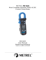
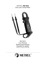
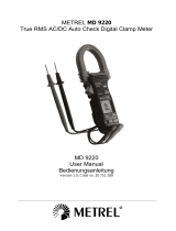
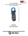
METREL MD 9225
Most Complete Industrial TRMS AC/DC
Current Clamp Meter
MD 9225
User Manual
Bedienungsanleitung
Version 1.0, Code no. 20 752 001

2
Distributor:
METREL d.d.
Ljubljanska cesta 77
1354 Horjul
Slovenia
e-mail: [email protected]
web site: http://www.metrel.si/
Metrel GmbH
Mess und Prüftechnik
Orchideenstrasse 24
90542 Eckental -Brand
Germany
E-mail: [email protected]
Internet: http://www.metrel.de/
Metrel UK
Test & Measurement
Unit 1, Hopton House,
Ripley Drive,
Normanton Industrial Estate,
Normanton,
West Yorkshire
WF6 1QT
Great Britain
E-mail: [email protected]
Internet: http://www.metrel.co.uk/
© 2012 METREL
Mark on your equipment certifies that this equipment meets the requirements of the EC
(European Community) regulations concerning safety and electromagnetic compatibility.
No part of this publication may be reproduced or utilized in any form or by any means
without permission in writing from METREL.

MD 9225 Clamp Meter Series Table of contents / Inhalt
3
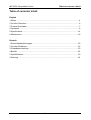
Table of contents/ Inhalt
English
1 Safety ...........................................................................................................................4
2 Cenelec Directives........................................................................................................6
3 Product Description ......................................................................................................7
4 Operation......................................................................................................................8
5 Specifications..............................................................................................................14
6 Maintenance ...............................................................................................................18
Deutsch
1.Sicherheitsbestimmungen ..........................................................................................20
2 Cenelec-Richtlinien.....................................................................................................22
3 Produktbeschreibung..................................................................................................23
4 Betrieb ........................................................................................................................24
5 Spezifikationen ...........................................................................................................30
6 Wartung ......................................................................................................................34

MD 9225 Clamp Meter Series Safety
4
1 Safety
This manual contains information and warnings that must be followed for operating the
instrument safely and maintaining the instrument in a safe operating condition. If the
instrument is used in a manner not specified by the manufacturer, the protection
provided by the instrument may be impaired.
The meter protection rating, against the users, is double insulation per IEC61010-1 2nd
Ed., EN61010-1 2nd Ed., UL61010-1 2nd Ed., CAN/CSA C22.2 No. 61010-1, 2nd Ed.,
IEC61010-2-032, EN61010-2-032, UL61010B-2-032 and CAN/CSA C22.2 No. 61010-2-
032-04
Category CAT III 600V AC & DC.
PER IEC61010 OVERVOLTAGE INSTALLATION CATEGORY
OVERVOLTAGE CATEGORY II
Equipment of OVERVOLTAGE CATEGORY II is energy-consuming equipment to be
supplied from the fixed installation.
Note – Examples include household, office, and laboratory appliances.
OVERVOLTAGE CATEGORY III
Equipment of OVERVOLTAGE CATEGORY III is equipment in fixed installations.
Note – Examples include switches in the fixed installation and some equipment for
industrial use with permanent connection to the fixed installation.
OVERVOLTAGE CATEGORY IV
Equipment of OVERVOLTAGE CATEGORY IV is for use at the origin of the installation.
Note – Examples include electricity meters and primary over-current protection
equipment.
TERMS IN THIS MANUAL
WARNING identifies conditions and actions that could result in serious injury or even
death to the user.
CAUTION identifies conditions and actions that could cause damage or malfunction in
the instrument.
WARNING
To reduce the risk of fire or electric shock, do not expose this product to rain or moisture.
The meter is intended only for indoor use.
To avoid electrical shock hazard, observe the proper safety precautions when working
with voltages above 60 VDC or 30 VAC rms. These voltage levels pose a potential
shock hazard to the user.
Keep your hands/fingers behind the hand/finger barriers (of the meter and the test leads)
that indicate the limits of safe access of the hand-held part during measurement.
Inspect test leads, connectors, and probes for damaged insulation or exposed metal
before using the instrument. If any defects are found, replace them immediately.

MD 9225 Clamp Meter Series Safety
5
This Clamp-on meter is designed to apply around or remove from uninsulated
hazardous live conductors. But still, individual protective equipment must be used if
hazardous live parts in the installation where measurement is to be carried out could be
accessible.
CAUTION
Disconnect the test leads from the test points before changing meter functions.
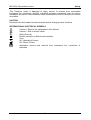
INTERNATIONAL ELECTRICAL SYMBOLS
Caution ! Refer to the explanation in this Manual
Caution ! Risk of electric shock
Earth (Ground)
Double Insulation or Reinforced insulation
Fuse
AC--Alternating Current
DC--Direct Current
Application around and removal from hazardous live conductors is
permitted

MD 9225 Clamp Meter Series Cenelec Directives
6
2 Cenelec Directives
The instruments conform to CENELEC Low-voltage directive 73/23/EEC and
Electromagnetic compatibility directive 89/336/EEC

MD 9225 Clamp Meter Series Product Description
7
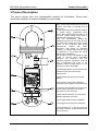
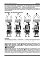
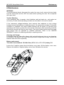
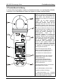
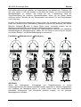
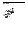
3 Product Description
This user's manual uses only representative model(s) for illustrations. Please refer
specification details for function availability to each model.
1) To reduce the risk of fire or electric
shock, do not expose this product to rain or
moisture. The meter is intended only for
indoor use.
To avoid electrical shock hazard, observe
the proper safety precautions when
working with voltages above 60 VDC or 30
VAC rms. These voltage levels pose a
potential shock hazard to the user.
Keep your hands/fingers behind the
hand/finger barriers (of the meter and the
test leads) that indicate the limits of safe
access of the hand-held part during
measurement. Inspect test leads,
connectors, and probes for damaged
insulation or exposed metal before using
the instrument. If any defects are found,
replace them immediately.
This Clamp-on meter is designed to apply
around or remove from uninsulated
hazardous live conductors. But still,
individual protective equipment must be
used if hazardous live parts in the
installation where measurement is to be
carried out could be accessible.
2) Hand/Finger Barrier to indicate the limits
of safe access of the meter during
measurement
3) Push-buttons for special functions &
features
4) Input Jack for all functions EXCEPT
non-invasive ACA & DCA current functions
5) Common (Ground reference) Input Jack
for all functions EXCEPT non-invasive
ACA & DCA current functions
6) Slide-switch Selector to turn the power
ON/OFF and Select a function
7) 3-3/4 digits 4000 counts LCD display
8) Jaw trigger for opening the clamp jaw
9) DCA direction for + polarity as well as
Jaw center Indicator, at where best ACA &
DCA accuracy is

MD 9225 Clamp Meter Series Operation
8
4 Operation
CAUTION: Before and after hazardous voltage measurements, test the voltage function
on a known source such as line voltage to determine proper meter functioning.
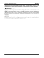
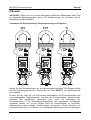
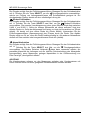
DC Voltage, AC Voltage, Hz Frequency functions
Set slide-switch to Voltage function position. Inputs are made through the test leads
terminals. Press SELECT button momentarily to select DC voltage.
Press the Hz button momentarily to activate Hz Frequency. The Hz trigger level is
determined by the selected function-range from where the Hz function is activated. In
ACV function, activating the Hz function during significant measurements can get the
most appropriate trigger level to avoid electrical noises in most cases. Electrical noise
may cause unstable Hz reading. Activating the Hz function at AC 4.000V range (before
making significant measurements) can get lower trigger level (higher sensitivity). Hz
reading may show zero when the sensitivity is insufficient.
Note: DC 400.0mV range is designed with 1000M: high input impedance for least

MD 9225 Clamp Meter Series Operation
9
current drain in measuring small signals, and can cope better with most commercially
available voltage output transducers/adapters. The non-zero display reading is normal
when the meter inputs are open circuit, which will not affect actual measurement
accuracy. The meter will show close-to-zero readings when the inputs are shorted.
Open input is actually a floating condition, which is not a zero-volt-input condition.
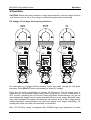
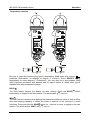
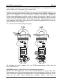
ACA & DCA Current clamp-on function
Inputs are made through the clamp jaws for non-invasive ACA & DCA current
measurements.
CAUTION (Application and removal of the Clamp-on meter)
Press the jaw trigger and clamp the jaws around only one single conductor of a circuit
for load current measurement. Make sure the jaws are completely closed, or else it will
introduce measurement errors. Enclosing more than one conductor of a circuit will result
in differential current measurement (like identifying leakage current). Locate the
conductor(s) at the Jaws center as much as possible to get the best measuring
accuracy. The jaw “+” mark indicates current flow direction on DCA positive readings.
For removal, press the jaw trigger and remove the jaws from the conductor(s).

MD 9225 Clamp Meter Series Operation
10
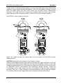
Note: In DCA measurements, hysteresis of the jaws (after measuring high DC currents)
may introduce non-zero residual readings. Relative Zero mode should be used each
time to offset the residual readings, if any, for more accurate measurements.
Adjacent current-carrying devices such as transformers, motors and conductor wires will
affect measurement accuracy. Keep the jaws away from them as much as possible to
minimize influence.
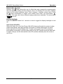
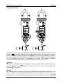
: Resistance, and Continuity functions
CAUTION
Using Resistance, Continuity or Diode function in a live circuit will produce false results
and may damage the instrument. In many cases the suspected component must be
disconnected from the circuit to obtain an accurate measurement reading
Inputs are made through the test leads terminals. Slide-switch on defaults at :. Press
SELECT button momentarily to select Continuity function which is convenient for
checking wiring connections and operation of switches. A continuous beep tone
indicates a complete wire.
Diode test function
Inputs are made through the test leads terminals. Slide-switch on defaults at :.Press
SELECT button momentarily 2 times to select Diode test function. Normal forward
voltage drop (forward biased) for a good silicon diode is between 0.400V to 0.900V. A
reading higher than that indicates a leaky diode (defective). A zero reading indicates a
shorted diode (defective). An OL indicates an open diode (defective). Reverse the test

MD 9225 Clamp Meter Series Operation
11
leads connections (reverse biased) across the diode. The digital display shows OL if the
diode is good. Any other readings indicate the diode is resistive or shorted (defective).
Capacitance function
Inputs are made through the test leads terminals. Slide-switch on defaults at :.Press
SELECT button momentarily 3 times to select Capacitance function. Relative zero
mode can be used to zero out the parasitic capacitance of the leads and the internal
protection circuitry of the meter when measuring low capacitance in the order of Pico
Farad (pF).
CAUTION
Discharge capacitors before making any measurement. Large value capacitors should
be discharged through an appropriate resistance load

MD 9225 Clamp Meter Series Operation
12
Temperature function
Be sure to insert the banana plug type-K temperature bead probe with correct
polarities. Slide-switch on defaults at degree C (Celsius). Press SELECT button
momentarily to select degree F (Fahrenheit). You can also use a plug adapter AMD
9024 (Optional purchase) with banana pins to type-K socket to adapt other type-K
standard mini plug temperature probes.
HOLD
The Hold feature freezes the display for later viewing. Press the HOLD button
momentarily to toggle to the Hold feature. The annunciator “ ” turns on.
MAX
The max feature compares and displays the measured maximum value as fast as 30ms
with auto-ranging capability. It allows the meter to capture in-rush currents in current
functions. Press and hold the MAX button for 1 second or more to toggle to the max
feature. The annunciators “MAX” and “ ” turn on.

MD 9225 Clamp Meter Series Operation
13
Relative Zero mode
Relative Zero mode allows the user to offset the meter consecutive measurements
with the displaying reading as the reference value. The display will now show readings
relative to the stored reference value. That is, display = reading - stored value. Press
the button momentarily to toggle to the relative zero mode. The annunciator “ ”
turns on. The meter also enters manual ranging mode where available. The annunciator
“” turns off.
Display Backlight
Press the SELECT button for 1 second or more to toggle the display backlight on and
off.
Auto Power Off (APO)
When the meter is on, the Auto Power Off (APO) feature will switch the meter to sleep
mode automatically after approximately 30 minutes of neither slide-switch nor push
button operations to extend battery life. To wake up the meter from APO, press any
push-button momentarily or set the slide-switch to the OFF position and then slide back
on again. Always set the slide-switch to the OFF position manually when the meter is
not in use.

MD 9225 Clamp Meter Series Specifications
14
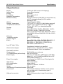
5 Specifications
Display: 3-3/4 digits 4000 counts LCD display(s)
Update Rate: 3 per second nominal
Polarity: Automatic
Low Battery: Below approx. 2.4V
Operating Temperature: 0oC to 40oC
Relative Humidity: Maximum relative humidity 80% for temperature up
to 31oC decreasing linearly to 50% relative
humidity at 40oC
Altitude: Operating below 2000m
Storage Temperature: -20oC to 60oC, < 80% R.H. (with battery removed)
Temperature Coefficient: nominal 0.15 x (specified accuracy)/ oC @(0oC -
18oC or 28oC -40oC), or otherwise specified
Sensing : True RMS
Safety : Meets IEC61010-1 2nd Ed., EN61010-1 2nd Ed.,
UL61010-1 2nd Ed., CAN/CSA C22.2 No.
61010.1-0.92, IEC61010-2-032, EN61010-2-032 &
UL61010B-2-032 and CAN/CSA C22.2 No. 61010-
2-032-04:
Category: III 600 Volts ac & dc.
Transient protection: 6.5kV (1.2/50Ps surge)
Pollution degree: 2
E.M.C.: Meets EN61326-1:2006 (EN55022, EN61000-3-2,
EN61000-3-3, EN61000-4-2, EN61000-4-3,
EN61000-4-4, , EN61000-4-5, EN61000-4-6,
EN61000-4-8, EN61000-4-11)
In an RF field of 3V/m:
Capacitance function is not specified
Other function ranges: Total Accuracy = Specified Accuracy + 50igits
Performance above 3V/m is not specified
Overload Protections:
Clamp-on jaws: DC/AC 400A rms continuous
+ & COM terminals (all functions): 600 VDC/VAC rms
Power Supply: standard 1.5V AAA Size (NEDA 24G or IEC R03)
battery X 2; or 1.5V AAA Size (NEDA 24A or IEC
LR03) alkaline battery X 2
Power Consumption: 11mA typical for ACA/DCA and 2.9mA typical for
other functions
APO Timing: Idle for 30 minutes
APO Consumption: typical 190PA
Dimension: L188mm X W63mm X H40mm
Weight: 218 gm approx
Jaw opening & Conductor diameter: 30mm max
Accessories: Test lead pair, batteries installed, user's manual,
soft carrying pouch, & banana plug type-K
thermocouple
Optional accessories: AMD 9024 banana plug to type-K socket plug
adaptor

MD 9225 Clamp Meter Series Specifications
15
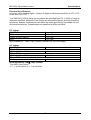
Electrical Specifications
Accuracy is ±(% reading digits + number of digits) or otherwise specified, at 23oC ± 5oC
& less than 75% R.H.
True RMS ACV & ACA clamp-on accuracies are specified from 5% to 100% of range or
otherwise specified. Maximum Crest Factor are as specified below, and with frequency
spectrums, besides fundamentals, fall within the meter specified AC bandwidth for non-
sinusoidal waveforms. Fundamentals are specified at 50Hz and 60Hz.
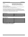
DC Voltage
RANGE Accuracy
400.0 mV 0.3% + 3d
4.000V, 40.00V, 400.0V 0.5% + 3d
600V 1.0% + 4d
Input Impedance : 10M:, 30pF nominal (1000M: for 400.0mV range)
AC Voltage
RANGE Accuracy
50Hz ~ 60Hz
4.000V, 40.00V, 400.0V 1.0% + 4d
60Hz ~ 500Hz
4.000V, 40.00V, 400.0V 1.5% + 4d
50Hz ~ 500Hz
600V 2.0% + 4d
Input Impedance: 10M:, 30pF nominal
True RMS Crest Factor:
< 2 : 1 at full scale & < 4 : 1 at half scale

MD 9225 Clamp Meter Series Specifications
16
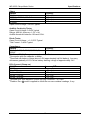
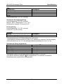
Ohms
RANGE Accuracy
400.0:0.8% + 6d
4.000k:, 40.00k:, 400.0k:0.6% + 4d
4.000M:1.0% + 4d
40.00M:2.0% + 4d
Open Circuit Voltage : 0.4VDC typical
Audible Continuity Tester
Open Circuit Voltage: 0.4VDC typical
Range: 400.0:; Accuracy: 1.5% + 8d
Audible threshold: between 10: and 120:.
Diode Tester
Open Circuit Voltage : < 1.6 VDC Typical
Test Current : 0.4mA Typical
Capacitance
RANGE 1) Accuracy 2) 3)
500.0nF, 5.000PF, 50.00PF, 500.0PF,
3000PF
3.5% + 6d
1)Additional 50.00nF range accuracy is not specified
2)Accuracies with film capacitor or better
3)Specified with battery voltage above 2.8V (approximately half full battery). Accuracy
decreases gradually to 12% at low battery warning voltage of approximately 2.4V
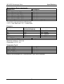
DCA Current (Clamp-on)
RANGE Accuracy 1) 2)
400.0A
0A ~ 50.0A 1.0% + 4d
50.0A ~ 200.0A 1.5% + 5d
200.0A ~ 300.0A 2.0% + 5d
300.0A ~ 400.0A 2.5% + 5d
1)Induced error from adjacent current-carrying conductor: < 0.01A/A
2)Relative Zero mode is applied to offset the non-zero residual readings, if any

MD 9225 Clamp Meter Series Specifications
17
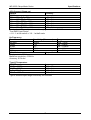
ACA Current (Clamp-on)
RANGE Accuracy1)
400.0A
40Hz ~ 60Hz @ 0 ~ 50A 1.0% + 6d
60Hz ~ 400Hz @ 0 ~ 50A 1.5% + 5d
40Hz ~ 60Hz @ 50A ~ 200A 1.5% + 5d
60Hz ~ 200Hz @ 50A ~ 200A 2.0% + 5d
40Hz ~ 60Hz @ 200A ~ 300A 2.0% + 5d
40Hz ~ 60Hz @ 300A ~ 400A 2.5% + 5d
1)Induced error from adjacent current-carrying conductor: < 0.01A/A
True RMS Crest Factor:
< 1.8 : 1 at full scale & < 3.6 : 1 at half scale
Hz Frequency
Function Sensitivity (Sine wave) Range
400.0mV 350mV 10Hz ~ 1kHz
4.000V 3.2V 5Hz ~ 20kHz
40.00V 25V 5Hz ~ 100kHz
400.0V 100V 5Hz ~ 100kHz
600V 410V 5Hz ~ 5kHz
DCA/ACA Unspecified
Display counts: 5000
Maximum resolution: 0.001Hz
Accuracy: 0.5%+4d
Type-K Temperature
RANGE Accuracy
-20 oC ~ 300 oC 2.0% + 3d
300 oC ~ 537 oC 3.0% + 3d
-4 oF ~ 572 oF 2.0% + 6d
572 oF ~ 1000 oF 3.0% + 6d
Type-K thermocouple range & accuracy not included

MD 9225 Clamp Meter Series Maintenance
18
6 Maintenance
WARNING
To avoid electrical shock, disconnect the meter from any circuit, remove the test leads
from the input jacks and turn OFF the meter before opening the case. Do not operate
with open case.
Trouble Shooting
If the instrument fails to operate, check batteries and test leads etc., and replace as
necessary. Double check operating procedure as described in this user’s manual
If the instrument voltage-resistance input terminal has subjected to high voltage
transient (caused by lightning or switching surge to the system) by accident or abnormal
conditions of operation, the series fusible resistors will be blown off (become high
impedance) like fuses to protect the user and the instrument. Most measuring functions
through this terminal will then be open circuit. The series fusible resistors and the spark
gaps should then be replaced by qualified technician. Refer to the LIMITED
WARRANTY section for obtaining warranty or repairing service.
Cleaning and Storage
Periodically wipe the case with a damp cloth and mild detergent; do not use abrasives
or solvents. If the meter is not to be used for periods of longer than 60 days, remove the
batteries and store them separately
Battery replacement
The meter uses standard 1.5V AAA Size (NEDA 24A or IEC LR03) battery X 2
Loosen the 2 captive screws from the battery cover case. Lift the battery cover case.
Replace the batteries. Replace battery cover case. Re-fasten the screws.

MD 9225 Clamp Meter Series Limited warranty
19
LIMITED WARRANTY
This equipment is warranted against any defects of manufacture or materials.
During the warranty period (2 years), defective parts will be replaced, the manufacturer
reserving the right to repair or replace the product. In the event of the equipment being
returned to the after sale department or to a local agency, the outward transport is
payable by the consignor. For delivery indicate, by means of an enclosed note, as clear
as possible, the reasons for returning it. Any damage caused by shipment using not
original packing will be charged in any case to the consignor.
The manufacturer will not be responsible for any damage to persons or things.
The warranty is not valid in the following cases:
x Accessories and battery are not included in warranty.
x Repairs following unsuitable use of the equipment.
x Repairs necessitated by attempts to repair by a person not approved by the
manufacturer.
x Modification of the equipment without the explicit authorisation of the manufacturer.
x Adaptation to a specific application not provided for in the specifications of the
equipment or the user manual.
x Damage after a drop, a shock or flooding.
The contents of this manual must not be reproduced in any form whatsoever without the
consent of the manufacturer.
Service
The life span of the equipment is 7 years. If the equipment should not work properly,
before the service, test the battery conditions, the test leads, etc., and change them if
necessary.
If the equipment still does not work check if your operating procedure agrees with the
latter described in this manual.
In the event of returning the equipment it must be re-sent to the after-sales service of
the local Metrel distributor, the outward transport is payable by customer. The delivery
must be agreed in advance with consignee. For delivery indicate, by means of an
enclosed note, as clear as possible, the reasons for returning it. Use only the original
packing. Any damage caused by delivery with NO original packing will be charged in
any case to the consignor.
THIS WARRANTY IS EXCLUSIVE AND IS IN LIEU OF ALL OTHER WARRANTIES,
EXPRESSED OR IMPLIED, INCLUDING BUT NOT LIMITED TO ANY IMPLIED
WARRANTY OR MERCHANTABILITY OR FITNESS FOR A PARTICULAR PURPOSE
OR USE. METREL WILL NOT BE LIABLE FOR ANY SPECIAL, INDIRECT,
INCIDENTAL OR CONSEQUENTIAL DAMAGES.
PRINTED ON RECYCLABLE PAPER, PLEASE RECYCLE

MD 9225 Stromzange Serie Sicherheitsbestimmungen
20
1.Sicherheitsbestimmungen
Dieses Handbuch weist Informationen und Warnhinweise aus, die für einen sicheren
Betrieb des Messgeräts und sichere Betriebsbedingungen beachtet werden müssen.
Wenn das Gerät nicht wie vom Hersteller vorgeschrieben verwendet wird, kann der
Schutz, den das Messgerät während des Betriebs bietet, nicht aufrechterhalten werden.
Die Schutzkategorien für dieses Gerät werden mit Doppelisolierung gemäß IEC61010-1 2.
Ausgabe, EN61010-1 2. Ausgabe, UL61010-1 2. Ausgabe, CAN/CSA C22.2 Nr. 61010-1, 2.
Ausgabe, IEC61010-2-032, EN61010-2-032, UL61010B-2-032 und CAN/CSA C22.2 Nr.
61010-2-032-04 angegeben.
Kategorie CAT III 600V AC und DC.
GEMÄß IEC61010 ÜBERSPANNUNGSINSTALLATIONEN
ÜBERSPANNUNGSKATEGORIE II
Geräte nach ÜBERSPANNUNGSKATEGORIE II sind energieverbrauchende Geräte,
die von festen Installationen gespeist werden müssen.
Hinweis – Beispiele sind: Haushalt, Büro und Laboranwendungen.
ÜBERSPANNUNGSKATEGORIE III
Geräte nach ÜBERSPANNUNGSKATEGORIE III sind Geräte in festen Installationen.
Hinweis – Beispiele sind Schalter in festen Installationen und einige Anlagen im
Industriegebrauch mit permanentem Anschluss an die feste Installation.
ÜBERSPANNUNGSKATEGORIE IV
Geräte nach ÜBERSPANNUNGSKATEGORIE IV sind Geräte am Anschlusspunkt der
Installation. Hinweis – Beispiele sind Strommessgeräte und primäre
Überspannungsschutzgeräte.
Bezeichnungen in diesem Handbuch
WARNUNG bezeichnet Bedingungen und Handlungen, die zur schweren Verletzungen
oder gar Tod des Benutzers führen können.
ACHTUNG bezeichnet die Bedingungen und Handlungen, die zu Schäden oder
Fehlfunktionen des Messgeräts führen können.
WARNUNG
Um die Gefahr vor Feuer oder elektrischen Schlägen zu reduzieren, sollte dieses
Produkt nicht im Regen oder bei Feuchtigkeit verwendet werden. Das Messgerät ist
ausschließlich für den Gebrauch in Innenräumen ausgelegt.
Vermeiden Sie die Gefahr elektrischer Schläge, indem Sie die
Sicherheitsbestimmungen beachten, sollten Sie bei Spannungen über 60 V DC bzw.
30 V AC (Effektivwerte) arbeiten. Diese Spannungen stellen eine erhöhte Gefahr für
den Benutzer dar.
Halten Sie Ihre Hände und Finger hinter dem Hand-/Fingerschutz (des Testgeräts und
der Prüfkabel), diese stellen die Grenze des Bereichs der sicheren Handhabung von
Seite wird geladen ...
Seite wird geladen ...
Seite wird geladen ...
Seite wird geladen ...
Seite wird geladen ...
Seite wird geladen ...
Seite wird geladen ...
Seite wird geladen ...
Seite wird geladen ...
Seite wird geladen ...
Seite wird geladen ...
Seite wird geladen ...
Seite wird geladen ...
Seite wird geladen ...
Seite wird geladen ...
Seite wird geladen ...
Seite wird geladen ...
Seite wird geladen ...
Seite wird geladen ...
Seite wird geladen ...
-
 1
1
-
 2
2
-
 3
3
-
 4
4
-
 5
5
-
 6
6
-
 7
7
-
 8
8
-
 9
9
-
 10
10
-
 11
11
-
 12
12
-
 13
13
-
 14
14
-
 15
15
-
 16
16
-
 17
17
-
 18
18
-
 19
19
-
 20
20
-
 21
21
-
 22
22
-
 23
23
-
 24
24
-
 25
25
-
 26
26
-
 27
27
-
 28
28
-
 29
29
-
 30
30
-
 31
31
-
 32
32
-
 33
33
-
 34
34
-
 35
35
-
 36
36
-
 37
37
-
 38
38
-
 39
39
-
 40
40


METREL EDMD9225 Benutzerhandbuch
- Kategorie
- Messung
- Typ
- Benutzerhandbuch
- Dieses Handbuch eignet sich auch für
in anderen Sprachen
- English: METREL EDMD9225 User manual