Asco Series 435 Cylinders CIX-DM Bedienungsanleitung
- Typ
- Bedienungsanleitung

Sachets de pièces de rechange
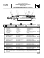
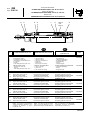
VERINS ANTICORROSION "CIX" Ø 32 à 80 mm
Spare parts kits for
ANTI-CORROSIVE CYLINDERS "CIX" Ø 32 to 80 mm
Ersatzteilliste
KORROSIONSBESTÄNDIGE ZYLINDER "CIX" Ø 32 bis 80 mm
Series
Baureihe
435
Type: CIX-DM
(383 45 11)
PR-P258a
Rep.
DESIGNATION du sachet DESIGNATION of kit
BEZEICHNUNG
der Ersatzteilpackung
CODE
FR
GB
DE
SET OF WEARING PARTS . . . . . . . . .
- 2 Lip seals
- 1 Rod seal
- 2 Cushioning seals
- 1 Wear ring
- 1 O-ring
- 1 Rod seal clip
VERSCHLEISSTEILE . . . . . . . . . . . . . .
- 2 Lippendichtungen
- 1 Kolbenstangendichtung
- 2 Dämpfungsdichtungen
- 1 Führungsring
- 1 O-Ring
- 1 Seegerring
1-6
978 02 130
978 02 131
978 02 132
978 02 133
1
2
3
4
5
6
ENSEMBLE D'USURE . . . . . . . . . . . . .
- 2 Joints à lèvres
- 1 Joint de tige
- 2 Joints d'amortis
- 1 Segment
- 1 Joint torique
- 1 Clip de joint de tige
3
5
3
1
246
Aimant
Magnet
2-5-6
NOTA: Pour obtenir un fonctionnement
optimal en environnement alimentaire, il
est recommandé d'utiliser la graisse
Polylub GA 352P.
NOTE: For optimal operation in a
food processing environment we recom-
mend using Polylub GA 352P grease.
ANMERKUNG: Ein optimales
Funktionieren
im Naherungsmittelbereich wird durch die Ver-
wendung des Schmiermittels Polylub GA 352P
erreicht
NS
ROD SEAL ONLY . . . . . . . . . . . . . . . . .
- 1 Rod seal
- 1 O-ring
- 1 Rod seal clip
KOLBENSTANGENDICHTUNG ALLEIN
- 1 Kolbenstangendichtung
- 1 O-Ring
- 1 Seegerring
2-5-6
2-5-6
2-5-6
978 02 184
978 02 185
978 02 186
978 02 187
2
5
6
ENSEMBLE D'USURE . . . . . . . . . . . . .
Nomenclature dito Ø 32 mm
JOINT DE TIGE SEUL . . . . . . . . . . . . .
Nomenclature dito Ø 32 mm
978 02 188
VERIN Ø 32 mm
CYLINDER Ø 32 mm
VERIN Ø 32 mm
JOINT DE TIGE SEUL . . . . . . . . . . . . .
- 1 Joint de tige
- 1 Joint torique
- 1 Clip de joint de tige
VERIN Ø 40 mm
SET OF WEARING PARTS . . . . . . . . .
Same description as Ø 32 mm
ROD SEAL ONLY . . . . . . . . . . . . . . . . .
Same description as Ø 32 mm
VERIN Ø 50 mm
VERSCHLEISSTEILE . . . . . . . . . . . . . .
Teilebezeichnung wie Ø 32 mm
KOLBENSTANGENDICHTUNG ALLEIN
Teilebezeichnung wie Ø 32 mm
CYLINDER Ø 40 mm
ZYLINDER
Ø 40 mm
CYLINDER Ø 50 mm
ZYLINDER
Ø 50 mm
ENSEMBLE D'USURE . . . . . . . . . . . . .
Nomenclature dito Ø 32 mm
JOINT DE TIGE SEUL . . . . . . . . . . . . .
Nomenclature dito Ø 32 mm
SET OF WEARING PARTS . . . . . . . . .
Same description as Ø 32 mm
ROD SEAL ONLY . . . . . . . . . . . . . . . . .
Same description as Ø 32 mm
VERSCHLEISSTEILE . . . . . . . . . . . . . .
Teilebezeichnung wie Ø 32 mm
KOLBENSTANGENDICHTUNG ALLEIN
Teilebezeichnung wie Ø 32 mm
VERIN Ø 63 mm
CYLINDER Ø 63 mm
ZYLINDER
Ø 63 mm
978 02 134
ENSEMBLE D'USURE . . . . . . . . . . . . .
Nomenclature dito Ø 32 mm
JOINT DE TIGE SEUL . . . . . . . . . . . . .
Nomenclature dito Ø 32 mm
SET OF WEARING PARTS . . . . . . . . .
Same description as Ø 32 mm
ROD SEAL ONLY . . . . . . . . . . . . . . . . .
Same description as Ø 32 mm
VERSCHLEISSTEILE . . . . . . . . . . . . . .
Teilebezeichnung wie Ø 32 mm
KOLBENSTANGENDICHTUNG ALLEIN
Teilebezeichnung wie Ø 32 mm
VERIN Ø 80 mm
CYLINDER Ø 80 mm
ZYLINDER
Ø 80 mm
ENSEMBLE D'USURE . . . . . . . . . . . . .
Nomenclature dito Ø 32 mm
JOINT DE TIGE SEUL . . . . . . . . . . . . .
Nomenclature dito Ø 32 mm
SET OF WEARING PARTS . . . . . . . . .
Same description as Ø 32 mm
ROD SEAL ONLY . . . . . . . . . . . . . . . . .
Same description as Ø 32 mm
VERSCHLEISSTEILE . . . . . . . . . . . . . .
Teilebezeichnung wie Ø 32 mm
KOLBENSTANGENDICHTUNG ALLEIN
Teilebezeichnung wie Ø 32 mm
1-6
1-6
1-6

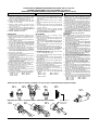
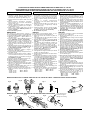
PROCEDURE DE DEMONTAGE-REMONTAGE VERINS CIX Ø 32 à 80 mm
ASSEMBLY/DISASSEMBLY OF CIX CYLINDER Ø 32 to 80 mm
WARTUNGS- UND MONTAGEANLEITUNG FÜR CIX-ZYLINDER Ø 32 bis 80 mm
DEMONTAGE
DEMONTAGE
DISASSEMBLY
1- Dévisser le fond avant en exercant un couple
de rotation à l'aide de deux raccords banjo serrés
dans les orifices d'alimentation (fig. H).
2- Sortir l'ensemble tige/piston du tube de vérin
3- Bloquer l'ensemble tige/piston à l'aide des plats
existant en tête de tige.
4- Retirer les joints à lèvres (1), le joint (5) avec
précaution, ainsi que le segment (4), le clip (6)
et les joints (2) (3)
5- Nettoyer la tige, le piston, l'intérieur du tube et
les emplacements des joints (ne pas utiliser de
produits corrosifs ni solvants)
6- Ne pas démonter le piston
REASSEMBLY
Pour obtenir un fonctionnement optimal, il est re-
commandé d'utiliser la graisse Polylub GA 352 P
1- Retirer de la pochette de rechange les joints à
lèvres (1).
2- Enduire légèrement de graisse les joints à lèvres
et les gorges du piston.
3-
Placer le joint à lèvre dans la gorge d'un côté
du piston (fig.A). Respecter le sens de montage
4- A l'aide d'un outil rond, sans aspérité, terminer
la mise en place du joint en effectuant un
mouvement circulaire. (fig. B)
5-
Controler le positionnement correct du joint (fig. C)
6-
Retourner l'ensemble tige/piston et monter le
2eme joint en répétant les phases 3,4,5. Respec-
ter les sens de montage des lèvres (voir fig. D)
7- Remonter le segment (4)
8- Enduire légèrement de graisse l'intérieur et l'en-
trée du tube et les joints à lévres.
9- Placer le piston en biais dans la partie inférieure
du cylindre (fig. E)
10
-Introduire progressivement le joint à lèvre, à
l'aide d'un outil plat, sans aspérité et en effec-
tuant un mouvement circulaire de la tige (fig. F).
Ne pas utiliser de tournevis
11
-
Enduire de graisse le pourtour central du piston (❉)
12
-
Pousser le piston dans le cylindre (fig. G)
13-
Enduire légèrement de graisse les gorges du
fond avant et les joints (2) (3) (5)
14
-Remonter le joint de tige (2), le joint (5), le joint
d'amorti (3) ainsi que le clip (6)
15-
Protéger l'embout fileté de la tige pour éviter de
détériorer le joint (2)
16
-Visser le fond avant dans le tube (jusqu'à la butée
mécanique), couple de serrage recommandé:
- Ø 32 : 15 N.m - Ø 63 : 160 N.m
- Ø 40 : 25 N.m - Ø 80 : 240 N.m
- Ø 50 : 50 N.m
1-Drehen Sie das vordere Endstück ab unter
Zuhilfenahme der beiden Banjo-Verschraubun-
gen, die sich in den Versorgungsanschlüssen
befinden (Abb. H).
2- Nehmen Sie die Einheit bestehend aus Kolben-
stange und Kolben aus dem Zylinderrohr heraus.
3-
Blockieren Sie die Einheit aus Kolbenstange und Kolben
an den Schlüsselflächen am Kopf der Kolbenstange.
4- Entfernen Sie vorsichtig die Lippendichtungen
(1), den O-Ring (5) den Führungsring (4), den
Seegerring (6) sowie die Dichtungen (2) und (3)
5- Reinigen Sie die Kolbenstange, den Kolben, das
Innere des Zylinderrohrs und die Dichtungsnuten
(ätzende Mittel oder Lösemittel sind nicht zu
verwenden).
6- Demontieren Sie nicht den Kolben.
Ein optimales Funktionieren wird durch Verwendung
des Schmiermittels Polylub GA 352P erreicht
1- Nehmen Sie die Lippendichtungen (3) aus der
Ersatzteilpackung.
2- Schmieren Sie die Lippendichtungen und die
Kolbenringnuten leicht ein.
3- Legen Sie die Lippendichtung auf einer Seite
des Kolbens (Abb.A) in die Nut ein. Beachten
Sie die Montagerichtung.
4- Setzen Sie die Lippendichtung unter Zuhilfenah-
me eines glatten Werkzeugs mit einer drehenden
Bewegung ein (Abb.B).
5-
Überprüfen Sie die richtige Lage der Dichtung (Abb.C).
6- Drehen Sie die Einheit aus Kolbenstange und
Kolben um und legen Sie die 2. Dichtung unter
Wiederholung der Punkte 3,4,5 ein. Beachten
Sie die Montagerichtung der Lippen ( Abb.D).
7- Setzen Sie den Führungsring (4) ein
8.- Schmieren Sie das Innere und den Eingang des
Rohres sowie die Lippendichtungen leicht ein.
9- Setzen Sie den Kolben schräg in den unteren Teil
des Zylinders (Abb. E) ein.
10
-Schieben Sie die Lippendichtung unter Zuhilfe-
nahme eines glatten Werkzeuges mit einer
drehenden Bewegung in den Zylinder (Abb. F).
Verwenden Sie keinen Schraubendreher.
11-Schmieren Sie den Umfang des Mittelteils des
Kolbens ein (❉).
12-
Schieben Sie den Kolben in den Zylinder (Abb. G).
13-
Schmieren Sie die Nuten am vorderen Endstück
und die Dichtungen (2), (3) und (5)
14
-Setzen Sie die Kolbenstangendichtung (2), den
O-Ring (5), und die Dämpfungsdichtung (3) ein
und befestigen Sie den Seegerring (6)
15-
Schützen Sie das Gewinde am Kolbenstangen-
ende, um eine Beschädigung der Dichtung (2) zu
vermeiden
16
-Schrauben Sie das vordere Endstück wieder in
das Rohr ein (bis zum mechanischen Anschlag)
unter Verwendung der folgenden Drehmomente:
- Ø 32 : 15 N.m - Ø 63 : 160 N.m
- Ø 40 : 25 N.m - Ø 80 : 240 N.m
- Ø 50 : 50 N.m
MONTAGE
REMONTAGE
1- Twist off the front cover with the help of the two
banjo-type connections tightened into the supply
ports (fig. H).
2- Remove the rod/piston unit from the cylinder
tube.
3- Block the rod/piston unit at the flats on the rod
head.
4- Carefully remove the lip seals (1), the O-ring (5)
the wear ring (4), the rod seal clip (6) and the
seals (2) and (3)
5- Clean the rod, the piston, the inside of the tube
and the grooves of the seals (do not use
corrosives agents or solvents).
6- Do not disassemble the piston.
Fig. E
Abb. E
MONTAGE DU PISTON / PISTON ASSEMBLY / MONTAGE DES KOLBENS
MONTAGE DES JOINTS A LEVRES / ASSEMBLY OF THE LIP SEALS / MONTAGE DER LIPPENDICHTUNGEN
❉
For best results, we recommend using
Polylub GA 352 P grease
1-
Remove the lip seals from the spare parts bag (3).
2- Coat the lip seals and the piston ring grooves
lightly with grease.
3-
Place the lip seal on one side of the piston into the
groove (fig. A). Observe the mounting direc-
tion.
4- Insert the lip seal with a circular movement using
a flat tool (fig B).
5- Check the correct position of the seal (fig. C).
6- Turn the rod/piston unit around and assemble the
2nd seal by repeating points 3,4,5. Observe the
mounting direction of the lips (see fig.D).
7- Install the wear ring (4)
8- Coat the inside of the tube and its entry as well as
the lip seals lightly with grease.
9- Place the piston diagonally into the bottom part of
the cylinder (fig. E).
10
-Push the lip seal with a circular movement into
the rod using a flat tool (fig. F). Do not use a
screwdriver.
11-Grease the circumference of the middle part of
the piston (❉)
12
-Place the piston back into the cylinder (fig. G).
13-
Coat the grooves on the front cover and the seals
(2), (3) and (5) lightly with grease
14
-Insert the rod seal (2), the O-ring (5), the cushion-
ing seal (3) and install the rod seal clip (6)
15-
Protect the threaded and of the rod to avoid
damaging the seal (2)
16
-Screw the front cover into the tube (up to the
mechanical stop), with the following tightening
torques:
- Ø 32 : 15 N.m - Ø 63 : 160 N.m
- Ø 40 : 25 N.m - Ø 80 : 240 N.m
- Ø 50 : 50 N.m
Fig. H
Abb. H
ENSEMBLE D'USURE SET OF WEARING PARTS
VERSCHLEISSTEILE
Fig. F
Abb. F
Fig. G
Abb. G
Fig. C
Abb. C
Fig. B
Abb. B
Fig. A
Abb. A
Fig. D
Abb. D
Dépôt de graisse
Grease store
Fettkammer

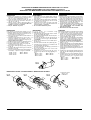
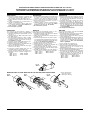
PROCEDURE DE DEMONTAGE-REMONTAGE VERINS CIX Ø 32 à 80 mm
ASSEMBLY/DISASSEMBLY OF CIX CYLINDER Ø 32 to 80 mm
WARTUNGS- UND MONTAGEANLEITUNG FÜR CIX-ZYLINDER Ø 32 bis 80 mm
DEMONTAGE
DEMONTAGE
DISASSEMBLY
1- Dévisser le fond avant en exerçant un couple
de rotation à l'aide de deux raccords banjo serrés
dans les orifices d'alimentation (fig. H).
2- Sortir l'ensemble tige/piston du tube de vérin
3- Retirer le joint (5) avec précaution, ainsi que le
clip (6) et le joint (2)
4- Nettoyer la tige, le piston, l'intérieur du tube et
les emplacements des joints (ne pas utiliser de
produits corrosifs ni solvants)
5- Ne pas démonter le piston
REASSEMBLY
Pour obtenir un fonctionnement optimal, il est re-
commandé d'utiliser la graisse Polylub GA 352 P
1- Enduire légèrement de graisse l'intérieur et l'en-
trée du tube et les joints à lèvres.
2- Placer le piston en biais dans la partie inférieure
du cylindre (fig. E)
3
- Introduire progressivement le joint à lèvre, à
l'aide d'un outil plat, sans aspérité et en effec-
tuant un mouvement circulaire de la tige (fig. F).
Ne pas utiliser de tournevis
4
-
Enduire de graisse le pourtour central du piston (❉)
5
-
Pousser le piston dans le cylindre (fig. G)
6-
Enduire légèrement de graisse les gorges du
fond avant et les joints (2) (5)
7
- Remonter le joint de tige (2), le joint (5), ainsi que
le clip (6).
8-
Protéger l'embout fileté de la tige pour éviter de
détériorer le joint (2)
9
- Visser le fond avant dans le tube (jusqu'à la butée
mécanique), couple de serrage recommandé:
- Ø 32 : 15 N.m - Ø 63 : 160 N.m
- Ø 40 : 25 N.m - Ø 80 : 240 N.m
- Ø 50 : 50 N.m
1-
Drehen Sie das vordere Endstück ab unter Zuhilfe-
nahme der beiden Banjo-Verschraubungen, die sich
in den Versorgungsanschlüssen befinden (Abb. H).
2- Nehmen Sie die Einheit bestehend aus Kolben-
stange und Kolben aus dem Zylinderrohr heraus.
3- Entfernen Sie vorsichtig die O-Ring (5), den
Seegerring (6) sowie die Dichtung (2)
4- Reinigen Sie die Kolbenstange, den Kolben, das
Innere des Zylinderrohrs und die Dichtungs-
nuten (ätzende Mittel oder Lösemittel sind
nicht zu verwenden).
5- Demontieren Sie nicht den Kolben.
Ein optimales Funktionieren wird durch Verwendung
des Schmiermittels Polylub GA 352P erreicht
1.- Schmieren Sie das Innere und den Eingang des
Rohres sowie die Lippendichtungen leicht ein.
2- Setzen Sie den Kolben schräg in den unteren
Teil des Zylinders (Abb. E) ein.
3- Schieben Sie die Lippendichtung unter Zuhilfe-
nahme eines glatten Werkzeuges mit einer
drehenden Bewegung in den Zylinder (Abb. F).
Verwenden Sie keinen Schraubendreher.
4- Schmieren Sie den Umfang des Mittelteils des
Kolbens ein (❉).
5-
Schieben Sie den Kolben in den Zylinder (Abb. G).
6-
Schmieren Sie die Nuten am vorderen Endstück
und die Dichtungen (2) und (5) leicht ein
7
- Setzen Sie die Kolbenstangendichtung (2), und
den O-Ring (5)ein und befestigen Sie den See-
gerring (6).
8-
Schützen Sie das Gewinde am Kolbenstangen-
ende, um eine Beschädigung der Dichtung (2) zu
vermeiden
9
- Schrauben Sie das vordere Endstück wieder in
das Rohr ein (bis zum mechanischen Anschlag)
unter Verwendung der folgenden Dreh-
momente:
- Ø 32 : 15 N.m - Ø 63 : 160 N.m
- Ø 40 : 25 N.m - Ø 80 : 240 N.m
- Ø 50 : 50 N.m
MONTAGEREMONTAGE
1- Twist off the front cover with the help of the two
banjo-type connections tightened into the supply
ports (fig. H).
2-
Remove the rod/piston unit from the cylinder tube.
3- Carefully remove the O-ring (5), the rod seal clip
(6) and the rod seal (2)
4- Clean the rod, the piston, the inside of the tube
and the grooves of the seals
(
do not use cor-
rosives agents or solvents
).
5- Do not disassemble the piston.
Fig. E
Abb. E
Fig. F
Abb. F
MONTAGE DU PISTON / PISTON ASSEMBLY / MONTAGE DES KOLBENS
Fig. G
Abb. G
Dépôt de graisse
Grease store
Fettkammer
For best results, we recommend using
Polylub GA 352 P grease
1- Coat the inside of the tube and its entry as well as
the lip seals lightly with grease.
2- Place the piston diagonally into the bottom part of
the cylinder (fig. E).
3- Push the lip seal with a circular movement into
the rod using a flat tool (fig. F). Do not use a
screwdriver.
4- Grease the circumference of the middle part of
the piston (❉)
5- Place the piston back into the cylinder (fig. G).
6-
Coat the grooves on the front cover and the seals
(2) and (5) lightly with grease
7
- Insert the rod seal (2), the O-ring (5), and install
the rod seal clip (6).
8-
Protect the threaded end of the rod to avoid
damaging the seal (2)
9
- Screw the front cover into the tube (up to me-
chanical stop) with the following tightening tor-
ques:
- Ø 32 : 15 N.m - Ø 63 : 160 N.m
- Ø 40 : 25 N.m - Ø 80 : 240 N.m
- Ø 50 : 50 N.m
Fig. H
Abb. H
❉
JOINT DE TIGE SEUL
ROD SEAL ONLY KOLBENSTANGENDICHTUNG ALLEIN
Seite wird geladen ...
Seite wird geladen ...
Seite wird geladen ...
-
 1
1
-
 2
2
-
 3
3
-
 4
4
-
 5
5
-
 6
6


Asco Series 435 Cylinders CIX-DM Bedienungsanleitung
- Typ
- Bedienungsanleitung
in anderen Sprachen
- English: Asco Series 435 Cylinders CIX-DM Owner's manual
- français: Asco Series 435 Cylinders CIX-DM Le manuel du propriétaire
- español: Asco Series 435 Cylinders CIX-DM El manual del propietario
- italiano: Asco Series 435 Cylinders CIX-DM Manuale del proprietario
- Nederlands: Asco Series 435 Cylinders CIX-DM de handleiding
Verwandte Artikel
-
Asco Series 436 437 Trinorm Cylinder PIS PCN 100-200 mm Bedienungsanleitung
-
Asco series-435-cylinders-iso Bedienungsanleitung
-
-
-
-
-
-
-
-