Asco Series 442 449 Short Stroke Cylinder Type PEC KN Bedienungsanleitung
- Typ
- Bedienungsanleitung

Sachets de pièces de rechange
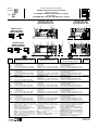
VERINS TYPE PEC ET KN Ø 32 à 100 mm
Spare parts kits for
CYLINDERS TYPES PEC AND KN Ø 32 to 100 mm
Ersatzteilliste
ZYLINDER DES TYPS PEC UND KN Ø 32 bis 100 mm
Series
Baureihe
449
442
Type: PEC
KN
(383 45 58)
PR-P227-1b
Rep.
DESIGNATION du sachet DESIGNATION of kit
BEZEICHNUNG
der Ersatzteilpackung
CODE
FR
GB
DE
978 02 337
1
2
3
4
VERIN Ø 32 mm . . . . . . . . . . . . . . . . . . .
- 2 Joints de tige
- 2 Joints à lèvres
- 2
Joints tube/fond Ø int. 31,2x1 (PEC)
- 2
Joints corps/fond Ø int. 28,3x1,8 (KN)
CYLINDER Ø 32 mm. . . . . . . . . . . . . . . .
- 2 Rod seals
- 2 Lip seals
-
2 O-rings tube/cover Ø int. 31,2x1 (PEC)
-
2 O-rings body/cover Ø int. 28,3x1,8 (KN)
ZYLINDER
Ø 32 mm. . . . . . . . . . . . . . . .
- 2 Kolbenstangendichtungen
- 2 Lippendichtungen
-
2 Dichtungen Rohr/Endstück Ø int. 31,2x1
-
2 Dichtungen Gehaüse/Endstück Ø int. 28,3x1,8
VERIN Ø 40 mm. . . . . . . . . . . . . . . . . . .
- 2 Joints de tige
- 2 Joints à lèvres
- 2
Joints tube/fond Ø int. 39,2x1 (PEC)
- 2
Joints corps/fond Ø int. 37,8x1,8 (KN)
CYLINDER Ø 40 mm. . . . . . . . . . . . . . . .
- 2 Rod seals
- 2 Lip seals
- 2 O-rings
tube/cover
Ø int. 39,2x1 (PEC)
-
2 O-rings body/cover Ø int. 37,8x1,8 (KN)
ZYLINDER
Ø 40 mm. . . . . . . . . . . . . . . .
- 2 Kolbenstangendichtungen
- 2 Lippendichtungen
-
2 Dichtungen Rohr/Endstück Ø int. 39,2x1
-
2 Dichtungen Gehaüse/Endstück Ø int.37,8x1,8
1
2
3
4
VERIN Ø 50 mm. . . . . . . . . . . . . . . . . . .
- 2 Joints de tige
- 2 Joints à lèvres
- 2
Joints tube/fond Ø int. 49x1 (PEC)
- 2
Joints corps/fond Ø int. 47,4x1,8 (KN)
CYLINDER Ø 50 mm. . . . . . . . . . . . . . . .
- 2 Rod seals
- 2 Lip seals
- 2 O-rings
tube/cover
Ø int. 49x1 (PEC)
-
2 O-rings body/cover Ø int. 47,4x1,8 (KN)
ZYLINDER
Ø 50 mm. . . . . . . . . . . . . . . .
- 2 Kolbenstangendichtungen
- 2 Lippendichtungen
-
2 Dichtungen Rohr/Endstück Ø int. 49x1
-
2 Dichtungen Gehaüse/Endstück Ø int. 47,4x1,8
1
2
3
4
978 02 338
978 02 339
VERIN Ø 63 mm. . . . . . . . . . . . . . . . . . .
- 2 Joints de tige
- 2 Joints à lèvres
- 2
Joints tube/fond Ø int. 62x1 (PEC)
- 2
Joints corps/fond Ø int. 60x1,8 (KN)
CYLINDER Ø 63 mm. . . . . . . . . . . . . . . .
- 2 Rod seals
- 2 Lip seals
- 2 O-rings
tube/cover
Ø int. 62x1 (PEC)
- 2 O-rings
body/cover
Ø int. 60x1,8 (KN)
ZYLINDER
Ø 63 mm. . . . . . . . . . . . . . . .
- 2 Kolbenstangendichtungen
- 2 Lippendichtungen
-
2 Dichtungen Rohr/Endstück Ø int. 62x1
-
2 Dichtungen Gehaüse/Endstück Ø int. 60x1,8
1
2
3
4
VERIN Ø 80 mm. . . . . . . . . . . . . . . . . . .
- 2 Joints de tige
- 2 Joints à lèvres
- 2
Joints tube/fond Ø int. 77x1,5 (PEC)
- 2
Joints corps/fond Ø int. 80x2 (KN)
CYLINDER Ø 80 mm. . . . . . . . . . . . . . . .
- 2 Rod seals
- 2 Lip seals
- 2 O-rings
tube/cover
Ø int. 77x1,5 (PEC)
- 2 O-rings
body/cover
Ø int. 80x2 (KN)
ZYLINDER
Ø 80 mm. . . . . . . . . . . . . . . .
- 2 Kolbenstangendichtungen
- 2 Lippendichtungen
-
2 Dichtungen Rohr/Endstück Ø int. 77x1,5
-
2 Dichtungen Gehaüse/Endstück Ø int. 80x2
1
2
3
4
978 02 340
978 02 341
VERIN Ø 100 mm. . . . . . . . . . . . . . . . . . .
- 2 Joints de tige
- 2 Joints à lèvres
- 2
Joints tube/fond Ø int. 95x1,8 (PEC)
-
2 Joints corps/fond Ø int. 99x2 (KN)
- 1 Segment (sur Ø100 mm uniquement)
CYLINDER Ø 100 mm. . . . . . . . . . . . . . .
- 2 Rod seals
- 2 Lip seals
- 2 O-rings
tube/cover
Ø int. 95x1,8 (PEC)
- 2 O-rings
body/cover
Ø int. 99x2 (KN)
- 1 Wear ring (only on Ø 100 mm)
ZYLINDER
Ø 100 mm. . . . . . . . . . . . . . .
- 2 Kolbenstangendichtungen
- 2 Lippendichtungen
-
2 Dichtungen Rohr/Endstück Ø int. 95x1,8
-
2 Dichtungen Gehaüse/Endstück Ø int. 99x2
- 1 Führungsring (nur für Ø100 mm geeignet)
1
2
3
4
5
978 02 342
SIMPLE EFFET
SINGLE ACTING
EINFACHWIRKEND
DOUBLE EFFET
DOUBLE ACTING
DOPPELWIRKEND
NOTA- Pour obtenir un fonctionnement
optimal il est recommandé d'utiliser la
graisse fournie dans chaque sachet.
Tube supplémentaire (11 cm
3
) sur
demande code: 978 02 100.
NOTE: For best results, use grease
supplied in each kit.
Supplementary tube available (11 cm
3
)
on request, code: 978 02 100.
ANMERKUNG: Ein optimales Funktionieren
wird durch Verwendung des beigefügten
Schmiermittels erreicht.
Zusätzliche Tube (11 cm3) auf Anfrage
erhätlich-Bestell-Code: 978 02 100.
4
1
2
2
22
4
13 3
2
13
3
2
4
1
5
5
5
5
Type PEC (série 449)
Type PEC (series 449)
Typ PEC (Baureihe 449)
Type KN (série 442)
Type KN (series 442)
Typ KN (Baureihe 442)
(❉)
Mount the O-rings rep. 3 on PEC cylinders
Mount the O-rings rep.
4
on KN cylinders
The spare parts for the following cylinders
are included:
- Single and double acting versions
- Single rod and through rod versions
- Anti-rotation PEC-KN cylinder
Die Ersatzteilpackung enthält alle Ersatztei-
le für die folgenden Zylinder:
- einfache und doppeltwirkende Ausführung
- Ausführung mit einfacher oder durchgehen
der Kolbenstange.
- Verdrehsichere Zylinder des Typs PEC-KN
(❉)
Monter les joints repère 3 sur les vérins PEC
Monter les joints repère 4 sur les vérins KN
Chaque sachet contient les pièces de
rechange pour les vérins:
- Versions simple et double effet
- Versions simple tige et tige traversante
- Vérins PEC-KN antirotation
NS
(❉)
(❉)
(❉)
(❉)
(❉)
(❉)
NS
NS
(❉)
(❉)
(❉)
(❉)
(❉)
(❉)
(❉)
Montieren Sie die Dichtungen Nr. 3 auf PEC-Zylinder
Montieren Sie die Dichtungen Nr.
4
auf KN-Zylinder
SR
NS
NS
NS

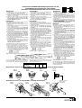
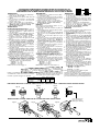
PROCEDURE DE DEMONTAGE-REMONTAGE VERINS PEC-KN
PROCEDURE FOR STRIPPING PEC - KN CYLINDER
WARTUNGS- UND MONTAGEANLEITUNG FÜR PEC-KN ZYLINDER
DEMONTAGE
DEMONTAGE
DISASSEMBLY
1- Démonter les fonds en desserrant les 8
écrous (PEC) ou le circlip avant (KN).
2- Sortir l'ensemble tige/piston du tube de vérin
3- Bloquer l'ensemble tige/piston à l'aide des plats
existant en tête de tige.
4- Retirer les joints à lèvres (2) avec précaution
5- Nettoyer la tige, le piston et l'intérieur du tube
(ne pas utiliser de produits corrosifs ni solvants)
6- Ne pas démonter le piston
REASSEMBLY
Pour obtenir un fonctionnement optimal, il est re-
commandé d'utiliser la graisse fournie.
1- Retirer de la pochette de rechange les joints à
lèvres (2).
2- Enduire légèrement de graisse les joints à lèvres
et les gorges du piston.
3-
Placer le joint à lèvre dans la gorge d'un côté
du piston (fig. A). Respecter le sens de montage
4- Terminer la mise en place du joint dans sa
gorge (fig. B)
5-
Controler le positionnement correct du joint (fig. C)
6-
Retourner l'ensemble tige/piston et monter le
2eme joint en répétant les phases 3,4,5. Respec-
ter les sens de montage des lévres (voir fig. D)
7-
Remonter le segment (5) uniquement sur Ø 100mm
8- Enduire légèrement de graisse l'intérieur et l'en-
trée du tube et les joints à lévres.
9- Placer le piston en biais dans la partie inférieure
du cylindre (fig. E)
10
-Introduire progressivement le joint à lévre, à
l'aide d'un outil plat, sans aspérité et en effec-
tuant un mouvement circulaire de la tige (fig. F).
Ne pas utiliser de tournevis
11
-
Enduire de graisse le pourtour central du piston (❉)
12
-
Pousser le piston dans le cylindre (fig. G)
13
-Aprés avoir remplacé les joints de tige (1) et
joints toriques (3) ou (4), remonter les fonds.
14
-Vérifier que les fonds sont bien mis dans le tube
pour assurer l'alignement et serrer en croix les 8
écrous ou remonter le circlip avant (KN), couple
de serrage recommandé (PEC):
- Ø 32-40 : 7 N.m
- Ø 50-63 : 13,5 N.m
- Ø 80-100 : 27,5 N.m
NOTA: nombre maximum de démontages = 3
Fig. C
Abb. C
Fig. B
Abb. B
Fig. A
Abb. A
1- Entfernen Sie die Endstücke, indem Sie die
8 Muttern (PEC) bzw. den vorderen
Sicherungsring (KN) losen.
2- Nehmen Sie die Einheit bestehend aus Kolben-
stange und Kolben aus dem Zylinderrohr heraus.
3- Blockieren Sie die Einheit aus Kolbenstange und
Kolben an den Schlüsselflächen am Kopf der
Kolbenstange.
4-
Entfernen Sie vorsichtig die Lippendichtungen (2).
5- Reinigen Sie die Kolbenstange, den Kolben und
das Rohr (ätzende Mittel oder Lösemittel sind
nicht zu verwenden).
6- Demontieren Sie nicht den Kolben.
Ein optimales Funktionieren wird durch Verwen-
dung des beigefügten Schmiermittels erreicht.
1- Nehmen Sie die Lippendichtungen (2) aus der
Ersatzteilpackung.
2- Schmieren Sie die Lippendichtungen und die
Kolbenringnuten leicht ein.
3- Legen Sie die Lippendichtung auf einer Seite
des Kolbens (Abb.A) in die Nut ein. Beachten
Sie die Montagerichtung.
4- Schließen Sie die Montage der Dichtung gemäß
(Abb. B) ab.
5-
Überprüfen Sie die richtige Lage der Dichtung (Abb. C)
6- Drehen Sie die Einheit aus Kolbenstange und
Kolben um und legen Sie die 2. Dichtung unter
Wiederholung der Punkte 3,4,5 ein. Beachten
Sie die Montagerichtung der Lippen (Abb.D).
7- Setzen Sie den Führungsring (5) ein nur für
Ø100 mm geeignet
8- Schmieren Sie das Innere und den Eingang des
Rohres sowie die Lippendichtungen leicht ein.
9- Setzen Sie den Kolben schräg in den unteren
Teil des Zylinders (Abb. E) ein.
10
- Schieben Sie die Lippendichtung unter Zuhilfe-
nahme eines glatten Werkzeuges mit einer
drehenden Bewegung in den Zylinder (Abb. F).
Verwenden Sie keinen Schraubendreher.
11-Schmieren Sie den Umfang des Mittelteils des
Kolbens ein (❉).
12-
Schieben Sie den Kolben in den Zylinder (Abb. G)
13-Nachdem Sie die Kolbenstangen- (1) und O-
Ringe (3) oder (4) wieder eingesetzt haben,
schrauben Sie die Endstücke wieder an.
14-Überprüfen Sie die richtige Lage der Endstücke.
Befestigen Sie die 8 Muttern über Kreuz bzw.
denvorderen Sicherungsring (KN). Empfohle-
nen drehmomenten für PEC-Zylinder:
- Ø 32-40 : 7 N.m
- Ø 50-63 : 13,5 N.m
- Ø 80-100 : 27,5 N.m
ANMERKUNG:Max. Anzahl der Demontagen = 3
MONTAGE
REMONTAGE
1- Disassemble the covers by loosening the 8
nuts (PEC) or front circlip (KN).
2-
Remove the rod/piston unit from the cylinder tube.
3- Block the rod/piston unit using the flats on the
rod head.
4- Remove the lip seals (2) carefully.
5- Clean the rod, piston and inside of the tube (do
not use corrosives or solvents).
6- Do not disassemble the piston.
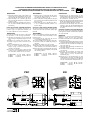
Fig. E
Abb. E
MONTAGE DU PISTON / PISTON ASSEMBLY / MONTAGE DES KOLBENS
Fig. G
Abb. G
MONTAGE DES JOINTS A LEVRES / ASSEMBLY OF THE LIP SEALS / MONTAGE DER LIPPENDICHTUNGEN
❉
Dépôt de graisse
Grease store
Fettkammer
Fig. D
Abb. D
For best results, use grease supplied.
1-
Remove the lip seals from the spare parts bag (3).
2- Coat the lip seals and the piston ring grooves
lightly with grease.
3- Place the lip seal on one side of the piston into
the groove (fig. A). Observe the mounting
direction.
4- Complete fitting of seal into groove (fig. B).
5- Check the correct position of the seal (fig. C).
6- Turn the rod/piston unit around and assemble
the 2nd seal by repeating steps 3,4,5. Observe
the mounting direction of the lips (see fig. D).
7- Install the wear ring (5) only on Ø 100 mm
8- Coat the inside of the tube and its entry as well
as the lip seals lightly with grease.
9- Place the piston diagonally into the bottom part
of the cylinder (fig. E).
10
- Push the lip seal with a circular movement into
the rod using a flat tool (fig. F). Do not use a
screwdriver.
11-Grease the circumference of the middle part of
the piston (❉)
12-Place the piston back into the cylinder (fig. G).
13-After having replaced the rod seals (1) and the
O-rings (3) or (4), reassemble the covers.
14-Check that the ends are properly positioned in
the tube to ensure alignment then tighten the 8
nuts crosswise or assembly the front circlip (KN)
with the following torques (PEC):
- Ø 32-40 : 7 N.m
- Ø 50-63 : 13,5 N.m
- Ø 80-100 : 27,5 N.m
N.B. Max. number of disassemblies = 3
Procédure valable pour version simple tige et tige traversante.
Same procedure for single rod and through rod versions.
Gilt sowohl für die Ausführung mit einfacher als auch mit durchgehender Kolbenstange
.
Lors de l'assemblage des attaches normalisées
sur les vérins PEC, serrer les vis de fixation en
croix suivant couple maxi de serrage ci dessous.
When fixing the standard mountings on the PEC
cylinders tighten the screws crosswise with the
max. torques given below.
Bei der Montage der Standardbefestigungsteile
auf den PEC-Zylindern sind die Schrauben über
Kreuz mit dem nachstehend angegebenen Dreh-
moment anzuziehen.
Ø
Couple maxi
Max. torque
Max. Drehmoment
32-40 50-63 80-100
7 13,5 27,5
(N.m)
Fig. F
Abb. F

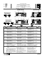
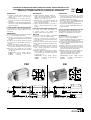
PROCEDURE DE DEMONTAGE-REMONTAGE VERINS PEC-KN ANTIROTATION
PROCEDURE FOR STRIPPING ANTI-ROTATION PEC-KN-CYLINDERS
WARTUNGS- UND MONTAGEANLEITUNG FÜR VERDREHSICHERE PEC-KN-ZYLINDER
DEMONTAGE
1- Démonter la plaque avant en desserrant la vis
centrale (A) tout en immobilisant la tige à l'aide
des deux plats (D) existant en tête de celle-ci.
2- Retirer la plaque + les colonnettes (B) (il n'est
pas nécessaire de démonter les colonnettes de
la plaque avant)
3- Suite du démontage: identique aux phases 1
à 6 des vérins PEC-KN standard (voir page
précédente).
Pièces de rechange / PEC-KN antirotation
Les pochettes de rechange présentées en
première page sont également valables pour
les vérins PEC-KN en version antirotation
REMONTAGE
Procéder au remontage du vérin en commençant
par les phases 1 à 14 (voir page précédente)
15
-
Introduire, avec précaution, les colonnettes (B)
dans les bagues de guidages (C) prévues à cet
effet.
16
- Enduire la vis centrale (A) de Loctite 262
17
- Rentrer la tige du vérin en poussant sur la
plaque.
18
- Visser manuellement la vis centrale (A).
19
- Sortir et rentrer manuellement l'ensemble
plaque et tige (s'assurer de l'absence de
résistance mécanique)
20
- Serrer la vis centrale (A) au couple préconisé
ci-dessous tout en immobilisant la tige à l'aide
des deux plats existant en tête de celle-ci.
Ø 20-25 (KN)= 8 N.m Ø 80 = 67 N.m
Ø 32-40 = 19,5 N.m Ø 100 = 84 N.m
Ø 50-63 = 38,5 N.m
PEC
KN
DISASSEMBLY
1- Block the piston rod using the flats (D) on the
rod head and disassemble the front plate by
loosening the middle screw (A).
2- Draw off the plate and the guide bars (B) (you
do not need to disassemble the guide bars from
the front cover).
3- Disassemble the rest as described in steps 1
to 6 for standard PEC-KN cylinders (see
previous page).
Spar parts / Anti-rotation PEC-KN cylinder
The spare parts kits described on the first page
can also be used for the anti-rotation cylinders type
PEC-KN.
REASSEMBLY
Begin to reassemble the cylinder by following steps
1 to 14 described under "Reassembly" on the
previous page).
15
-
Carefully push the guide bars (B) into the
corresponding guiding rings (C).
16
- Coat the middle screw (A) with Loctite 262.
17
- Insert the rod into the cylinder by pushing on
the plate.
18
- Tighten the middle screw (A) by hand.
19
- Move the plate and rod unit in and out by hand
(make sure there is no mechanical resistance).
20
- Block the piston rod using the flats (D) on the
rod head and tighten the middle screw (A) with
the following torques:
Ø 20-25 (KN)= 8 N.m Ø 80 = 67 N.m
Ø 32-40 = 19,5 N.m Ø 100 = 84 N.m
Ø 50-63 = 38,5 N.m
DEMONTAGE
1- Blockieren Sie die Kolbenstange an den
Schlüsselflächen (D) am Kopf der Kolbenstange
und entfernen sie die vordere Platte, indem Sie
die Schraube in der Mitte (A) lösen.
2- Ziehen Sie die Platte und die Führungsstangen
(B) ab (die Führungsstangen müssen nicht von
der vorderen Platte abmontiert werden).
3- Demontieren Sie die übrigen Teile wie in den
Schritten 1 bis 6 für die Standardzylinder des
Typs PEC-KN beschrieben (siehe vorangehen-
de Seite).
Ersatzteile / Verdrehsichere PEC-KN-Zylinder
Die auf der ersten Seite aufgeführten Ersatzteil-
beutel gelten auch für die verdrehsicheren Zylinder
des Typs PEC-KN.
MONTAGE
Beginnen Sie mit dem Zusammenbau des
Zylinders, indem Sie die unter "Montage"
beschriebenen Schritte 1 bis 14 durchführen (siehe
vorhergehende Seite).
15
-
Führen Sie die Führungsstangen (B) vorsichtig
in die dafür bestimmten Führungsringe (C) ein.
16
- Schmieren Sie die Schraube in der Mitte (A)
mit Loctite 262 ein.
17
- Führen Sie die Kolbenstange ein, indem Sie auf
die Platte drücken.
18
- Schrauben Sie die Schraube in der Mitte (A)
von Hand ein.
19
- Bewegen Sie die Einheit aus Platte und
Kolbenstange hinein und heraus (stellen Sie
sicher, dass es keinen mechanischen
Widerstand gibt).
20
- Blockieren Sie die Kolbenstange an den
Schlüsselflächen am Kopf der Kolbenstange
und ziehen Sie die Schraube in der Mitte (A)
mit den nachstehenden Drehmomenten fest:
Ø 20-25 (KN)= 8 N.m Ø 80 = 67 N.m
Ø 32-40 = 19,5 N.m Ø 100 = 84 N.m
Ø 50-63 = 38,5 N.m
PEC KN
(A)
(B)
(B)
(C)
(D)
(A)
(B)
(B)
(C)
(D)
Seite wird geladen ...
Seite wird geladen ...
Seite wird geladen ...
-
 1
1
-
 2
2
-
 3
3
-
 4
4
-
 5
5
-
 6
6


Asco Series 442 449 Short Stroke Cylinder Type PEC KN Bedienungsanleitung
- Typ
- Bedienungsanleitung
in anderen Sprachen
- English: Asco Series 442 449 Short Stroke Cylinder Type PEC KN Owner's manual
- français: Asco Series 442 449 Short Stroke Cylinder Type PEC KN Le manuel du propriétaire
- español: Asco Series 442 449 Short Stroke Cylinder Type PEC KN El manual del propietario
- italiano: Asco Series 442 449 Short Stroke Cylinder Type PEC KN Manuale del proprietario
- Nederlands: Asco Series 442 449 Short Stroke Cylinder Type PEC KN de handleiding

