Yamaha TG500 Benutzerhandbuch
- Kategorie
- Musikinstrumente
- Typ
- Benutzerhandbuch


FCC INFORMATION (U.S.A.)
1. IMPORTANT NOTICE: DO NOT MODIFY THIS UNIT!
This product, when installed as indicated in the instructions contained in this manual, meets FCC requirements. Modifications not expressly approved
by Yamaha may void your authority, granted by the FCC, to use the product.
2. IMPORTANT: When connecting this product to accessories and/or another product use only high quality shielded cables. Cable/s supplied with this
product MUST be used. Follow all installation instructions. Failure to follow instructions could void your FCC authorization to use this product in the
USA.
3. NOTE: This product has been tested and found to comply with the requirements listed in FCC Regulations, Part 15 for Class ”B” digital devices.
Compliance with these requirements provides a reasonable level of assurance that your use of this product in a residential environment will not
result in harmful interference with other electronic devices. This equipment generates/uses radio frequencies and, if not installed and used according
to the instructions found in the users manual, may cause interference harmful to the operation of other electronic devices. Compliance with FCC
regulations does not guarantee that interference will not occur in all installations. If this product is found to be the source of interference, which can
be determined by turning the unit ”OFF” and ”ON”, please try to eliminate the problem by using one of the following measures:
Relocate either this product or the device that is being affected by the interference.
Utilize power outlets that are on different branch (circuit breaker or fuse) circuits or install AC line filter/s.
In the case of radio or TV interference, relocate/reorient the antenna. If the antenna lead-in is 300 ohm ribbon lead, change the lead-in to co-axial type
cable.
If these corrective measures do not produce satisfactory results, please contact the local retailer authorized to distribute this type of product. If you
can not locate the appropriate retailer, please contact Yamaha Corporation of America, Electronic Service Division, 6600 Orangethorpe Ave, Buena
Park, CA 90620
The above statements apply ONLY to those products distributed by Yamaha Corporation of America or its subsidiaries.
* This applies only to products distributed by YAMAHA CORPORATION OF AMERICA.
Dette apparat overholder det gaeldende EF-direktiv
vedrørende radiostøj.
Cet appareil est conforme aux prescriptions de la
directive communautaire 87/308/CEE.
Diese Geräte entsprechen der EG-Richtlinie 82/
499/EWG und/oder 87/308/EWG.
This product complies with the radio frequency
interference requirements of the Council Direc-
tive 82/499/EEC and/or 87/308/EEC.
Questo apparecchio è conforme al D.M.13 aprile
1989 (Direttiva CEE/87/308) sulla soppressione
dei radiodisturbi.
Este producto está de acuerdo con los requisitos
sobre interferencias de radio frequencia fijados
por el Consejo Directivo 87/308/CEE.
YAMAHA CORPORATION
Connecting the Plug and Cord
IMPORTANT. The wires in this mains lead are coloured in accordance with the following
code:
BLUE : NEUTRAL
BROWN : LIVE
As the colours of the wires in the mains lead of this apparatus may not correspond with the
coloured markings identifying the terminals in your plug proceed as follows:
The wire which is coloured BLUE must be connected to the terminal which is marked with
the letter N or coloured BLACK.
The wire which is coloured BROWN must be connected to the terminal which is marked
with the letter L or coloured RED.
Making sure that neither core is connected to the earth terminal of the three pin plug.
* This applies only to products distributed by YAMAHA - KEMBLE MUSIC (U.K.) LTD.
IMPORTANT NOTICE FOR THE UNITED KINGDOM
Litiumbatteri!
Bör endast bytas av servicepersonal.
Explosionsfara vid felaktig hantering.
VAROITUS!
Lithiumparisto, Räjähdysvaara.
Pariston saa vaihtaa ainoastaan alan
ammattimies.
ADVARSEL!
Lithiumbatteri!
Eksplosionsfare. Udskiftning må kun foretages
af en sagkyndig, – og som beskrevet i
servicemanualen.
CANADA
THIS DIGITAL APPARATUS DOES NOT EXCEED THE “CLASS B” LIMITS FOR RADIO
NOISE EMISSIONS FROM DIGITAL APPARATUS SET OUT IN THE RADIO INTERFER-
ENCE REGULATION OF THE CANADIAN DEPARTMENT OF COMMUNICATIONS.
LE PRESENT APPAREIL NUMERIQUE N’EMET PAS DE BRUITS RADIOELECTRIQUES
DEPASSANT LES LIMITES APPLICABLES AUX APPAREILS NUMERIQUES DE LA “CLASSE
B” PRESCRITES DANS LE REGLEMENT SUR LE BROUILLAGE RADIOELECTRIQUE
EDICTE PAR LE MINISTERE DES COMMUNICATIONS DU CANADA.
* This applies only to products distributed by YAMAHA CANADA MUSIC LTD.

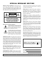
SPECIAL MESSAGE SECTION
PRODUCT SAFETY MARKINGS: Yamaha electronic prod-
ucts may have either labels similar to the graphics shown
below or molded/stamped facsimiles of these graphics on the
enclosure. The explanation of these graphics appears on this
page. Please observe all cautions indicated on this page and
those indicated in the safety instruction section.
methods used to produce them, meet these goals. In keeping
with both the letter and the spirit of the law, we want you
to be aware of the following:
Battery Notice: This product MAY contain a small non-
rechargcable battery which (if applicable) is soldered in
place. The average life span of this type of battery is
approximately five years. When replacement becomes
neccessary, contact a qualified service representative to
perform the replacement.
Warning: Do not attempt to recharge, disassemble, or
incinerate this type of battery. Keep all batteries away from
children. Dispose of used batteries promptly and as regulated
by applicable laws. Note: In some areas, the servicer is
required by law to return the defective parts. However, you
do have the option of having the servicer dispose of these
parts for you.
Disposal Notice: Should this product become damaged
beyond repair, or for some reason its useful life is considered
to be at an end, please observe all local, state, and federal
regulations that relate to the disposal of products that contain
lead, batteries, plastics, etc.
NOTICE: Service charges incurred due to lack of knowl-
edge relating to how a function or effect works (when the
unit is operating as designed) are not covered by the manu-
facturer’s warranty, and are therefore the owners responsi-
bility. Please study this manual carefully and consult your
dealer before requesting service.
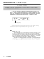
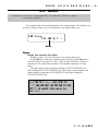
NAME PLATE LOCATION: The graphic below indicates
the location of the name plate. The model number, serial
number, power requirements, etc., are located on this plate.
You should record the model number, serial nunber, and the
date of purchase in the spaces provided below and retain this
manual as a permanent record of your purchase.
CAUTION: TO REDUCE THE RISK OF
ELECTRIC SHOCK, DO NOT REMOVE
COVER (OR BACK). NO USER-SERVICEABLE
PARTS INSIDE. REFER SERVICING TO
QUALIFIED SERVICE PERSONNEL
RISK OF ELECTRIC SHOCK
DO NOT OPEN
CAUTION
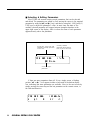
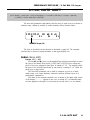
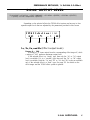
The exclamation point within the equilateral
triangle is intended to alert the user to the
presence of important operating and mainte-
nance (servicing) instructions in the litera-
ture accompanying the product.
The lightning flash with arrowhead symbol
within the equilateral triangle is intended to
alert the user to the presence of uninsulated
“dangerous voltage” within the product’s
enclosure that may be of sufficient magni-
tude to constitute a risk of electrical shock.
IMPORTANT NOTICE: All Yamaha electronic products are
tested and approvend by an independent safety testing labo-
ratory in order that you may be sure that when it is properly
installed and used in its normal and customary manner, all
foreseeable risks have been eliminated. DO NOT modify this
unit or commission others to do so unless specifically author-
ized by Yamaha. Product performance and/or safety standards
may be diminished. Claims filed under the expressed warranty
may be denied if the unit is/has been modified. Implied
warranties may also be affected.
SPECFICATIONS SUBJECT TO CHANGE: The informa-
tion contained in this manual is believed to be correct at the
time of printing. However, Yamaha reserves the right to
change or modify any of the specifications without notice or
obligation to update existing units.
ENVIRONMENTAL ISSUES: Yamaha strives to produce
products that are both user safe and environmentally friendly.
We sincerely believe that our products and the production
Model
Serial No.
Purchase Date
● Explanation of Graphical Symbols
This information on safety is provided to comply with U.S.A. laws, but should be observed by users in all countires.
92-4691

IMPORTANT SAFETY INSTRUCTIONS
INFORMATION RELATING TO PERSONAL INJURY, ELECTRICAL SHOCK,
AND FIER HAZARD POSSIBILITIES HAS BEEN INCLUDED IN THIS LIST.
PLEASE KEEP THIS MANUAL
8. This product was NOT designed for use in wet/damp
locations and should not be used near water or exposed to
rain. Examples of wet/damp locations are; near a swim-
ming pool, spa, tub, sink, or wet basement.
9. This product should be used only with the components
supplied or; a cart, rack, or stand that is recommended by
the manufacturer. If a cart, rack, or stand is used, please
observe all safety markings and instructions that accom-
pany the accessory product.
10.The power supply cord (plug) should be disconnected
from the outlet when electronic products are to be left
unused for extended periods of time. Cords should also be
disconnected when there is a high probability of lightening
and/or electrical storm activity.
11.Care should be taken that objects do not fall and liquids
are not spilled into the enclosure through any openings
that may exist.
12.Electrical/electronic products should be serviced by a
qualified service person when:
a. The power supply cord has been damaged; or
b. Objects have fallen, been inserted, or liquids have been
spilled into the enclosure through openings; or
c. The product has been exposed to rain; or
d. The product does not operate, exhibits a marked change
in performance; or
e. The product has been dropped, or the enclosure of the
product has been damaged.
13.Do not attempt to service this product beyond that de-
scribed in the user-maintenance instructions. All other
servicing should be referred to qualified service personnel.
14.This product, either alone or in combination with an
amplifier and headphones or speaker/s, may be capable of
producing sound levels that could cause permanent hear-
ing loss. DO NOT operate for a long period of time at a
high volume level or at a level that is uncomfortable. If
you experience any hearing loss or ringing in the cars, you
should cousult an audiologist. IMPORTANT: The louder
the sound, the shorter the time period before damage
occurs.
15.Some Yamaha products may have benches and/or acces-
sory mounting fixtures that are either supplied as a part of
the product or as optional accessories. Some of these items
are designed to be dealer assembled or installed. Please
make sure that benches are stable and any optional fixtures
(where applicable) are well secured BEFORE using. Benches
supplied by Yamaha are designed for seating only. No
other uses are recommended.
WARNING — When using any electrical or electronic prod-
uct, basic precautions should always be followed. These
precautions include, but are not limited to, the following:
1. Read all Safety Instructions, Installation Instructions, Spe-
cial Message Section items, and any Assembly Instruc-
tions found in this manual BEFORE making any connections,
including connection to the main supply.
2. Main Power Suplly Verifications: Yamaha products are
manufactured specifically for the supply voltage in the
area where they are to be sold. If you should move, or if
any doubt exists about the supply voltage in your area,
please contact your dealer for supply voltage verification
and (if applicable) instructions. The required supply volt-
age is printed on the name plate. For name plate location,
please refer to the graphic found in the Special Message
Section of this manual.
3. This product may be equipped with a polarized plug (one
blade wider than the other). If you are unable to insert the
plug into the outlet, turn the plug over and try again. If the
problem persists, contact electrician to have the obsolete
outlet replaced. Do NOT defeat the safety purpose of the
plug.
4. Some electronic products utilize external power supplies
or adapters. DO NOT connect this type of product to any
power supply or adapter other than one described in the
owners manual, on the name plate, or specifically recom-
mended by Yamaha.
5. WARNING: Do not place this product or any other objects
on the power cord or place it in a position where anyone
could walk on, trip over, or roll anything over power or
connecting cords of any kind. The use of an extension cord
is not recommended! If you must use an extension cord,
the minimume wire size for a 25' cord (or less) is 18 AWG.
NOTE: The smaller the AWG number, the larger the
current handling capacity. For longer extension cords,
consult a local electrician.
6. Ventilation: Electronic products, unless specifically de-
signed for enclosed installations, should be placed in
locations that do not interfere with proper ventilation. If
instructions for enclosed installations are not provided, it
must be assumed that unobstructed ventilation is required.
7. Temperature considerations: Electronic products should be
installed in locations that do not significantly contribute to
their operating temperature. Placement of this product
close to heat sources such as; radiators, heat registers and
other devices that produce heat should be avoided.
This information on safety is provided to comply with U.S.A. laws, but should be observed by users in all countires.
92-4692

i
The TG500 Tone Generator delivers the incredible Yamaha AWM2 sound
with improved quality and versatility. In addition to superior sound, the TG500
features “Quick Edit” modes that provide fast, easy access to the most impor-
tant voice and performance editing jobs so you can customize the sound with-
out having to deal with the details. Of course, you still have full programming
power when you want to do some serious voicing. In terms of sound and
programming power, the TG500 offers unprecedented levels of quality and
performance.
We urge you to read the owner’s manuals thoroughly in order to realize the
full potential of the TG500 (see “About the Manual” on page 5), and keep the
manuals in a safe place for future reference.
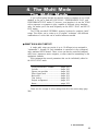
MAIN FEATURES
● AWM2 Sound, 64-note Polyphony
2nd-generation Advanced Wave Memory (AWM2) technology delivers
dazzling, true-to-life sound with 64-note polyphony.
● Large-capacity Waveform ROM
A huge 8-megabyte waveform ROM provides the kind of capacity required
for stunning, true-to-life sound.
● Expandable Waveform RAM
Up to 1-megabyte of waveform RAM can be installed to allow loading of
external samples via waveform cards or the MIDI Sample Dump protocol.
● 4-layer Performance Combinations
Voices can be played individually, or up to four voices can be combined
and “layered” to form performance combinations.
● 384 Presets and 192 User RAM Locations
The TG500 has 384 presets including 252 voices, 4 multi-instrument drum
voices, and 128 performance combinations. 192 internal RAM locations addi-
tionally store 126 voices, 2 drum voices, and 64 performance combinations.
The TG500 also provides RAM memory for 16 multi-play setups.
● Advanced Digital Filters
Programmable digital filters allow the TG500 sound to be tailored as re-
quired. The filters also feature a resonance parameter equivalent to that found
on the SY77 and SY99 Music Synthesizers.

ii
● Top-quality Effects
The basic quality of the TG500 voices is further enhanced by a range of
programmable effects offering quality rivalling some of the finest separate
signal processing systems.
● Other Features
• Slots for dual external memory card sets (VOICE and WAVE).
• Easy-to-read 24-character × 2-line backlit LCD display.
• Recognizes individual key aftertouch.
• Stereo L/R and 4 individual audio outputs.

iii
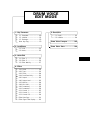
APPENDIX
UTILITY MODE / WAVE EDIT MODE
MULTI EDIT MODE
DRUM VOICE EDIT MODE
VOICE EDIT MODE
PERFORMANCE EDIT MODE
GETTING STARTED
FEATURE REFERENCE

iv
4. The Multi Mode ...................... 35
•WHAT’S IN A MULTI SETUP? .........35
•MULTI PLAY POLYPHONY &
DYNAMIC VOICE ALLOCATION ......36
•SELECTING A MULTI SETUP..........36
■ Editing a Multi Setup ...........................36
•THE MULTI PARAMETER EDIT
SCREENS ............................................37
•SELECTING DIFFERENT
INSTRUMENTS FOR EDITING.........38
•NO STORE OPERATION
REQUIRED ..........................................38
■ Further Possibilities… ..........................38
5. Voice Editing & Effects ............. 39
■ Bypassing the Effects While
Editing ....................................................41
■ Further Possibilities… ..........................41
Precautions .................................. 3
About the Manual .......................... 5
■ The Getting Started Section .................5
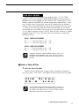
■ Icons.........................................................6
■ The Feature Reference Section ...........7
The Controls & Connectors.............. 8
■ Front Panel..............................................8
■ Rear Panel.............................................11
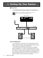
1. Setting Up Your System ............ 12
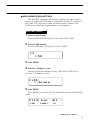
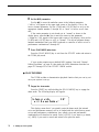
■ Connections...........................................12
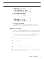
■ Power-on Procedure.............................15
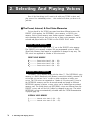
2. Selecting And Playing Voices..... 16
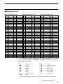
■ The Preset, Internal, & Card Voice
Memories ...............................................16
■ Select a Voice & Play..........................17
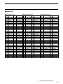
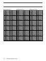
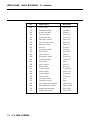
■ Internal Voice List.................................19
3. The Performance Mode............. 22
■ The Preset, Internal, & Card
Performance Memories ........................22
■ Play the Performance
Combinations.........................................24
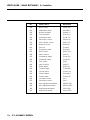
■ Internal Performance List ....................25
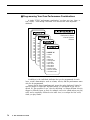
■ Programming Your Own Performance
Combinations.........................................26
■ Further Possibilities… ..........................34
CONTENTS
Getting Started

v
General Editing Procedure
■ Edit Mode Access.................................45
■ Selecting Specific Edit Functions .......46
■ Selecting & Editing Parameters..........48
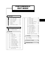
Performance Edit Mode
Layer Selection & Muting
•Layer Selection ..............................................50
•Layer Muting ..................................................50
1: Quick Edit
1-1: Voice Amplitude EG Offset .............52
1-2: Voice Filter Offset.............................54
1-3: Voice LFO Offset ..............................55
1-4: Voice Controller ................................56
1-5: Voice Setting .....................................57
1-6: Effect 1...............................................58
1-7: Effect 2...............................................58
1-8: Effect Wet:Dry Balance....................59
2: Level/Name
2-1: Performance Total Level..................60
2-2: Performance Name...........................61
3: Full Edit
3-1: Layer
3-1-01: Voice.........................................62
3-1-02: Volume......................................63
3-1-03: Pan............................................64
3-1-04: Note Shift .................................65
3-1-05: Tune..........................................66
3-1-06: Note Limit-L .............................67
3-1-07: Note Limit-H.............................67
3-1-08: Velocity Limit-L........................69
3-1-09: Velocity Limit-H .......................69
3-1-10: MC3 Enable .............................71
3-1-11: MC4 Enable .............................71
3-1-12: Layer Initialize .........................73
3-1-13: Layer Exchange ......................74
Layer Data Copy...................................75
Feature Reference
3-2: Effect
3-2-01: Mode.........................................76
3-2-02: Type..........................................77
3-2-03: Send..........................................78
3-2-04: Send Sensitivity.......................79
3-2-05: Output.......................................80
3-2-06: Output Level ............................81
3-2-07: Wet:Dry.....................................82
3-2-08: Mix Level..................................83
3-2-09: Parameter 1 .............................84
3-2-10: Parameter 2 .............................84
3-2-11: Control 1 ..................................85
3-2-12: Control 2 ..................................85
3-2-13: Control LFO .............................88
Effect Data Copy ..................................89
Effect Signal Flow Display ..................90
4: Recall/Init.
4-1: Recall..................................................91
4-2: Initialize ..............................................92
Performance
Performance Compare..............................93
Performance Store....................................94
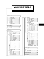
Voice Edit Mode
1: Quick Edit
1-1: Wave Select ......................................96
1-2: Amplitude EG ....................................98
1-3: Filter................................................. 100
1-4: LFO.................................................. 102
1-5: Effect 1............................................ 103
1-6: Effect 2............................................ 103
1-7: Effect Wet:Dry ................................ 104
2: Level/Name
2-1: Level ................................................ 105
2-2: Name ............................................... 106

vi
3: Full Edit
3-1: Oscillator
3-1-01: Wave Select.......................... 107
3-1-02: Parameter.............................. 109
3-2: AEG
3-2-01: Level ...................................... 111
3-2-02: Rate ....................................... 111
3-2-03: Scale Point............................ 115
3-2-04: Scale Offset .......................... 116
3-2-05: Sensitivity .............................. 117
AEG Data Copy ................................. 118
3-3: Filter
3-3-01: Parameter.............................. 119
3-3-02: Level ...................................... 124
3-3-03: Rate ....................................... 124
3-3-04: Scale Point............................ 127
3-3-05: Scale Offset .......................... 128
3-3-06: Sensitivity .............................. 129
Filter Data Copy ................................ 130
3-4: PEG
3-4-01: Level ...................................... 131
3-4-02: Rate ....................................... 131
3-4-03: Sensitivity .............................. 134
Pitch EG Data Copy.......................... 135
3-5: LFO
3-5-01: Parameter.............................. 136
3-5-02: Depth ..................................... 138
3-5-03: Sensitivity .............................. 139
LFO Data Copy.................................. 140
3-6: Controller
3-6-01: Pitch Bend, After Touch...... 141
3-6-02: After Touch Depth ............... 142
3-6-03: MIDI Controller 1 ................. 145
3-6-04: MIDI Controller 2 ................. 145
3-6-05: MIDI Controller 3 ................. 147
3-6-06: MIDI Controller 4 ................. 147
Controller Data Copy ........................ 149
3-7: Effect
3-7-01: Mode...................................... 150
3-7-02: Type....................................... 151
3-7-03: Send....................................... 152
3-7-04: Output Level ......................... 153
3-7-05: Wet:Dry.................................. 154
3-7-06: Mix Level............................... 155
3-7-07: Parameter 1 .......................... 156
3-7-08: Parameter 2 .......................... 156
3-7-09: Control 1 ............................... 157
3-7-10: Control 2 ............................... 157
3-7-11: Control LFO .......................... 160
Effect Data Copy ............................... 161
Effect Signal Flow Display ............... 162
4: Recall/Init.
4-1: Recall............................................... 163
4-2: Initialize ........................................... 164
Voice
Voice Compare....................................... 165
Voice Store ............................................. 166
Drum Voice Edit Mode
1: Key Parameter
1-1: Parameter ....................................... 168
1-2: Initialize ........................................... 171
1-3: Exchange ........................................ 172
Drum Key Copy...................................... 173
2: Level/Name
2-1: Level ................................................ 174
2-2: Name ............................................... 175
3: Quick Edit
3-1: Effect 1............................................ 176
3-2: Effect 2............................................ 176
3-3: Effect Wet:Dry ................................ 177
4: Effect
4-01: Mode.............................................. 178
4-02: Type............................................... 179
4-03: Send .............................................. 180
4-04: Send Sensitivity ........................... 181
4-05: Output............................................ 182

vii
4-06: Output Level............................. 183
4-07: Wet:Dry..................................... 184
4-08: Mix Level .................................. 185
4-09: Parameter 1 ............................. 186
4-10: Parameter 2 ............................. 186
4-11: Control 1................................... 187
4-12: Control 2................................... 187
4-13: Control LFO.............................. 190
Effect Data Copy ............................... 191
Effect Signal Flow Display ............... 192
5: Recall/Init.
5-1: Recall............................................... 193
5-2: Initialize ........................................... 194
Drum Voice Compare ............................ 195
Drum Voice Store .................................. 196
Multi Edit Mode
Multi Instrument Selection .......................... 198
1: Parameter................................................ 199
2: Name ........................................................ 202
3: Initialize ................................................... 203
4: Effect
4-01: Mode ......................................... 204
4-02: Type .......................................... 205
4-03: Send.......................................... 206
4-04: Output ....................................... 208
4-05: Output Level............................. 209
4-06: Wet:Dry..................................... 210
4-07: Mix Level .................................. 211
4-08: Parameter 1 ............................. 212
4-09: Parameter 2 ............................. 212
4-10: Control 1................................... 213
4-11: Control 2................................... 213
4-12: Control LFO.............................. 216
Effect Data Copy ............................... 217
Effect Signal Flow Display ............... 218
Utility Mode
1: System
1-1: Setup ............................................... 220
1-2: Effect Bypass ................................. 221
1-3: Output.............................................. 222
2: Controller
2-1: MIDI Control ................................... 223
2-2: Volume Control .............................. 225
3: MIDI
3-1: Parameter ....................................... 227
3-2: Filter................................................. 230
3-3: Bulk Dump ...................................... 231
3-4: Program Change Table................. 232
4: Card
4-1: Bank................................................. 233
4-2: Load................................................. 234
4-3: Save................................................. 235
4-4: Format ............................................. 236
5: Wave ........................................................ 237
The Wave Edit Mode .................................. 238
1: Waveform
1-1: Assign.............................................. 239
1-2: Enable ............................................. 240
1-3: Name ............................................... 241
2: Sample..................................................... 242
3: Initialize ................................................... 245
4: Sample Dump
4-1: Sample Receive ............................. 246
4-2: Sample Transmit ............................ 247
5: Card Load ............................................... 248

viii
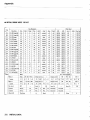
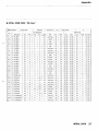
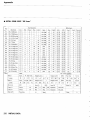
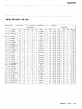
Appendix
INITIAL PERFORMANCE LIST
(Preset 1) ................................................ 300
INITIAL PERFORMANCE LIST
(Preset 2) ................................................ 301
INITIAL PERFORMANCE LIST
(Internal).................................................. 302
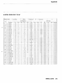
INITIAL VOICE LIST (Preset 1)........... 303
INITIAL VOICE LIST (Preset 2)........... 304
INITIAL VOICE LIST (Preset 3)........... 305
INITIAL VOICE LIST (Preset 4)........... 306
INITIAL VOICE LIST (Internal 1)......... 307
INITIAL VOICE LIST (Internal 2)......... 308
WAVE LIST (Preset 1).......................... 309
WAVE LIST (Preset 2).......................... 310
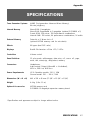
SPECIFICATIONS........................................ 311
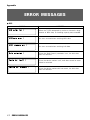
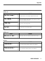
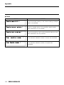
ERROR MESSAGES ................................... 312
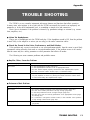
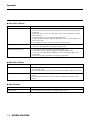
TROUBLE SHOOTING................................ 315
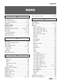
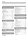
INDEX ........................................................... 317
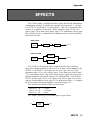
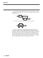
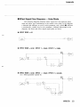
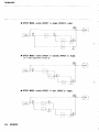
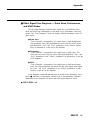
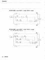
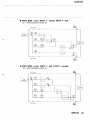
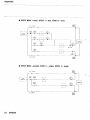
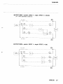
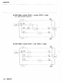
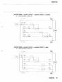
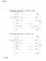
EFFECTS ...................................................... 251
Effect Signal Flow Diagrams —
Voice Mode............................................. 253
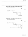
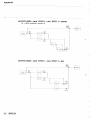
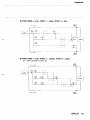
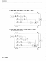
Effect Signal Flow Diagrams —
Drum Voice, Performance, and
Multi Modes ............................................ 261
The Effects & Their Parameters.......... 271
INSTALLATION OF THE SYEMB06
EXPANSION MEMORY BOARD .......... 282
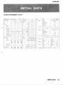
INITIAL DATA
INITIAL PERFORMANCE “InitPerf.” .... 283
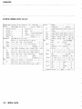
INITIAL NORMAL VOICE “Init Vce” .... 284
INITIAL DRUM VOICE “DR Kit”........... 285
INITIAL DRUM VOICE “DR Zones”..... 287
INITIAL DRUM VOICE “DR GMIDI” .... 289
INITIAL DRUM VOICE “DR Efect” ...... 291
INITIAL MULTI “Init Mlt” ....................... 293
SYSTEM SETUP.................................... 294
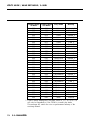
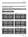
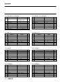
PERFORMANCE BLANK CHART........ 295
NORMAL VOICE BLANK CHART........ 296
DRUM VOICE BLANK CHART ............ 297
MULTI BLANK CHART.......................... 298
SYSTEM SETUP BLANK CHART ....... 299

Getting Started

2

3
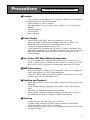
Precautions
■ Location
Do not expose the instrument to the following conditions to avoid deforma-
tion, discoloration, or more serious damage.
• Direct sunlight (e.g. near a window).
• High temperatures (e.g. near a heat source, outside, or in a car during the
daytime).
• Excessive humidity.
• Excessive dust.
• Strong vibration.
■ Power Supply
• Turn the power switch OFF when the instrument is not in use.
• The power supply cord should be unplugged from the AC outlet if the
instrument is not to be used for an extended period of time.
• Unplug the instrument during electric storms.
• Avoid plugging the instrument into the same AC outlet as appliances with
high power consumption, such as electric heaters or ovens. Also avoid using
multi-plug adapters since these can result in reduced sound quality and
possibly damage.
■ Turn Power OFF When Making Connections
• To avoid damage to the instrument and other devices to which it is con-
nected (a sound system, for example), turn the power switches of all related
devices OFF prior to connecting or disconnecting audio and MIDI cables.
■ MIDI Connections
• When connecting the TG500 to MIDI equipment, be sure to use high-quality
cables made especially for MIDI data transmission.
• Avoid MIDI cables longer than about 15 meters. Longer cables can pick up
electrical noise that can causes data errors.
■ Handling and Transport
• Never apply excessive force to the controls, connectors or other parts of the
instrument.
• Always unplug cables by gripping the plug firmly, not by pulling on the
cable.
• Disconnect all cables before moving the instrument.
• Physcal shocks caused by dropping, bumping, or placing heavy objects on
the instrument can result in scratches and more seious damage.
■ Cleaning
• Clean the cabinet and panel with a dry soft cloth.
• A slightly damp cloth may be used to remove stubborn grime and dirt.
• Never use cleaners such as alcohol or thinner.
• Avoid placing vinyl objects on top of the instrument (vinyl can stick to and
discolor the surface).
!! PLEASE READ THIS BEFORE PROCEEDING !!

4
■ Electrical Interference
• This instrument contains digital circuitry and may cause interference if
placed too close to radio or television receivers. If this occurs, move the
instrument further away from the affected equipment.
■ Data Backup
• The TG500 contains a special long-life battery that retains the contents of
its internal voice, performance, multi, and wave memory (when installed)
even when the power is turned OFF. The backup battery should last for
several years. When the backup battery needs to be replaced “Change bat-
tery!” will appear on the display when the power is turned on. When this
happens, have the backup battery replaced by qualified Yamaha service
personnel. DO NOT ATTEMPT TO REPLACE THE BACKUP BATTERY
YOURSELF!
• Internal memory data can be corrupted due to incorrect operation. Be sure to
“save” important data to memory card frequently so you have a backup to
revert to if something happens to damage the data in memory.
■ Service and Modification
• The TG500 contains no user serviceable parts. Opening it or tampering with
it in anyway can lead to irreparable damage and possibly electric shock.
Refer all servicing to qualified YAMAHA personnel.
■ Third-party Software
• Yamaha can not take any responsibility for software produced for this prod-
uct by third-party manufacturers. Please direct any questions or comments
about such software to the manufacturer or their agents.
YAMAHA is not responsible for damage caused by improper handling
or operation.

5
About the Manual
The TG500 manual has two sections —
Getting Started
and
Feature
Reference
.
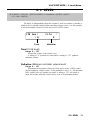
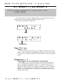
■ The Getting Started Section
In addition to an overview of the TG500 controls and connectors (page 8),
the Getting Started section contains five chapters that take you through the
main procedures you will need to know to become familiar with your TG500:
1. Setting Up Your System [Page 12]
Basic system connections, MIDI settings, and powering up your system.
2. Selecting And Playing Voices [Page 16]
Selecting and playing voices from the INTERNAL, PRESET and CARD
memories.
3. The Performance Mode [Page 22]
Selecting and playing performance combinations from the INTERNAL,
PRESET and CARD memories, and programming original performance
combinations.
4. The Multi Mode [Page 35]
Creating and using multi setups that allow up to 16 separate “instru-
ments” to be independenty controlled from an external sequencer, com-
puter, or similar device.
5. Voice Editing & Effects [Page 39]
Some ideas to help you program original voices in a smooth and effi-
cient manner.
We recommend that you go through the chapters in sequence while actually
carrying out the procedures on your TG500. Once you’ve gone through the
entire Getting Started section in this way, you should be familiar enough with
the TG500 to need only the Feature Reference section in future.

6
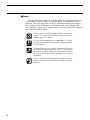
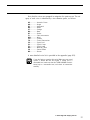
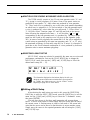
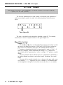
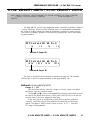
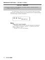
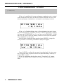
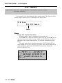
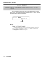
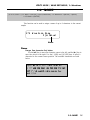
■ Icons
The following simple icons are used throughout the Getting Started section
of the manual to draw attention to important points and information where
necessary. The icons also make it easier to differentiate between information
that you should read immediately and information that can be skipped until
later, hopefully helping you to become familiar with the TG500 in the quickest,
most efficient manner possible.
This icon warns of possible hardware damage, software mal-
function, or any other serious problem that may occur due to
improper operation or set up.
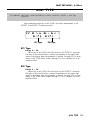
This icon marks information that you must read — i.e. impor-
tant steps or procedures that are essential for proper, efficient,
or easy operation.
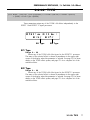
The magnifying-glass icon indicates information that may not
be essential for general operation, but is a more detailed
explanation of a feature, a description of the principle involved,
etc. You can skip this information if full details are not required
immediately.
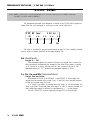
Hints or ideas that are not specifically musical but may make
operation easier or more interesting are marked by the light-
bulb icon.
IMPORTANT
CAUTION
DETAIL
HINT

7
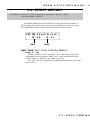
■ The Feature Reference Section
The Feature Reference section is the “nuts and bolts” reference for the
TG500, individually describing its many functions in detail. The Feature Refer-
ence section is divided into 5 main chapters, each describing the various func-
tions within a particular TG500 edit or utility mode.
1. Performance Edit Mode ................... [Page 49]
2. Voice Edit Mode ................... .............[Page 95]
3. Drum Voice Edit Mode........ .............[Page 167]
4. Multi Edit Mode..................... .............[Page 197]
5. Utility Mode/Wave Edit Mode........... [Page 219]
Once you have become familiar with the way the TG500 works by going
through the Getting Started section, you should only need to refer to the Fea-
ture Reference section from time to time to get details on functions you’ve
never used before, or refresh your memory about functions that you don’t use
very often.
Each chapter of the Feature Reference section has its own table of contents,
so you should be able to locate any particular function quickly and easily.
Functions and references can also be located by referring to the index at the
back of the manual.

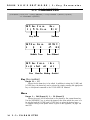
8
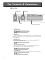
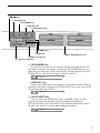
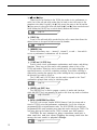
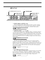
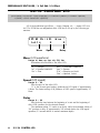
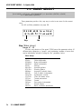
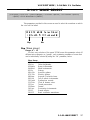
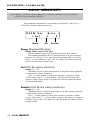
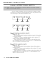
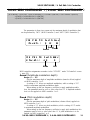
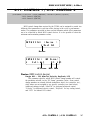
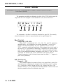
The Controls & Connectors
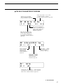
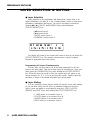
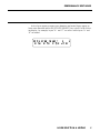
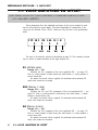
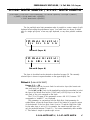
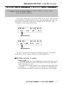
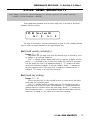
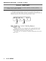
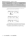
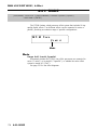
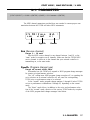
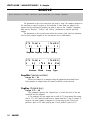
■ Front Panel
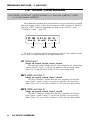
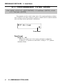
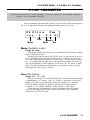
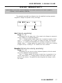
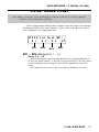
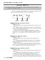
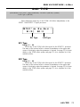
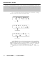
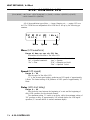
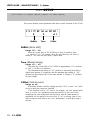
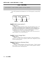
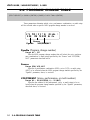
1 [POWER] Switch
Press to turn the TG500 power on or off.
page 15.
2 PHONES Jack
Accepts a standard pair of stereo headphones (1/4" stereo phone plug) for
headphone monitoring of the TG500 sound without the need for external ampli-
fication equipment.
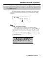
3 VOLUME Control
Adjusts the volume of the sound delivered via the rear-panel OUTPUT
jacks as well as the PHONES jack.
page 12.
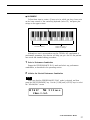
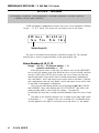
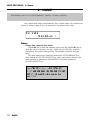
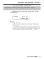
4 Liquid Crystal Display Panel
This 24-character × 2-line backlit liquid crystal display panel shows all
essential information for easy operation and programming.
page 17.
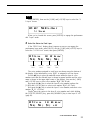
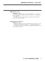
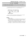
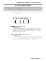
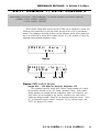
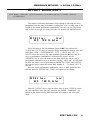
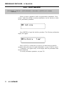
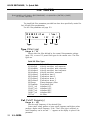
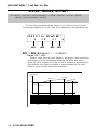
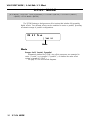
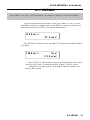
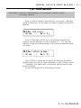
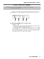
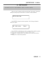
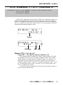
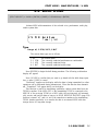
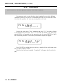
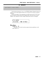
5 [PLAY MODE] Key
Alternately selects the TG500’s voice, performance, and multi play modes.
page 14.
1[POWER] Switch
2PHONES
3VOLUME Control
4Liquid Crystal Display Panel
Seite wird geladen ...
Seite wird geladen ...
Seite wird geladen ...
Seite wird geladen ...
Seite wird geladen ...
Seite wird geladen ...
Seite wird geladen ...
Seite wird geladen ...
Seite wird geladen ...
Seite wird geladen ...
Seite wird geladen ...
Seite wird geladen ...
Seite wird geladen ...
Seite wird geladen ...
Seite wird geladen ...
Seite wird geladen ...
Seite wird geladen ...
Seite wird geladen ...
Seite wird geladen ...
Seite wird geladen ...
Seite wird geladen ...
Seite wird geladen ...
Seite wird geladen ...
Seite wird geladen ...
Seite wird geladen ...
Seite wird geladen ...
Seite wird geladen ...
Seite wird geladen ...
Seite wird geladen ...
Seite wird geladen ...
Seite wird geladen ...
Seite wird geladen ...
Seite wird geladen ...
Seite wird geladen ...
Seite wird geladen ...
Seite wird geladen ...
Seite wird geladen ...
Seite wird geladen ...
Seite wird geladen ...
Seite wird geladen ...
Seite wird geladen ...
Seite wird geladen ...
Seite wird geladen ...
Seite wird geladen ...
Seite wird geladen ...
Seite wird geladen ...
Seite wird geladen ...
Seite wird geladen ...
Seite wird geladen ...
Seite wird geladen ...
Seite wird geladen ...
Seite wird geladen ...
Seite wird geladen ...
Seite wird geladen ...
Seite wird geladen ...
Seite wird geladen ...
Seite wird geladen ...
Seite wird geladen ...
Seite wird geladen ...
Seite wird geladen ...
Seite wird geladen ...
Seite wird geladen ...
Seite wird geladen ...
Seite wird geladen ...
Seite wird geladen ...
Seite wird geladen ...
Seite wird geladen ...
Seite wird geladen ...
Seite wird geladen ...
Seite wird geladen ...
Seite wird geladen ...
Seite wird geladen ...
Seite wird geladen ...
Seite wird geladen ...
Seite wird geladen ...
Seite wird geladen ...
Seite wird geladen ...
Seite wird geladen ...
Seite wird geladen ...
Seite wird geladen ...
Seite wird geladen ...
Seite wird geladen ...
Seite wird geladen ...
Seite wird geladen ...
Seite wird geladen ...
Seite wird geladen ...
Seite wird geladen ...
Seite wird geladen ...
Seite wird geladen ...
Seite wird geladen ...
Seite wird geladen ...
Seite wird geladen ...
Seite wird geladen ...
Seite wird geladen ...
Seite wird geladen ...
Seite wird geladen ...
Seite wird geladen ...
Seite wird geladen ...
Seite wird geladen ...
Seite wird geladen ...
Seite wird geladen ...
Seite wird geladen ...
Seite wird geladen ...
Seite wird geladen ...
Seite wird geladen ...
Seite wird geladen ...
Seite wird geladen ...
Seite wird geladen ...
Seite wird geladen ...
Seite wird geladen ...
Seite wird geladen ...
Seite wird geladen ...
Seite wird geladen ...
Seite wird geladen ...
Seite wird geladen ...
Seite wird geladen ...
Seite wird geladen ...
Seite wird geladen ...
Seite wird geladen ...
Seite wird geladen ...
Seite wird geladen ...
Seite wird geladen ...
Seite wird geladen ...
Seite wird geladen ...
Seite wird geladen ...
Seite wird geladen ...
Seite wird geladen ...
Seite wird geladen ...
Seite wird geladen ...
Seite wird geladen ...
Seite wird geladen ...
Seite wird geladen ...
Seite wird geladen ...
Seite wird geladen ...
Seite wird geladen ...
Seite wird geladen ...
Seite wird geladen ...
Seite wird geladen ...
Seite wird geladen ...
Seite wird geladen ...
Seite wird geladen ...
Seite wird geladen ...
Seite wird geladen ...
Seite wird geladen ...
Seite wird geladen ...
Seite wird geladen ...
Seite wird geladen ...
Seite wird geladen ...
Seite wird geladen ...
Seite wird geladen ...
Seite wird geladen ...
Seite wird geladen ...
Seite wird geladen ...
Seite wird geladen ...
Seite wird geladen ...
Seite wird geladen ...
Seite wird geladen ...
Seite wird geladen ...
Seite wird geladen ...
Seite wird geladen ...
Seite wird geladen ...
Seite wird geladen ...
Seite wird geladen ...
Seite wird geladen ...
Seite wird geladen ...
Seite wird geladen ...
Seite wird geladen ...
Seite wird geladen ...
Seite wird geladen ...
Seite wird geladen ...
Seite wird geladen ...
Seite wird geladen ...
Seite wird geladen ...
Seite wird geladen ...
Seite wird geladen ...
Seite wird geladen ...
Seite wird geladen ...
Seite wird geladen ...
Seite wird geladen ...
Seite wird geladen ...
Seite wird geladen ...
Seite wird geladen ...
Seite wird geladen ...
Seite wird geladen ...
Seite wird geladen ...
Seite wird geladen ...
Seite wird geladen ...
Seite wird geladen ...
Seite wird geladen ...
Seite wird geladen ...
Seite wird geladen ...
Seite wird geladen ...
Seite wird geladen ...
Seite wird geladen ...
Seite wird geladen ...
Seite wird geladen ...
Seite wird geladen ...
Seite wird geladen ...
Seite wird geladen ...
Seite wird geladen ...
Seite wird geladen ...
Seite wird geladen ...
Seite wird geladen ...
Seite wird geladen ...
Seite wird geladen ...
Seite wird geladen ...
Seite wird geladen ...
Seite wird geladen ...
Seite wird geladen ...
Seite wird geladen ...
Seite wird geladen ...
Seite wird geladen ...
Seite wird geladen ...
Seite wird geladen ...
Seite wird geladen ...
Seite wird geladen ...
Seite wird geladen ...
Seite wird geladen ...
Seite wird geladen ...
Seite wird geladen ...
Seite wird geladen ...
Seite wird geladen ...
Seite wird geladen ...
Seite wird geladen ...
Seite wird geladen ...
Seite wird geladen ...
Seite wird geladen ...
Seite wird geladen ...
Seite wird geladen ...
Seite wird geladen ...
Seite wird geladen ...
Seite wird geladen ...
Seite wird geladen ...
Seite wird geladen ...
Seite wird geladen ...
Seite wird geladen ...
Seite wird geladen ...
Seite wird geladen ...
Seite wird geladen ...
Seite wird geladen ...
Seite wird geladen ...
Seite wird geladen ...
Seite wird geladen ...
Seite wird geladen ...
Seite wird geladen ...
Seite wird geladen ...
Seite wird geladen ...
Seite wird geladen ...
Seite wird geladen ...
Seite wird geladen ...
Seite wird geladen ...
Seite wird geladen ...
Seite wird geladen ...
Seite wird geladen ...
Seite wird geladen ...
Seite wird geladen ...
Seite wird geladen ...
Seite wird geladen ...
Seite wird geladen ...
Seite wird geladen ...
Seite wird geladen ...
Seite wird geladen ...
Seite wird geladen ...
Seite wird geladen ...
Seite wird geladen ...
Seite wird geladen ...
Seite wird geladen ...
Seite wird geladen ...
Seite wird geladen ...
Seite wird geladen ...
Seite wird geladen ...
Seite wird geladen ...
Seite wird geladen ...
Seite wird geladen ...
Seite wird geladen ...
Seite wird geladen ...
Seite wird geladen ...
Seite wird geladen ...
Seite wird geladen ...
Seite wird geladen ...
Seite wird geladen ...
Seite wird geladen ...
Seite wird geladen ...
Seite wird geladen ...
Seite wird geladen ...
Seite wird geladen ...
Seite wird geladen ...
Seite wird geladen ...
Seite wird geladen ...
Seite wird geladen ...
Seite wird geladen ...
Seite wird geladen ...
Seite wird geladen ...
Seite wird geladen ...
Seite wird geladen ...
Seite wird geladen ...
Seite wird geladen ...
Seite wird geladen ...
Seite wird geladen ...
Seite wird geladen ...
Seite wird geladen ...
Seite wird geladen ...
Seite wird geladen ...
Seite wird geladen ...
Seite wird geladen ...
Seite wird geladen ...
Seite wird geladen ...
Seite wird geladen ...
Seite wird geladen ...
Seite wird geladen ...
Seite wird geladen ...
Seite wird geladen ...
Seite wird geladen ...
Seite wird geladen ...
-
 1
1
-
 2
2
-
 3
3
-
 4
4
-
 5
5
-
 6
6
-
 7
7
-
 8
8
-
 9
9
-
 10
10
-
 11
11
-
 12
12
-
 13
13
-
 14
14
-
 15
15
-
 16
16
-
 17
17
-
 18
18
-
 19
19
-
 20
20
-
 21
21
-
 22
22
-
 23
23
-
 24
24
-
 25
25
-
 26
26
-
 27
27
-
 28
28
-
 29
29
-
 30
30
-
 31
31
-
 32
32
-
 33
33
-
 34
34
-
 35
35
-
 36
36
-
 37
37
-
 38
38
-
 39
39
-
 40
40
-
 41
41
-
 42
42
-
 43
43
-
 44
44
-
 45
45
-
 46
46
-
 47
47
-
 48
48
-
 49
49
-
 50
50
-
 51
51
-
 52
52
-
 53
53
-
 54
54
-
 55
55
-
 56
56
-
 57
57
-
 58
58
-
 59
59
-
 60
60
-
 61
61
-
 62
62
-
 63
63
-
 64
64
-
 65
65
-
 66
66
-
 67
67
-
 68
68
-
 69
69
-
 70
70
-
 71
71
-
 72
72
-
 73
73
-
 74
74
-
 75
75
-
 76
76
-
 77
77
-
 78
78
-
 79
79
-
 80
80
-
 81
81
-
 82
82
-
 83
83
-
 84
84
-
 85
85
-
 86
86
-
 87
87
-
 88
88
-
 89
89
-
 90
90
-
 91
91
-
 92
92
-
 93
93
-
 94
94
-
 95
95
-
 96
96
-
 97
97
-
 98
98
-
 99
99
-
 100
100
-
 101
101
-
 102
102
-
 103
103
-
 104
104
-
 105
105
-
 106
106
-
 107
107
-
 108
108
-
 109
109
-
 110
110
-
 111
111
-
 112
112
-
 113
113
-
 114
114
-
 115
115
-
 116
116
-
 117
117
-
 118
118
-
 119
119
-
 120
120
-
 121
121
-
 122
122
-
 123
123
-
 124
124
-
 125
125
-
 126
126
-
 127
127
-
 128
128
-
 129
129
-
 130
130
-
 131
131
-
 132
132
-
 133
133
-
 134
134
-
 135
135
-
 136
136
-
 137
137
-
 138
138
-
 139
139
-
 140
140
-
 141
141
-
 142
142
-
 143
143
-
 144
144
-
 145
145
-
 146
146
-
 147
147
-
 148
148
-
 149
149
-
 150
150
-
 151
151
-
 152
152
-
 153
153
-
 154
154
-
 155
155
-
 156
156
-
 157
157
-
 158
158
-
 159
159
-
 160
160
-
 161
161
-
 162
162
-
 163
163
-
 164
164
-
 165
165
-
 166
166
-
 167
167
-
 168
168
-
 169
169
-
 170
170
-
 171
171
-
 172
172
-
 173
173
-
 174
174
-
 175
175
-
 176
176
-
 177
177
-
 178
178
-
 179
179
-
 180
180
-
 181
181
-
 182
182
-
 183
183
-
 184
184
-
 185
185
-
 186
186
-
 187
187
-
 188
188
-
 189
189
-
 190
190
-
 191
191
-
 192
192
-
 193
193
-
 194
194
-
 195
195
-
 196
196
-
 197
197
-
 198
198
-
 199
199
-
 200
200
-
 201
201
-
 202
202
-
 203
203
-
 204
204
-
 205
205
-
 206
206
-
 207
207
-
 208
208
-
 209
209
-
 210
210
-
 211
211
-
 212
212
-
 213
213
-
 214
214
-
 215
215
-
 216
216
-
 217
217
-
 218
218
-
 219
219
-
 220
220
-
 221
221
-
 222
222
-
 223
223
-
 224
224
-
 225
225
-
 226
226
-
 227
227
-
 228
228
-
 229
229
-
 230
230
-
 231
231
-
 232
232
-
 233
233
-
 234
234
-
 235
235
-
 236
236
-
 237
237
-
 238
238
-
 239
239
-
 240
240
-
 241
241
-
 242
242
-
 243
243
-
 244
244
-
 245
245
-
 246
246
-
 247
247
-
 248
248
-
 249
249
-
 250
250
-
 251
251
-
 252
252
-
 253
253
-
 254
254
-
 255
255
-
 256
256
-
 257
257
-
 258
258
-
 259
259
-
 260
260
-
 261
261
-
 262
262
-
 263
263
-
 264
264
-
 265
265
-
 266
266
-
 267
267
-
 268
268
-
 269
269
-
 270
270
-
 271
271
-
 272
272
-
 273
273
-
 274
274
-
 275
275
-
 276
276
-
 277
277
-
 278
278
-
 279
279
-
 280
280
-
 281
281
-
 282
282
-
 283
283
-
 284
284
-
 285
285
-
 286
286
-
 287
287
-
 288
288
-
 289
289
-
 290
290
-
 291
291
-
 292
292
-
 293
293
-
 294
294
-
 295
295
-
 296
296
-
 297
297
-
 298
298
-
 299
299
-
 300
300
-
 301
301
-
 302
302
-
 303
303
-
 304
304
-
 305
305
-
 306
306
-
 307
307
-
 308
308
-
 309
309
-
 310
310
-
 311
311
-
 312
312
-
 313
313
-
 314
314
-
 315
315
-
 316
316
-
 317
317
-
 318
318
-
 319
319
-
 320
320
-
 321
321
-
 322
322
-
 323
323
-
 324
324
-
 325
325
-
 326
326
-
 327
327
-
 328
328
-
 329
329
-
 330
330
-
 331
331
-
 332
332
-
 333
333
-
 334
334


Yamaha TG500 Benutzerhandbuch
- Kategorie
- Musikinstrumente
- Typ
- Benutzerhandbuch
in anderen Sprachen
- English: Yamaha TG500 User manual
- français: Yamaha TG500 Manuel utilisateur
- español: Yamaha TG500 Manual de usuario
- italiano: Yamaha TG500 Manuale utente
- русский: Yamaha TG500 Руководство пользователя
- Nederlands: Yamaha TG500 Handleiding
- português: Yamaha TG500 Manual do usuário
- dansk: Yamaha TG500 Brugermanual
- polski: Yamaha TG500 Instrukcja obsługi
- čeština: Yamaha TG500 Uživatelský manuál
- svenska: Yamaha TG500 Användarmanual
- Türkçe: Yamaha TG500 Kullanım kılavuzu
- suomi: Yamaha TG500 Ohjekirja
- română: Yamaha TG500 Manual de utilizare
Verwandte Artikel
-
Yamaha SY85 Benutzerhandbuch
-
Yamaha CS6X Bedienungsanleitung
-
Yamaha S80 Benutzerhandbuch
-
Yamaha MOTIF ES7 Benutzerhandbuch
-
-
-
-
-
-