Pride 101 Bedienungsanleitung
- Kategorie
- Massagegeräte
- Typ
- Bedienungsanleitung

Including Models: C1, C5, C6, C11, C15, D30,
310, 560, 570, 660, 670, and 101
LIFT CHAIR
Pride Mobility Products Italia S.r.l.
Via del Progresso - ang. Via del Lavoro
Loc. Prato della Corte
00065 - Fiano Romano (RM)
Pride Mobility Products Europe B.V.
Castricummer Werf 26
1901 RW Castricum
The Netherlands
www.pridemobility.com
*INFMANU3686*
SERIES

SAFETY GUIDELINES
LIFT CHAIR SERIES
NOTE: This owner’s manual is compiled from the latest specifications and product information avail-
able at the time of publication. We reserve the right to make changes as they become necessary. Any
changes to our products may cause slight variations between the illustrations and explanations in
this manual and the product you have purchased. The latest/current version of this manual is avail-
able on our website.
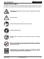
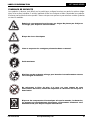
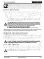
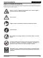
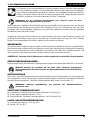
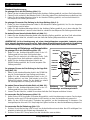
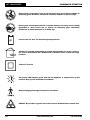
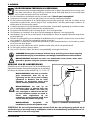
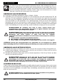
The symbols below are used throughout this owner's manual and on the product to identify warnings and
important information. It is very important for you to read them and understand them completely.
WARNING! Indicates a potentially hazardous condition/situation. Failure to follow
designated procedures can cause either personal injury, component damage, or
malfunction. On the product, this icon is represented as a black symbol on a yellow
triangle with a black border.
MANDATORY! These actions should be performed as specified. Failure to perform
mandatory actions can cause personal injury and/or equipment damage. On the
product, this icon is represented as a white symbol on a blue dot with a white
border.
PROHIBITED! These actions are prohibited. These actions should not be performed
at any time or in any circumstances. Performing a prohibited action can cause
personal injury and/or equipment damage. On the product, this icon is represented
as a black symbol with a red circle and red slash.
Copyright © 2009
Pride Mobility Products Corporation
INFMANU3686/Rev C/August 2009
Please fill out the following information for quick reference:
Pride Provider:_____________________________________________________________________
Address:__________________________________________________________________________
Phone Number:__________________________
Purchase Date:__________________________ Serial Number:_____________________________
088 609 661

Lift Chair Series www.pridemobility.com 3
LIFT CHAIR SERIES
LABEL INFORMATION
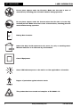
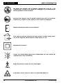
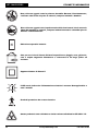
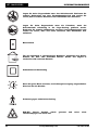
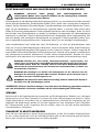
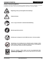
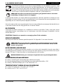
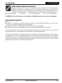
PRODUCT SAFETY SYMBOLS
The symbols below represent labels used on the product to identify warnings, mandatory actions, and pro-
hibited actions. It is very important for you to read and understand these symbols completely. Do not remove
these labels from your product. Please note that not all of the symbols may be used on your lift chair model.
Pinch/Crush Points Hazard! Do not place objects or appendages in the path
of moving parts.
Read and follow the information in the owner’s manual.
Maximum weight capacity
Do not connect an extension lead to the AC/DC converter or the battery
charger.
Electrical Hazard
Removal of grounding prong can create electrical hazard. If necessary,
properly install an approved 3-pronged adapter to an electrical outlet having
2-pronged plug access.
Properly dispose of all electronic components, including the external
transformer, hand control, batteries, actuator motors, and wiring. Contact
your authorized Pride Provider for more information.

4 www.pridemobility.com Lift Chair Series
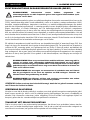
LIFT CHAIR SERIES
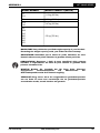
LABEL INFORMATION
Battery Door Location
Green LED indicates power to the unit is on. Not applicable to all models.
Indoor Use Only. Avoid exposure to rain, snow, ice, salt, or standing water.
Maintain and store in a clean and dry environment.
Class II Equipment
Do not place objects under the lift chair. Make sure the area is clear of
obstructions, including pets and small children during operation.
Degree of protection against electric shock.
This product has been tested and complies to IEC 60601-1-2.
Do not place objects under the footrest when the lift chair is in the fully
reclined position. Make sure area is clear of obstructions, including pets and
small children during operation.

Lift Chair Series www.pridemobility.com 5
LIFT CHAIR SERIES
TABLE OF CONTENTS
SAFETY GUIDELINES .......................................................................................... 2
LABEL INFORMATION ......................................................................................... 3
I. INTRODUCTION................................................................................................ 6
SAFETY ....................................................................................................................................................................... 6
PURCHASER’S AGREEMENT.................................................................................................................................... 6
INFORMATION EXCHANGE....................................................................................................................................... 6
II. GENERAL GUIDELINES ................................................................................... 7
MODIFICATIONS......................................................................................................................................................... 7
WEIGHT LIMITATIONS ............................................................................................................................................... 7
PINCH/CRUSH HAZARDS .......................................................................................................................................... 7
DEGREE OF PROTECTION/MODE OF OPERATION ............................................................................................... 7
STORAGE AND OPERATION TEMPERATURES ...................................................................................................... 7
EMI/RFI ........................................................................................................................................................................ 8
SHIPPING AND DELIVERY......................................................................................................................................... 8
MOTOR VEHICLE TRANSPORT ................................................................................................................................ 8
III. YOUR LIFT CHAIR .......................................................................................... 9
BODY COMPONENTS ................................................................................................................................................ 9
ELECTRICAL COMPONENTS .................................................................................................................................. 10
IV. ASSEMBLY/DISASSEMBLY .......................................................................... 12
LIFT CHAIR SET UP.................................................................................................................................................. 12
LIFT CHAIR PLACEMENT......................................................................................................................................... 14
BATTERY INSTALLATION ........................................................................................................................................ 14
LIFT CHAIR DISASSEMBLY ..................................................................................................................................... 15
FABRIC REMOVAL/INSTALLATION......................................................................................................................... 16
V. OPERATION ................................................................................................... 19
OPERATION PRECAUTIONS ................................................................................................................................... 19
HAND CONTROL OPERATION ................................................................................................................................ 19
VI. TROUBLESHOOTING.................................................................................... 22
FREQUENTLY ASKED QUESTIONS........................................................................................................................ 22
VII. CARE AND MAINTENANCE ......................................................................... 24
FABRIC CARE ........................................................................................................................................................... 24
ELECTRONICS CARE............................................................................................................................................... 24
DISPOSAL AND RECYCLING................................................................................................................................... 24
VIII. WARRANTY ................................................................................................ 25
APPENDIX ........................................................................................................ 127

6 www.pridemobility.com Lift Chair Series
LIFT CHAIR SERIES
SAFETY
WELCOME to Pride Mobility Products Europe B.V. (Pride). The product you have purchased com-
bines state-of-the-art components with safety, comfort, and styling in mind. We are confident the
design features will provide you with the conveniences you expect during your daily activities.
Understanding how to safely operate and care for this product should bring you years of trouble-
free operation and service.
Read and follow all instructions, warnings, and notes in this manual and all other accompanying literature
before attempting to operate this product for the first time. In addition, your safety depends upon you, as well
as your provider, caregiver, or healthcare professional in using good judgement.
If there is any information in this manual which you do not understand, or if you require additional assistance
for setup or operation, please contact your authorized Pride Provider. Failure to follow the instructions,
warnings, and notes in this manual and those located on your Pride product can result in personal
injury or product damage and will void Pride’s product warranty.
PURCHASER’S AGREEMENT
By accepting delivery of this product, you promise that you will not change, alter, or modify this product or
remove or render inoperable or unsafe any guards, shields, or other safety features of this product; fail, refuse
or neglect to install any retrofit kits from time to time provided by Pride to enhance or preserve the safe use
of this product.
INFORMATION EXCHANGE
We want to hear your questions, comments, and suggestions about this manual. We would also like to hear
about the safety and reliability of your new lift chair and about the service you received from your authorized
Pride Provider. Please notify us of any change of address, so we can keep you apprised of important infor-
mation about safety, new products, and new options that can increase your ability to use and enjoy your lift
chair. Please feel free to contact us at the address below:
Pride Mobility Products Europe B.V.
Castricummer Werf 26
1901 RW Castricum
The Netherlands
NOTE: If you ever lose or misplace your product registration card or your copy of this manual, contact
us and we will be glad to send you a new one immediately.
I. INTRODUCTION

Lift Chair Series www.pridemobility.com 7
LIFT CHAIR SERIES
Your lift chair is a state-of-the-art life-enhancement device designed to increase mobility. Pride
provides an extensive variety of products to best fit your individual needs. Please be aware that
the final selection and purchasing decision regarding the type of lift chair to be used is the
responsibility of you, the lift chair user, if capable of making such a decision, and/or your health-
care professional (i.e., medical doctor, physical therapist, etc.).
MANDATORY! Read and follow the information provided in this owner’s manual
before attempting to operate your lift chair for the first time.
There are certain situations, including some medical conditions, where you will need to practice operating the
lift chair in the presence of a trained attendant. A trained attendant can be defined as a family member or
healthcare professional specially trained in assisting you with performing various daily living activities while
safely operating a lift chair.
Below are some precautions, tips, and other safety considerations that will help you become accustomed to
operating the lift chair in a safe manner.
MODIFICATIONS
Pride has designed and engineered your lift chair to provide maximum comfort and utility. However, to pre-
vent personal injury and/or damage to your lift chair, you should not modify, add, remove, or disable any
feature, part, or function of your lift chair. Unauthorized modifications may also void your product’s warranty.
NOTE: Use Pride parts only for all repairs and replacements.
WEIGHT LIMITATIONS
Your lift chair is rated for a maximum weight capacity. Refer to “Appendix A” for more information.
MANDATORY! Stay within the specified weight capacity of your lift chair. Pride will
not be held responsible for injuries and/or product damage resulting from failure to
observe weight limitations.
PINCH/CRUSH HAZARDS
The scissor and lift mechanisms are labeled as pinch/crush point hazards on your lift chair. Keep clear of
these areas and make sure the path of motion is unobstructed. See figure 3.1 for pinch/crush point locations.
WARNING! Do not place objects or appendages in the path of moving parts.
DEGREE OF PROTECTION/MODE OF OPERATION
Class II equipment/Type B protection against electric shock
Degree of protection against the ingress of solid/liquids—IPX1
Mode of operation—Maximum Duty Cycle: 2min ON/18min OFF
STORAGE AND OPERATION TEMPERATURES
Transportation or storage: -75°C/-104°F to 70°C/158°F
Operation: 10°C/50°F to 40°C/104°F
II. GENERAL GUIDELINES

8 www.pridemobility.com Lift Chair Series
LIFT CHAIR SERIES
II. GENERAL GUIDELINES
ELECTROMAGNETIC AND RADIO FREQUENCY INTERFERENCE (EMI/RFI)
WARNING! Laboratory tests have shown that electromagnetic and radio frequency
waves can have an adverse affect on the performance of electrically-powered
devices, such as lift chairs.
Electromagnetic and Radio Frequency Interference can come from sources such as cellular phones, mobile
two-way radios (such as walkie-talkies), radio stations, TV stations, amateur radio (HAM) transmitters, wire-
less computer links, microwave signals, paging transmitters, and medium-range mobile transceivers used by
emergency vehicles. In some cases, these waves can cause unintended movement or damage to the control
system of electrically-powered devices. The lift chair user can help prevent electromagnetic interference by
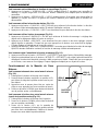
maintaining a minimum distance between portable and mobile RF communications equipment. It is recom-
mended that at least 3 meters (9 feet) of distance be maintained between the lift chair and any handheld
equipment emitting 10 W or more of output power. Refer to the manufacturer’s literature for the handheld
device to determine the maximum output power of that device.
Every electrically-powered device has an immunity (or resistance) to EMI. The higher the immunity level, the
greater the protection against EMI. Per EMC standards, this product has passed immunity testing and is rated
as a Group 1, Class B product, meaning the lift chair uses RF energy only for its internal function. Therefore,
its RF emissions are very low and are not likely to cause any interference in nearby electronic equipment
making the lift chair suitable for use in all establishments, including domestic establishments and hospitals.
WARNING! Be aware that cell phones, two-way radios, laptops, and other types of
radio transmitters may cause unintended movement of your electrically-powered
device due to EMI. Exercise caution when using any of these items while operating
your lift chair.
WARNING! The addition of accessories or components to the lift chair can increase
the susceptibility of the chair to EMI. Do not modify your lift chair in any way not
authorized by Pride.
WARNING! Your lift chair itself can disturb the performance of other electrical
devices located nearby, such as alarm systems.
NOTE: If unintended motion occurs, discontinue use of the lift chair. Contact Pride to report the incident.
SHIPPING AND DELIVERY
Before using your lift chair, make sure your delivery is complete as some components may be packaged
individually. If you do not receive a complete delivery, please contact your authorized Pride Provider imme-
diately. Where damage has occurred during transport, either to the packaging or content, please contact the
delivery company responsible.
MOTOR VEHICLE TRANSPORT
If you will be transporting your lift chair in a motor vehicle, individual components (external transformer, etc.)
should be secured against slipping. The lift chair itself must also be secured against slipping (a possible
hazard during vehicle braking).

Lift Chair Series www.pridemobility.com 9
LIFT CHAIR SERIES
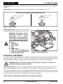
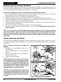
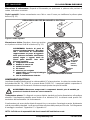
BODY COMPONENTS
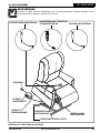
This section describes the features of your lift chair. Carefully review the function and location
of each item described, and note that the illustrations and option locations shown in this manual
may not reflect the type of lift chair that you own.
III. YOUR LIFT CHAIR
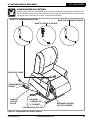
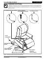
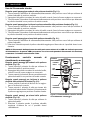
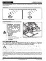
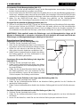
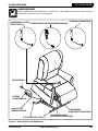
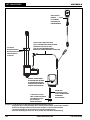
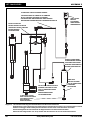
Figure 3.1 Pride Lift Chair Main Components
DUAL MOTOR HAND CONTROL
EXTERNAL
TRANSFORMER
LIFT MECHANISM
(PINCH POINT)
LEG LEVELERS (FOUR TOTAL)
SCISSOR
MECHANISMS
(PINCH POINT)
POWER LEAD
LOW VOLTAGE
CONNECTION CABLE
STANDARD HAND CONTROL
HEAT AND MASSAGE HAND CONTROL

10 www.pridemobility.com Lift Chair Series
LIFT CHAIR SERIES
III. YOUR LIFT CHAIR
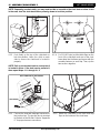
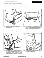
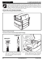
Lift Mechanism: Responds to the hand control commands to position the chair in the sit, recline, and stand
positions.
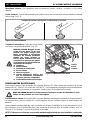
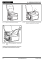
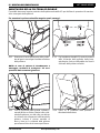
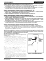
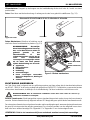
Leg Levelers: Manually rotate up or down in order to stabilize the chair before use (Fig. 3.2).
Figure 3.2 Leg Levelers
Scissor Mechanisms: Extend or retract to take the
chair through the various stages of recline (Fig. 3.3).
WARNING! Pinch/Crush Points
Hazard! Be aware that the lift
mechanism and scissor
mechanisms are a pinch point on
the lift chair. Keep the following
items and similar objects clear of
these points when operating the
lift chair:
appendages
small children
pets
wires
oxygen tubes
loose items, including but not
limited to clothing and blankets
electrical power leads
Figure 3.3 Scissor Mechanism
ROTATE THE LEG LEVELERS TO RAISE OR LOWER THE CHAIR.
SCISSOR
MECHANISM
(PINCH POINT)
ELECTRICAL COMPONENTS
Your Pride Lift Chair is equipped with a low voltage DC electrical system that reduces the standard household
alternating current of 90V AC - 264V AC to direct current (24/39V DC). The electrical components include the
external transformer, batteries, and hand control. Keep these areas free from moisture at all times.
WARNING! Keep all electrical components free from moisture at all times to
prevent shock and/or electrical hazard.
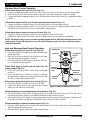
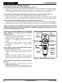
External Transformer: Connects to a standard electrical outlet to provide power to the lift chair. The trans-
former may be equipped with an LED indicator, which shows green when power to the transformer is on.
The external transformer may also come equipped with mounting brackets that allow the transformer to be
mounted to the wall directly under the standard electrical outlet. The screws must be mounted to the wall stud
for security. Refer to “Appendix G” or “Appendix H” for a mounting diagram.
NOTE: Pride is not responsible for damage due to improper installation.

Lift Chair Series www.pridemobility.com 11
LIFT CHAIR SERIES
III. YOUR LIFT CHAIR
Batteries: Provide the power needed to return the lift chair from the recline position to the sit and/or lift
position in the event of a power failure. For those models equipped with a battery backup system, the batteries
are located inside the external transformer.
Hand Control: Contains the controls needed to operate the various functions of the lift chair. Refer to V.
“Operation” for more information. The hand control may be equipped with a quick-release connector, which
enables the user to detach the hand control from the chair, disabling all functions of the hand control.

12 www.pridemobility.com Lift Chair Series
LIFT CHAIR SERIES
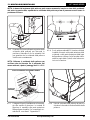
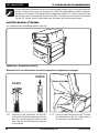
KD
SLEEVE
KD CONNECTION
IV. ASSEMBLY/DISASSEMBLY
Your lift chair may require some assembly before initial use. It may also require disassembly to
make servicing the chair more convenient. If your lift chair is a Knock-Down (KD) model, follow
the instructions in “Lift Chair Set Up.” If your lift chair is not a KD model, proceed to “Lift Chair
Placement.”
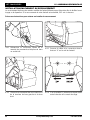
LIFT CHAIR SET UP
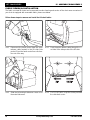
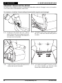
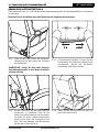
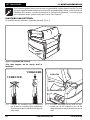
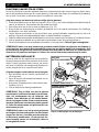
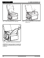
KD models will arrive in the knock-down position (Fig. 4.1).
Figure 4.1 Knock-down (KD) Position
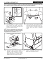
Follow these steps to assemble the lift chair:
4.1.1 Remove the packaging from the back portion
of the chair and check that the locking clip is in
the vertical position. Reposition if necessary.
4.1.2 Slide the left and right KD sleeves of the
chair-back onto the KD connections on the
arms and seat of the chair.
LOCKING CLIP

Lift Chair Series www.pridemobility.com 13
LIFT CHAIR SERIES
IV. ASSEMBLY/DISASSEMBLY
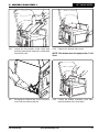
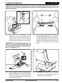
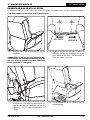
NOTE: Depending on chair width, you may need to slide on one side of the chair-back at a time. If this
is the case, level the chair-back before pressing down to lock into position.
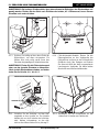
4.1.3 Push firmly on the top of the chair-back to
lock into position. Listen for a click on each
side to ensure the chair-back is locked in
properly.
NOTE: Pull up on the chair-back to ensure that it
is locked in place. If the back can be pulled off,
then repeat steps 4.1.1 through 4.1.3.
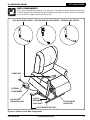
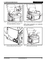
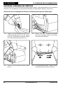
4.1.4 For C6 Lift Chairs, tuck the fabric flaps on the
front of the chair-back and rear of the chair
base down into the frame and secure with the
reusable fastener on each flap. Then, zip the
two sections together.
“CLICK”
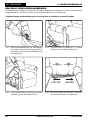
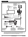
4.1.5
Connect the heat and massage harnesses to
the junction box. The junction box is mounted
to the back of the lift chair. Refer to “Appendix
D” for proper harness connections.
4.1.6 Attach the chair-back to the hook and loop
flaps on the bottom of the chair base.
HEAT CONNECTION TO JUNCTION BOX
JUNCTION BOX
MASSAGE UNIT

14 www.pridemobility.com Lift Chair Series
LIFT CHAIR SERIES
IV. ASSEMBLY/DISASSEMBLY
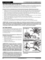
LIFT CHAIR PLACEMENT
Your lift chair should be placed near a standard electrical outlet on dry, level ground where there is ample
room to allow for proper operation. Pride recommends that you have the assistance of an attendant when
positioning the lift chair to avoid the possibility of injury when lifting.
Follow these steps to position the lift chair in a safe manner:
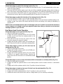
1. Place the back of the lift chair 76 cm (30 in.) from the nearest obstruction while the chair is in the seated
position. This measurement may vary depending on model.
2. Adjust the leg levelers to stabilize the lift chair (Fig. 3.2).
3. Install the batteries into the external transformer if applicable. Refer to “Battery Installation” for more
information.
4. Position the external transformer on the floor in an open, well-ventilated area where it will not be an
obstruction, or if equipped, utilize the optional wall mount.
5. Position the low voltage connection cable where it will not be pinched between the frame and the lift
mechanism.
6. Connect the low voltage connection cable to the external transformer if it is not already connected.
7. Plug the power lead directly into the electrical outlet. Do not use an extension lead!
NOTE: If you discover a problem at any point during the set up and positioning of your lift chair, stop
and contact your authorized Pride Provider immediately. To avoid personal injury and/or product
damage, do not plug the unit into the electrical outlet until the problem is corrected and do not
attempt to fix electrical problems by yourself.
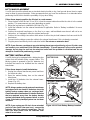
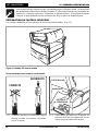
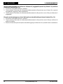
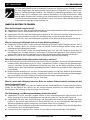
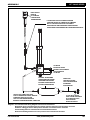
EXTERNAL TRANSFORMER
BATTERY DOOR
POWER LEAD
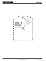
Figure 4.2 Lift Chair Battery Backup Location
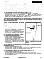
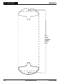
BATTERY INSTALLATION
Your lift chair may be equipped with a battery backup
system that will activate during a power failure. The
backup system is powered by two 9V batteries (not
included) that need to be installed into the external
transformer.
Follow these steps to install the batteries:
1. Unplug the external transformer power lead from
the electrical outlet.
2. Open the marked battery door on the external
transformer.
3. Install two 9V batteries into the external trans-
former (Fig. 4.2).
4. Replace the battery door.
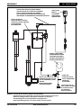
NOTE: Always make sure the external transformer
is equipped with two fresh 9V batteries, since the
battery backup system does not recharge itself.
Fresh batteries are defined as 9V alkaline batteries
that are replaced every time the battery backup
system is activated during a power failure, or once
a year if the battery backup system has not been
activated.
NOTE: If you unplug your lift chair for an extended
period of time (more than one hour), remove the
batteries from the external transformer. The lift
chair will draw power from the batteries even
when it is not in use.
EXTERNAL TRANSFORMER
(BOTTOM VIEW)
POWER LEAD

Lift Chair Series www.pridemobility.com 15
LIFT CHAIR SERIES
LIFT CHAIR DISASSEMBLY
The back portion of KD Lift Chairs can be removed to make service and transport of the chair more convenient.
Follow these steps to disassemble the lift chair:
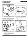
IV. ASSEMBLY/DISASSEMBLY
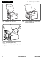
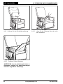
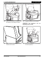
4.3.1 Remove the bottom of the back fabric from
the hook and loop flaps on the chair base.
NOTE: If equipped with a heat and massage
option, be sure to disconnect the heat and/or
massage harnesses from the junction box.
4.3.2 For C6 Lift Chairs, unzip the chair-back from
the chair base, then disengage the reusable
fastener securing the chair-back fabric to the
frame.
4.3.3 Using a large flathead screwdriver, lift the left
and right locking clips on the chair-back one
side at a time to raise the back from the con-
nections on the chair base. As you lift each
locking clip, pull up on the chair-back to lift
that side over the lock.
4.3.4 Lift the chair-back up and away from the
chair base.

16 www.pridemobility.com Lift Chair Series
LIFT CHAIR SERIES
IV. ASSEMBLY/DISASSEMBLY
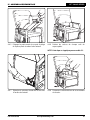
FABRIC REMOVAL/INSTALLATION
The fabric on some lift chairs can be removed to make cleaning and service of the chair more convenient. If
your chair is equipped with removable fabric, please see below.
Follow these steps to remove and install the lift chair fabric:
4.4.1 Disconnect the hand control from the quick
release cable located in the lift chair side
pocket. Place the hand control in a safe loca-
tion out of the way.
4.4.2 Push the quick release cable through the “V”
cut hole in the side pocket of the lift chair.
4.4.3 Slide the left and right side arm covers off of
the metal side arms.
4.4.4 For C6 Lift Chairs, unzip the chaise pad from
the chair-back cover.

Lift Chair Series www.pridemobility.com 17
LIFT CHAIR SERIES
IV. ASSEMBLY/DISASSEMBLY
4.4.5 Loosen the front portion of the chaise pad
from the footrest and remove the chaise pad
from the lift chair.
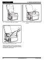
4.4.6 Remove the footrest side covers.
NOTE: This feature does not apply to the C1 Lift
Chair.
4.4.7 Disengage the bottom flap of the chair-back
cover from the bottom seat rail.
4.4.8 Loosen the bottom chair-back cover flaps
from the bottom of the chair-back.

18 www.pridemobility.com Lift Chair Series
LIFT CHAIR SERIES
IV. ASSEMBLY/DISASSEMBLY
4.4.9 Remove the chair-back cover.
4.4.10 Loosen the seat box cover from the left and
right side of the seat box.
4.4.11 Remove the seat box cover.
NOTE: Follow the fabric removal steps in the
reverse order to install the fabric components to
the lift chair.

Lift Chair Series www.pridemobility.com 19
LIFT CHAIR SERIES
OPERATION PRECAUTIONS
There are certain precautions that should be taken during the operation of your lift chair. Read and
follow these precautions carefully in order to ensure safe lift chair operation and to prevent injury
and/or product damage.
Plug the power lead directly into the electrical outlet. Do not use an extension lead!
Do not place anything (for example, a drinking glass) on top of or near the external transformer.
If the external transformer box or hand control requires cleaning, unplug the power lead from the electrical
outlet and use a clean, dry cloth or lightly dampened cloth. Allow ample drying time before plugging the
power lead back into the electrical outlet.
Periodically check the hand control and all power leads for visible damage.
Keep the hand control away from all heated surfaces.
Ensure the hand control is out of the way before sitting in the chair.
Keep children and pets away from all moving parts while operating the lift chair.
Do not allow children to play on or operate the lift chair. Only the intended user should operate the lift
chair.
Utilize the quick-disconnect feature on the standard hand control when the lift chair is not in use to prevent
unintended operation of the chair.
Avoid pinch points, such as the lift and scissor mechanisms. Keep hands and feet clear of these areas.
Always leave the lift chair in an upright and closed position when not in use.
Do not sit or stand on the footrest.
Do not “drop” into the lift chair when sitting if it is in a partially raised position.
PROHIBITED! Do not place objects under the lift chair. Make sure area is clear of
obstructions, including pets and small children during operation.
WARNING! Prevent the risk of electrical shock, fire, falls, and/or being pinched.
Follow all instructions and precautions provided.
HAND CONTROL OPERATION
Depending on lift chair model, the hand control may be equipped with switches that control the movement of
the chair-back, chair base, and footrest (Fig. 5.1, 5.2, and 5.3).
V. OPERATION
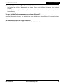
Figure 5.1 Standard Hand Control
UP
POSITION
DOWN
POSITION
LED
WARNING! Do not lean on or apply
downward force to the chair-back when
the lift chair is in the fully reclined
position. Doing so could cause the lift
chair to tip, resulting in personal injury
and/or product damage.
WARNING! Do not use the footrest as a
seat, or for purposes outside its
intended use. Doing so could cause
instability in the lift chair and place
undue stress on lift chair components,
resulting in personal injury and/or
product damage.
WARNING! Lock the hand control when not
in use.
NOTE: As an added safety measure, Pride recommends
that you utilize the quick disconnect to remove the hand
control from the lift chair and store the hand control out
of the reach of children when not in use.

20 www.pridemobility.com Lift Chair Series
LIFT CHAIR SERIES
V. OPERATION
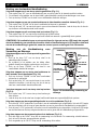
Figure 5.2 Heat and Massage Hand Control
HEAT BUTTON
UP BUTTON
UNLOCK LED
LOCK/UNLOCK
BUTTON
LOCK LED
DOWN BUTTON
MASSAGE
SETTING
LEDS
MASSAGE
BUTTON
INTENSITY
BUTTON
INTENSITY
SETTING LEDS
Heat and Massage Hand Control Operation
Follow these steps to sit in your lift chair (Fig. 5.2):
1. Press and hold the UP button to raise your lift chair to the
standing position.
2. Back into the lift chair and sit in the center of the seat,
using the armrests for support if needed.
3. Press and hold the DOWN button to lower the lift chair
to a comfortable seated position.
Follow these steps to recline your lift chair from the
seated position (Fig. 5.2):
1. Press and hold the DOWN button until comfortably
reclined.
2. Press and hold the UP button to return to an upright,
seated position. Release the button when the lift chair
reaches a comfortable seated position.
Follow these steps to stand up from your lift chair (Fig. 5.2):
1. Press and hold the UP button to raise your lift chair.
2. Release the button when the lift chair reaches a height
where you can stand up comfortably.
Follow these steps to activate/deactivate the lock feature (Fig. 5.2):
1. Press and hold the LOCK button for approximately 3 seconds to lock the hand control. The red LED to
the right of the button will light up to indicate the hand control has been locked.
2. Press and hold the LOCK button for approximately 6 seconds to unlock the hand control. The green LED
to the left of the button will light up to indicate the hand control has been unlocked.
Follow these steps to operate the heat function (Fig. 5.2):
1. Press the HEAT button once to activate the heat function. The heat function will shut off automatically
after 20 minutes of continuous use.
2. Press the HEAT button again to turn off the heat function.
Standard Hand Control Operation
Follow these steps to sit in your lift chair (Fig. 5.1):
1. Engage and hold the up/down switch in the UP position to raise your lift chair to the standing position.
2. Back into the lift chair and sit in the center of the seat, using the armrests for support if needed.
3. Engage and hold the up/down switch in the DOWN position to lower the lift chair to a comfortable seated
position.
Follow these steps to recline your lift chair from the seated position (Fig. 5.1):
1. Engage and hold the up/down switch in the DOWN position until comfortably reclined.
2. Engage and hold the up/down switch in the UP position to return to an upright, seated position. Release
the switch when the lift chair reaches a comfortable seated position.
Follow these steps to stand up from your lift chair (Fig. 5.1):
1. Engage and hold the up/down switch in the UP position to raise your lift chair.
2. Release the switch when the lift chair reaches a height where you can stand up comfortably.
NOTE: The hand control on your lift chair may be equipped with an LED that indicates power to the
hand control. If this LED is present and not lit when the hand control is in use, contact your autho-
rized Pride Provider.
Seite wird geladen ...
Seite wird geladen ...
Seite wird geladen ...
Seite wird geladen ...
Seite wird geladen ...
Seite wird geladen ...
Seite wird geladen ...
Seite wird geladen ...
Seite wird geladen ...
Seite wird geladen ...
Seite wird geladen ...
Seite wird geladen ...
Seite wird geladen ...
Seite wird geladen ...
Seite wird geladen ...
Seite wird geladen ...
Seite wird geladen ...
Seite wird geladen ...
Seite wird geladen ...
Seite wird geladen ...
Seite wird geladen ...
Seite wird geladen ...
Seite wird geladen ...
Seite wird geladen ...
Seite wird geladen ...
Seite wird geladen ...
Seite wird geladen ...
Seite wird geladen ...
Seite wird geladen ...
Seite wird geladen ...
Seite wird geladen ...
Seite wird geladen ...
Seite wird geladen ...
Seite wird geladen ...
Seite wird geladen ...
Seite wird geladen ...
Seite wird geladen ...
Seite wird geladen ...
Seite wird geladen ...
Seite wird geladen ...
Seite wird geladen ...
Seite wird geladen ...
Seite wird geladen ...
Seite wird geladen ...
Seite wird geladen ...
Seite wird geladen ...
Seite wird geladen ...
Seite wird geladen ...
Seite wird geladen ...
Seite wird geladen ...
Seite wird geladen ...
Seite wird geladen ...
Seite wird geladen ...
Seite wird geladen ...
Seite wird geladen ...
Seite wird geladen ...
Seite wird geladen ...
Seite wird geladen ...
Seite wird geladen ...
Seite wird geladen ...
Seite wird geladen ...
Seite wird geladen ...
Seite wird geladen ...
Seite wird geladen ...
Seite wird geladen ...
Seite wird geladen ...
Seite wird geladen ...
Seite wird geladen ...
Seite wird geladen ...
Seite wird geladen ...
Seite wird geladen ...
Seite wird geladen ...
Seite wird geladen ...
Seite wird geladen ...
Seite wird geladen ...
Seite wird geladen ...
Seite wird geladen ...
Seite wird geladen ...
Seite wird geladen ...
Seite wird geladen ...
Seite wird geladen ...
Seite wird geladen ...
Seite wird geladen ...
Seite wird geladen ...
Seite wird geladen ...
Seite wird geladen ...
Seite wird geladen ...
Seite wird geladen ...
Seite wird geladen ...
Seite wird geladen ...
Seite wird geladen ...
Seite wird geladen ...
Seite wird geladen ...
Seite wird geladen ...
Seite wird geladen ...
Seite wird geladen ...
Seite wird geladen ...
Seite wird geladen ...
Seite wird geladen ...
Seite wird geladen ...
Seite wird geladen ...
Seite wird geladen ...
Seite wird geladen ...
Seite wird geladen ...
Seite wird geladen ...
Seite wird geladen ...
Seite wird geladen ...
Seite wird geladen ...
Seite wird geladen ...
Seite wird geladen ...
Seite wird geladen ...
Seite wird geladen ...
Seite wird geladen ...
Seite wird geladen ...
Seite wird geladen ...
Seite wird geladen ...
Seite wird geladen ...
Seite wird geladen ...
Seite wird geladen ...
Seite wird geladen ...
-
 1
1
-
 2
2
-
 3
3
-
 4
4
-
 5
5
-
 6
6
-
 7
7
-
 8
8
-
 9
9
-
 10
10
-
 11
11
-
 12
12
-
 13
13
-
 14
14
-
 15
15
-
 16
16
-
 17
17
-
 18
18
-
 19
19
-
 20
20
-
 21
21
-
 22
22
-
 23
23
-
 24
24
-
 25
25
-
 26
26
-
 27
27
-
 28
28
-
 29
29
-
 30
30
-
 31
31
-
 32
32
-
 33
33
-
 34
34
-
 35
35
-
 36
36
-
 37
37
-
 38
38
-
 39
39
-
 40
40
-
 41
41
-
 42
42
-
 43
43
-
 44
44
-
 45
45
-
 46
46
-
 47
47
-
 48
48
-
 49
49
-
 50
50
-
 51
51
-
 52
52
-
 53
53
-
 54
54
-
 55
55
-
 56
56
-
 57
57
-
 58
58
-
 59
59
-
 60
60
-
 61
61
-
 62
62
-
 63
63
-
 64
64
-
 65
65
-
 66
66
-
 67
67
-
 68
68
-
 69
69
-
 70
70
-
 71
71
-
 72
72
-
 73
73
-
 74
74
-
 75
75
-
 76
76
-
 77
77
-
 78
78
-
 79
79
-
 80
80
-
 81
81
-
 82
82
-
 83
83
-
 84
84
-
 85
85
-
 86
86
-
 87
87
-
 88
88
-
 89
89
-
 90
90
-
 91
91
-
 92
92
-
 93
93
-
 94
94
-
 95
95
-
 96
96
-
 97
97
-
 98
98
-
 99
99
-
 100
100
-
 101
101
-
 102
102
-
 103
103
-
 104
104
-
 105
105
-
 106
106
-
 107
107
-
 108
108
-
 109
109
-
 110
110
-
 111
111
-
 112
112
-
 113
113
-
 114
114
-
 115
115
-
 116
116
-
 117
117
-
 118
118
-
 119
119
-
 120
120
-
 121
121
-
 122
122
-
 123
123
-
 124
124
-
 125
125
-
 126
126
-
 127
127
-
 128
128
-
 129
129
-
 130
130
-
 131
131
-
 132
132
-
 133
133
-
 134
134
-
 135
135
-
 136
136
-
 137
137
-
 138
138
-
 139
139
-
 140
140


Pride 101 Bedienungsanleitung
- Kategorie
- Massagegeräte
- Typ
- Bedienungsanleitung
in anderen Sprachen
- English: Pride 101 Owner's manual
- français: Pride 101 Le manuel du propriétaire
- italiano: Pride 101 Manuale del proprietario
- Nederlands: Pride 101 de handleiding
Andere Dokumente
-
Human Touch ThermoStretch HT-7120 Benutzerhandbuch
-
 Pride Mobility Jazzy Passport Bedienungsanleitung
-
Casada KENNEDY IV Benutzerhandbuch
-
Ideal 700 002 Benutzerhandbuch
-
Vermeiren Ontario I Benutzerhandbuch
-
-
Crivit HG00628B Operation and Safety Notes
-
Quickie IRIS® Bedienungsanleitung
-
Midmark Elevance® Dental Chair Installationsanleitung
-
IRIS ZIPPIE Bedienungsanleitung
