
Issue 1 270722 Page 1
Information for the Product user:
Installation
1. Please note the requirement to dispose of Waste Electrical & Electronic Equipment separately
from household waste (WEEE marked with crossed out wheelie bin symbol).
2. Please consider your role in contributing to re-use and recycling by returning this product at
end of life to a collection centre for waste electrical equipment or a Civic Amenity site, or to a
retail outlet from which you are purchasing a replacement.
3. This equipment may contain substances that are hazardous to health and the environment if
disposed of carelessly. It is important that it is separated from normal household waste and
recycled in the WEEE chain
4. The “crossed out wheelie bin symbol” on a product indicates this equipment must not be
disposed of in normal household waste, but should be disposed of according to local WEEE
regulations
-20°C < Ta < +40°C, DC 24V, Class III, IP67
Suitable for mounting on a normally flammable surface.
-20°C < Ta < +40°C, DC 24V , Klasse III, IP67
Geschikt voor montage op een normaal ontvlambare oppervlake.
-20°C < UT < +40°C, DC 24V , Klasse III, IP67
Geeignet zur Montage auf einer brennbaren Fläche.
Installatie Installation
Informatie voor de gebruiker van het product:
1. Hou bij het verwijderen van afval rekening met de regeling voor afgedankte elektrische en
elektronische apparatuur, gescheiden van gewoon huishoudelijk afval (AEEA, pictogram van
een kliko met een kruis erdoorheen).
2. Neem uw verantwoordelijkheid op het vlak van hergebruik en recycling door dit product aan het
einde van zijn levenscyclus in te leveren bij een inleverpunt voor elektronisch afval, een
milieupark of een winkel waar u een nieuw product koopt.
3. Deze apparatuur kan stoffen bevatten die gevaarlijk zijn voor de gezondheid en het milieu indien
ze onachtzaam wordt weggegooid. Het is belangrijk dat het gescheiden gehouden wordt van het
normaal huishoudelijk afval en gerecycled wordt in het netwerk voor AEEA.
4. Het pictogram van een kliko met een kruis erdoorheen op een product betekent dat dit apparaat
niet samen met het gewone huishoudelijk afval mag worden weggegooid, maar dat het dient te
worden verwijderd in overeenstemming met de lokale regelgeving voor AEEA (afgedankte
elektrische en elektronische apparatuur).
Informationen für den Benutzer:
1. Beachten Sie, dass die Entsorgung von ausgedienten Elektro- und Elektronikgeräten getrennt
vom Hausmüll erfolgen muss (die Geräte sind mit dem Symbol einer durchgestrichenen
Tonne gekennzeichnet).
2. Beachten Sie Ihre Rolle im Wiederverwendungs- und Recycling-Zyklus, indem Sie dieses
Produkt am Ende der Nutzungsdauer bei einer Sammelstelle für Elektronikaltgeräte oder
einer städtischen Müllkippe, oder einer Verkaufsstelle, wo Sie einen Ersatz besorgen,
entsorgen.
3. Dieses Gerät kann Substanzen enthalten, die gesundheits- und umweltschädlich sind, falls
sie achtlos entsorgt werden. Es ist wichtig, dass es vom normalen Hausmüll getrennt und in
der Kette der Elektro-Altgeräte recycelt wird
4. Das „durchgestrichene Tonnen-Symbol“ auf einem Produkt bedeutet, dass dieses Gerät nicht
mit dem normalen Hausmüll, sondern gemäß der Entsorgungsvorschriften für
Elektro-Altgeräte entsorgt werden muss
EN NL DE
VEGAS EXPRESS 14W/M, 12V, LED STRIP
LIGHT, IP67
VEGAS EXPRESS 14W/M, 12V, LED-STRIP
LICHT, IP67
VEGAS EXPRESS 14W/M, 12V,
LED-STREIFENLEUCHTE, IP67
1 Ensure mains supply is switched off before commencing work.
2 If necessary cut LED strip to the required length at the locations marked on the strip
(Every 6 LED’s). Apply the glue to end-cap and push it onto the end of strip. (See cutting and
joining instruction diagram) Note: This strip is IP67 rated. When cut or joined the IP rating
cannot be guaranteed
3 Mounting the Strip:
a. Self adhesive strip: Remove the protective film to reveal adhesive strip. Place the strip
onto the desired location and press down firmly. Ensure the strip is secure. NOTE: only
suitable to use in the following aluminium extrusions (REXP142-23REXR521-23
REXR522-23REXA202-23, REXS212-23, REXR212-23).
b. Clips: Place the strip along the desired position. Mark the locations where the clips are
required, keeping them equally spaced. Fix clips to surface using screws. Check that the
screws will not impinge on concealed cables or pipes.
4 The “start connector” is used to connect power to or join the LED strip. It is marked with
“+” black, red, green, blue and white wires, which will correspond with “+, R, G, B and W on
the LED strip. Connect connector to strip. (See cutting and joining IM). (Note that when the
wire connector is used to connect to RGB+W-AMP or extending the strip the connection
sequence will be reversed on the next connection).
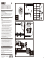
5 Please see installation diagram and choose the most suitable installation method.
Note: When connected in series it is not possible to extend the strip to lengths longer than
5m. However, strips may be connected in parallel up to the max rating of the power supply
used.
6 Connect the strips to the driver (choose the correct driver based on the length of the strip).
If required please use IP box for the connection.
1 Zorg dat het lichtnet is uitgeschakeld voordat u begint.
2 Snijd indien nodig de LED-strip op de gewenste lengte op de gemarkeerde plaatsen op de
strip (om de 6 LEDs). Breng de lijm aan op de eindkap en duw het op het uiteinde van de
strip. (Zie het schema met afsnijd- en verbindingsaanwijzingen). Opmerking: Deze strip heeft
een IP67-veiligheidsklasse. Bij het afsnijden of verbinden kan de IP-klasse niet worden
gewaarborgd
3 De strip monteren:
a. Zelfklevende strip: Verwijder de beschermfolie van de kleefstrook. Plaats de strip
op de gewenste plaats en druk stevig vast. Zorg dat de strip goed vast zit.
OPMERKING: alleen geschikt voor gebruik bij de volgende aluminium profielen
(REXP142-23, REXR521-23, REXR522-23, REXA202-23, REXS212-23, REXR212-23).
b. Klemmen: Plaats de strip op de gewenste positie. Markeer de plaatsen waar klemmen
nodig zijn en zorg voor gelijke tussenafstanden. Bevestig de klemmen tegen het oppervlak
aan de hand van schroeven. Controleer dat de schroeven geen verborgen kabels of
leidingen kunnen beschadigen
4 De “startconnector” wordt gebruikt om de LED-strip van stroom te voorzien of te verbinden.
Deze is gemarkeerd met “+” zwarte, rode, groene, blauwe en witte draden, die
overeenstemmen met “+, R, G, B and W op de LED-strip. Sluit de connector aan op de strip.
(Zie IM afsnijden en verbinden). (Houd er rekening mee dat wanneer de draadconnector
wordt gebruikt voor aansluiting voor aansluiting op RGB+W-AMP of om de strip te verlengen,
de volgorde omgekeerd zal zijn op de volgende aansluiting).
5 Zie het installatieschema en kies de meest geschikte installatiemethode.
Opmerking: Bij seriële aansluiting is het niet mogelijk de strip langer te verlengen dan 5m. De
strips kunnen echter parallel worden aangesloten tot aan het max. vermogen van de
gebruikte stroombron
6 Sluit de strips aan op de driver (kies de juiste driver op basis van de lengte van de strip).
Gelieve indien nodig een IP-doos te gebruiken voor de aansluiting.
1. Vergewissern Sie sich, dass die Stromzufuhr ausgeschaltet ist, bevor Sie mit der Installation
beginnen.
2. Wenn nötig, kürzen Sie die LED-Leiste an den entsprechen Markierungen auf die
gewünschte Länge (alle 6 LEDs). Tragen Sie den Kleber auf die End-Abdeckung auf und
drücken Sie sie gegen das Ende der Leiste. (Siehe Anleitungsdiagramm für Schneiden und
Verbinden.) Hinweis: Die Leiste ist IP67-zertifiziert. Wenn sie gekürzt oder verlängert wird,
kann die IP-Zertifizierung nicht gewährleistet werden.
3. Montage der Leiste:
a. Selbstklebende Leiste: Ziehen Sie die Schutzfolie von der Klebefläche ab. Setzen Sie die
Leiste an die gewünschte Stelle und drücken Sie sie fest an.Achten Sie darauf, dass die
Leiste festsitzt. HINWEIS: Nur zur Verwendung in folgenden Aluminium-Strangpressprofilen
geeignet (REXP142-23, REXR521-23, REXR522-23, REXA202-23, REXS212-23,
REXR212-23).
b. Montageklammern: Legen Sie die Leiste an der gewünschten Stelle an. Zeichnen Sie die
Punkte an, an denen die Clips befestigt werden sollen, achten Sie dabei auf gleichmäßige
Abstände. Befestigen Sie die Clips mithilfe von Schrauben auf der Fläche. Vergewissern Sie
sich, dass die Schrauben keine Rohre oder Leitungen beschädigen.
4. Für den Stromanschluss oder um die LED-Leiste zu verbinden wird das
„Start-Anschlussstück“ verwendet. Es ist mit „+“ schwarzen, roten, grünen, blauen und
weißen Kabeln markiert, die „+“, R, G, B und W auf der LED-Leiste entsprechen. Schließen
Sie das Anschlussstück an die Leiste an. (Siehe Anleitungsdiagramm für Kürzen und
Verbinden.) (Bitte beachten Sie, dass die Reihenfolge der Verbindung bei der nächsten
Verbindung umgekehrt ist, wenn der Kabelanschluss für die Verbindung mit RGB+W-AMP
oder zur Erweiterung der Leiste benutzt wird.)
5. Bitte sehen Sie sich das Installationsdiagramm an und wählen Sie die geeignetste
Installationsmethode. Hinweis: Bei Reihenschaltungen kann die Leiste nicht auf Längen
über 5m erweitert werden. Um die maximale Stromleistung zu nutzen, können die Leisten
aber parallel geschaltet werden.
6. Schließen Sie die Leiste an den Treiber an (verwenden Sie je nach Länge der Leiste den
korrekten Treiber). Wenn erforderlich, verwenden Sie für den Anschluss ein IP-Gehäuse.
1 Pred začetkom dela vključite omrežno napajanje.
2 Po potrebi na na traku označenih mestih odrežite trak LED na želeno dolžino (na vsake
3 LED). Nanesite lepilo na zaključno kapo in jo pritisnite na končni del traku. (Glejte
shemo z navodili za rezanje in spajanje.) Pomni: Ta trak ima stopnjo zaščite IP67. Če
trak odrežete in spojite, stopnja zaščite ni več zajamčena.
3 Namestitev traku:
a. Samolepilni trak: Odstranite zaščitni film z lepilnega traku. Namestite trak na želeno
mesto in ga močno pritisnite dol. Trak mora biti trdno pritrjen. POMNI: Primerno samo za
uporabo z naslednjimi aluminijastimi ekstruzijami (REXP142-23, REXR521-23,
REXR522-23, REXA202-23, REXS212-23, REXR212-23).
b. Sponke: Raztegnite trak ob želenem mestu. Označite mesta, kamor boste namestili
sponke, na enakomeren razmik. Z vijaki pritrdite sponke na površino. Previdno, da z
vijaki ne poškodujete skritih kablov ali cevi.
4 S konektorjem RVA67RGBW-C1 priključite napajanje ali spojite trak LED. Konektor je
označen s + črna, rdeča, zelena, modra in bela žica, ki ustreza +, R, G, B oziroma W na
traku LED. Priključite konektor na trak. (Glejte navodila za rezanje in spajanje). (Pomni:
Če priključite s konektorjem RVA67RGBW-C1 na RGB-W-AMP ali podaljšate trak, bo na
naslednji povezavi zaporedje obrnjeno).
5 Glejte shemo z navodili za napeljavo in izberite najustreznejši način napeljave.
Pomni: Če priključite v vrsti, lahko trak podaljšate na največ 5 m. Vzporedno lahko
trakove priključite do največje nazivne moči uporabljene omrežne napetosti.
6 Priključite trakove na gonilnik (izberite 24 Vgonilnik, ki je primeren za dolžino traku).
Za povezavo uporabite dozo IP.
SL
Inštalacija
-20°C < Ta < +40°C, DC 24V, razred III, IP67
Primerno z a montažo na vnetljivo površino.
Informacije za uporabnika:
1. Upoštevajte predpise o odstranjevanju odpadne električne in elektronske opreme – proizvoda
ni dovoljeno odstraniti med gospodinjske odpadke (OEEO s simbolom: prekrižanim
zabojnikom za odpadke na kolesih).
2. Prispevajte k varovanju okolja in omogočite reciklažo proizvoda – po koncu njegove
življenjske dobe ga predajte pristojnemu zbirnemu centru za odpadke ali vrnite trgovcu, pri
katerem ste ga kupili.
3. Ta oprema lahko vsebuje snovi, ki so v primeru malomarnega ravnanja nevarne za zdravje in
okolje. Pomembno je, da proizvod ločite od drugih gospodinjskih odpadkov in ga predate v
reciklažo (OEEO).
4. Simbol »prekrižani zabojnik za odpadke na kolesih« na proizvodu pomeni, da tega proizvoda
ni dovoljeno odstraniti med običajne gospodinjske odpadke, temveč skladno s predpisi o
OEEO.
VEGAS EXPRESS 14W/M, 12V, SVETILNI
TRAK, IP67
RVARGB3K671
RVARGB3K673
RVARGB3K675
:RGB+White 3000K
:RGB+White 3000K
:RGB+White 3000K
:RGB+White 4000K
:RGB+White 4000K
:RGB+White 4000K
RVARGB4K671
RVARGB4K673
RVARGB4K675
RVARGB3K671
RVARGB3K673
RVARGB3K675
:RGB+Wit 3000K
:RGB+Wit 3000K
:RGB+Wit 3000K
:RGB+Wit 4000K
:RGB+Wit 4000K
:RGB+Wit 4000K
RVARGB4K671
RVARGB4K673
RVARGB4K675
RVARGB3K671
RVARGB3K673
RVARGB3K675
:RGB+Weiß 3000K
:RGB+Weiß 3000K
:RGB+Weiß 3000K
:RGB+Weiß 4000K
:RGB+Weiß 4000K
:RGB+Weiß 4000K
RVARGB4K671
RVARGB4K673
RVARGB4K675
RVARGB3K671
RVARGB3K673
RVARGB3K675
:RGB+Bela 3000K
:RGB+Bela 3000K
:RGB+Bela 3000K
:RGB+Bela 4000K
:RGB+Bela 4000K
:RGB+Bela 4000K
RVARGB4K671
RVARGB4K673
RVARGB4K675
PLEASE READ INSTRUCTION BEFORE COMMENCING INSTALLATION AND RETAIN FOR
FUTURE REFERENCES.
! Electrical products can cause death or injury, or damage to property.
The Installation must
be carried out by a qualified electrician
.
Note:
The luminaire must be disconnected before carrying out any insulation resistance testing.
Product technical information and specification may change over time without prior
notification. For the latest technical information please visit our web site www.robus.com
or robusdirect.com
LEES DE INSTRUCTIES VOORDAT U BEGINT MET DE INSTALLATIE EN HOU ZE BIJ
VOOR LATER.
! Elektrische producten kunnen de dood of letsel veroorzaken of eigendommen
beschadigen.
De installatie dient te worden uitgevoerd door een elektricien
.
Opmerkingen:
De lamp moet worden losgekoppeld voordat de isolatieweerstand wordt getest.
Technische gegevens en specificaties van dit product kunnen zonder voorafgaande
kennisgeving wijzigen. Ga voor de meest recente technische gegevens naar onze website
www.robus.com of robusdirect.com
LESEN SIE DIE ANLEITUNG, BEVOR SIE MIT DER INSTALLATION BEGINNEN, UND
BEWAHREN SIE SIE FÜR DIE SPÄTERE VERWENDUNG AUF.
! Elektronikprodukte können Tod, schwere Verletzungen oder Sachschaden verursachen.
Die Installation muss von einem Elektriker vorgenommen werden
.
Hinweis:
Vor der Durchführung von Isolationswiderstandsprüfungen muss die Leuchte vom Strom
getrennt werden. Technische Produktinformationen und Angaben können sich im Lauf der
Zeit ohne weitere Mitteilung ändern. Besuchen Sie unsere Webseite www.robus.com oder
robusdirect.com für aktuelle technische Informationen.
PRED MONTAŽO SKRBNO PREBERITE NAVODILA ZA UPORABO IN JIH SHRANITE NA
VARNO MESTO, SAJ JIH BOSTE POZNEJEMORDA ŠE POTREBOVALI.
! Električne naprave lahko povzročijo telesne poškodbe, smrt in materialno škodo.
Priklop
sme izvesti le strokovnjak za elektrotehniko
.
Opomba:
Pred preizkusi izolacijske upornosti svetilko obvezno izključite. Pridržujemo si pravico do
sprememb proizvoda in tehničnih specifikacij brez predhodnega obvestila. Za najnovejše
tehnične informacije obiščite našo spletno stran www.robus.com ali robusdirect.com.

-20°C < Ta < +40°C, DC 24V , Classe III, IP67
Approprié pour un montage sur une surface normalement inflammable.
1. Vérifier que l’alimentation électrique est coupée avant de commencer l’installation.
2. Si nécessaire, couper le ruban LED à la longueur désirée à un emplacement marqué sur le ruban.
(à intervalles de 6 LED). Encoller et insérer l’embout à l’extrémité du ruban. (Voir le diagramme
d’instructions de coupe et de jonction). Remarque : le ruban est conforme à la norme IP67. La
conformité IP n’est plus garantie en cas de coupure ou de jonction du ruban.
3 Pose du ruban :
a. Ruban auto-adhésif : ôter le film de protection pour découvrir la bande d’adhésif. Poser le ruban
à l’emplacement désiré et appuyer fermement. Vérifier que le ruban adhère correctement.
REMARQUE : utilisable uniquement dans les profils aluminium suivants (REXP142-23,
REXR521-23, REXR522-23, REXA202-23, REXS212-23, REXR212-23).
b. Clips : poser le ruban à l’emplacement désiré. Marquer les emplacements de pose des clips en
veillant à conserver un espacement régulier. Fixer les clips sur le support à l’aide de vis. Vérifier
que les vis ne touchent pas des câbles ou des tuyauteries enfouies.
4 Le « connecteur de début » permet de connecter l’alimentation ou d’interconnecter les rubans LED.
Le connecteur comprend les fils « + » noir, rouge vert, bleu et blanc qui correspondent
respectivement aux signes « + » et aux lettres R, G, B et W sur le ruban LED. Raccorder le
connecteur au ruban. (Voir le manuel d’instructions de coupe et de jonction). (Noter que la
séquence de connexion est inversée sur la connexion suivante lorsque le connecteur de câble est
utilisé pour la connexion à RGB+W-AMP ou au prolongateur de ruban).
5 Choisir la méthode d’installation la mieux appropriée, à l’aide du diagramme de pose.
Remarque : les connexions en série ne permettent pas d’étendre le ruban au-delà de 5m.
Il est cependant possible de connecter les rubans en parallèle jusqu’à la puissance maximale
autorisée par l’alimentation électrique utilisée.
6 Connecter le ruban au pilote (sélectionner le pilote en fonction de la longueur du ruban).
Si nécessaire utiliser un boîtier de connexion avec protection IP.
IT: AVVERTENZA – I dispositivi elettrici possono causare lesioni gravi o la morte o danneggiare l’apparecchio. In
caso di dubbi sull’installazione o sull’utilizzo di questo prodotto, consultare un elettricista competente.
Assicurarsi che l’alimentazione principale sia spenta prima di effettuare interventi.
EST: HOIATUS! Elektritooted võivad põhjustada surma, raskeid vigastusi või varakahjustusi. Kui teil on toote
paigaldamisel või kasutamisel kahtlusi, küsige nõu asjatundlikult elektrikult. Enne töö alustamist veenduge, et
elektrivool oleks välja lülitatud.
SLK: UPOZORNENIE - Elektrické výrobky môžu spôsobiť smrť, vážne zranenie alebo škodu na majetku. Ak
máte akékoľvek pochybnosti o inštalácii tohto výrobku, poraďte sa s kvalifikovaným elektrikárom. Pred začatím
práce skontrolujte, že je hlavný zdroj
Informations pour l’utilisateur du produit :
Installation
1. Veuillez, s’il vous plait, noter l’importance de disposer des Déchets d’Equipement Electriques et Electroniques
séparément des déchets ménagers (DEEE représenté par une poubelle barrée d’une croix).
2. Veuillez tenir compte de l’importance de votre contribution à la réutilisation et au recyclage de ce produit en
fin de vie en le retournant dans un centre de collecte de déchets des équipements électriques ou dans le
point de vente à partir duquel vous effectuez l’achat du produit de remplacement.
3. Cet équipement peut contenir des substances dangereuses pour la santé et l’environnement s’il est jeté
n’importe où. Il est important de le séparer des ordures ménagères et le recycler dans une consigne DEEE
appropriée.
4. La “poubelle barrée d’une croix” présent sur le produit indique que cet appareil ne doit pas être jeté dans les
ordures ménagères mais doit être éliminé conformément à la réglementation DEEE locale.
L’installation doit être effectuée par un électricien qualié
FR
Tel: +353 1 7099000
Fax: +353 1 7099060
Email: [email protected]
Website: www.robus.com
L.E.D Lighting & Electrical Distribution Group Ltd
IRE: Nangor Road, Dublin 12, D12 E7VP, Ireland
UK: Bracknell Enterprise & Innovation Hub, Ocean
House, 12th Floor, The Ring, Bracknell,
Berkshire RG12 1AX, UK
VEUILLEZ LIRE LES INSTRUCTIONS AVANT DE COMMENCER L’INSTALLATION ET CONSERVEZ-LES POUR
TOUTES UTILISATIONS FUTURES.
Les produits électriques peuvent causer la mort, de graves blessures ou des dégâts matériels.
L’installation
doit être effectuée par un électricien qualifié
.
Remarque :
Le luminaire doit être déconnecté avant d'effectuer tout test de résistance a l’isolation. Les informations
techniques et caractéristiques peuvent changer au fil du temps sans notification préalable. Pour rester
informé de ces possibles modifications, veuillez consulter le site internet www.robus.com ou
robusdirect.com.
1 2
3 4
5
RGB-CTRL & RGB-AMP
DC+
DC-
R/CH1
G/CH2
B/CH3
W/CH4
V+
Driver
RGB+W-CRTL
RGB+W-AMP
Driver
R/CH1
G/CH2
B/CH3
W/CH4
V+
DC+
DC-
V+
R/CH1
G/CH2
B/CH3
W/CH4
Driver
DC+
DC-
R/CH1
G/CH2
B/CH3
W/CH4
V+
RGB+W-CRTL
Page 2
VEGAS EXPRESS 14W/M, 12V, LED STRIP LIGHT, IP67 The clips
RVA67RGBW-EC
RVA67-H
Strip-to-strip without wires
Strip-to-driver with wires
Strip-to-strip with wires
RVA67-G
The end caps
The heat shrinks
The glue
RVARGB3K671
RVARGB3K673
RVARGB3K675
:RGB+Blanc 3000K
:RGB+Blanc 3000K
:RGB+Blanc 3000K
:RGB+Blanc 4000K
:RGB+Blanc 4000K
:RGB+Blanc 4000K
RVARGB4K671
RVARGB4K673
RVARGB4K675
Length
RVARGB3K671 1M
RVARGB3K673 3M
RVARGB3K675 5M
RVARGB4K671 1M
RVARGB4K673 3M
RVARGB4K675 5M
12V +
G
R
B
W
-
 1
1
-
 2
2


Robus RVARGB4K673 Benutzerhandbuch
- Typ
- Benutzerhandbuch
- Dieses Handbuch eignet sich auch für
in anderen Sprachen
- English: Robus RVARGB4K673 User manual
- français: Robus RVARGB4K673 Manuel utilisateur
- Nederlands: Robus RVARGB4K673 Handleiding
- eesti: Robus RVARGB4K673 Kasutusjuhend
Verwandte Artikel
-
Robus RVARGB4K5 Benutzerhandbuch
-
-
-
-
-
-
-
-
-