
DOWNDRAFT VENTILATION
INSTALLATION INSTRUCTIONS
INSTRUCCIONES DE INSTALACIÓN
INSTRUCTIONS D’INSTALLATION
ISTRUZIONI PER L’INSTALLAZIONE
INSTALLATIONSANWEISUNGEN


ENGLISH 4
ESPÃNOL 18
FRANÇAIS 32
ITALIANO 46
DEUTSCH 60
3

As you follow these instruc tions, you will
notice WARNING and CAUTION symbols.
This blocked information is impor tant for the
safe and efficient installation of Wolf equip-
ment. There are two types of potential
hazards that may occur during installation.
Another footnote we would like to identify is
IMPORTANT NOTE: This highlights informa-
tion that is especially relevant to a problem-
free installation.
signals a situation where minor injury or
product damage may occur if you do not
follow instructions.
states a hazard that may cause serious
injury or death if precautions are not
followed.
WOLF
®
is a registered trademark of Wolf Appliance, Inc.
CONTACT
INFORMATION
Website:
wolfappliance.com

INSTALLATION REQUIREMENTS
IMPORTANT NOTE:
This installation must be
completed by a qualified installer or Wolf
authorized service center technician.
Installer:
Please read the entire Installation
Instructions prior to installation. Save these
instructions for the local inspector’s refer-
ence, then leave them with the homeowner.
Homeowner:
Please read and keep these
instructions for future reference and be sure
to read the entire Use & Care Information
prior to use.
Any questions or problems regarding the
installation should be directed to your dealer
or visit our website, wolfappliance.com.
IMPORTANT NOTE:
This appliance must be
installed in accordance with National Electrical
Codes, as well as all state, municipal and local
codes. The correct voltage, frequency and
amperage must be supplied to the appliance
from a dedicated, grounded circuit which is
protected by a properly sized circuit breaker or
time delay fuse. The proper voltage, frequency,
and amperage ratings are listed on the product
rating plate.
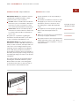
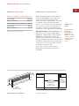
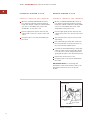
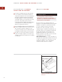
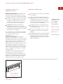
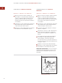
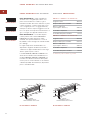
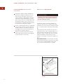
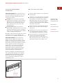
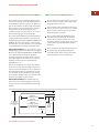
Record the model and serial numbers before
installing the downdraft ventilation system.
Both numbers are listed on the rating plate,
located above the airbox on the front side of
the unit. Refer to the illustration below.
BEFORE YOU START
Proper installation is the responsibility of
the installer.
Check with local utilities for electrical codes
that apply in your area. Local codes vary.
Installation, electrical connections and
grounding must comply with applicable
codes.
This appliance must be properly grounded.
Refer to Electrical Requirements on
page 7.
Make sure you have the tools and materials
necessary for proper installation.
Any required service must be performed by
a Wolf authorized service center. Wolf is not
responsible for service required to correct a
faulty installation.
WOLF DOWNDRAFT VENTILATION SYSTEMS
RATING PLATE
INFORMATION
Model Number
Serial Number
Rating plate location
Location of
rating plate
(behind filters)
5

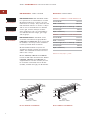
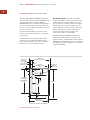
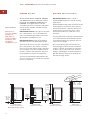
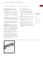
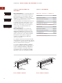
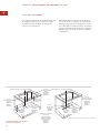
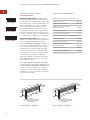
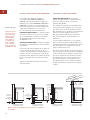
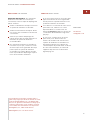
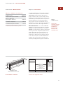
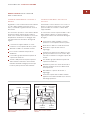
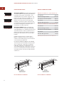
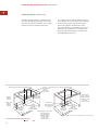
OVERALL DIMENSIONS
MODELS ICBDD30I AND ICBDD30R
Overall Width 762 mm
Width of Chimney 667 mm
Overall Height
(above countertop)
230 mm
Overall Depth 60 mm
Depth of Chimney 38 mm
MODELS ICBDD36I AND ICBDD36R
Overall Width 914 mm
Width of Chimney 819 mm
Overall Height
(above countertop)
230 mm
Overall Depth 60 mm
Depth of Chimney 38 mm
6
WOLF DOWNDRAFT VENTILATION SYSTEMS
DOWNDRAFT VENTILATION
IMPORTANT NOTE:
Wolf downdraft ventila-
tion systems are recommended for use with
Wolf framed induction or electric, gas and
multi-function cooktops. They cannot be used
with unframed induction or electric cooktops
and are not recommended for use with the
electric grill, steamer and fryer modules.
A Pro ventilation hood is recommended for
use with Wolf dual fuel ranges, gas ranges
and rangetops.
IMPORTANT NOTE:
A downdraft can be
used with sealed burner rangetop Models
ICBSRT304 and ICBSRT366. An accessory trim
kit (810215) is necessary for this installation.
Contact your Wolf dealer for details.
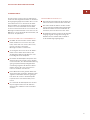
Wolf downdraft ventilation systems are
available in 762 mm, 914 mm and 1156 mm
widths. The downdraft should be at least as
wide as the cooktop.
Models ICBDD30I, ICBDD36I and ICBDD45I
include an 850 m3/hr internal blower. Models
ICBDD30R, ICBDD36R and ICBDD45R are
shipped without a blower assembly and can
be used with a 1529 m3/hr remote blower
(812307), available through your Wolf dealer.
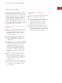
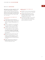
Models ICBDD30I and ICBDD30R
60 mm
762 mm
230 mm
667 mm
38 mm
DEPTH OF
DOWNDRAFT CHIMNEY
914 mm
819 mm
60 mm
230 mm
38 mm
DEPTH OF
DOWNDRAFT CHIMNEY
Models ICBDD36I and ICBDD36R
Model ICBDD30
Model ICBDD36
Model ICBDD45
Dimensions may vary to
+
–
3 mm.

7
INSTALLATION INSTRUCTIONS
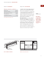
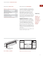
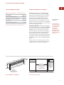
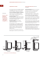
Models ICBDD45I and ICBDD45R
1156 mm
1048 mm
60 mm
230 mm
38 mm
DEPTH OF
DOWNDRAFT CHIMNEY
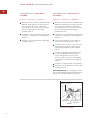
ELECTRICAL REQUIREMENTS
Wolf downdraft ventilation systems require a
separate, 240 V 50/60 Hz power supply. The
service should have its own 10A circuit
breaker. The unit is supplied with a 2.5 m CEE
7/7 “Schuko” style Continental European
power cord. The specific location of the outlet
is not critical, as long as it is within reach of
the power cord that is located mid-way, top
and bottom, on the right side of the downdraft.
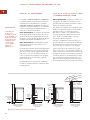
IMPORTANT NOTE:
If Model ICBDD30 is to be
installed in a 762 mm wide cabinet, Model
ICBDD36 in a 914 mm wide cabinet or Model
ICBDD45 in a 1156 mm wide cabinet, the
electrical outlet cannot be located on the back
wall of the cabinet. The outlet can be placed in
an adjacent cabinet within reach of the power
cord. An access hole for the power cord must
be drilled in the cabinet wall.
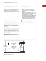
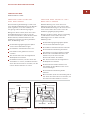
Choose the electrical location shown in
the illustration below that best suits your
installation.
Location of electrical
914 mm min
FOR MODEL ICBDD36
1156 mm min
FOR MODEL ICBDD45
762 mm min
FOR MODEL ICBDD30
OPTIONAL
ELECTRICAL
LOCATION IN
ADJACENT RIGHT
SIDE CABINET
E
OVERALL DIMENSIONS
MODELS ICBDD45I AND ICBDD45R
Overall Width 1156 mm
Width of Chimney 1048 mm
Overall Height
(above countertop)
230 mm
Overall Depth 60 mm
Depth of Chimney 38 mm
Dimensions may vary to
+
–
3 mm.
IMPORTANT
NOTE
You must follow
all National
Electrical Code
regulations. In
addition, be aware
of local codes and
ordinances when
installing your
service.

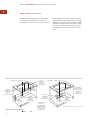
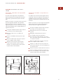
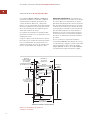
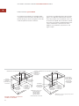
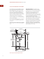
INSTALLATION SPECIFICATIONS
Wolf downdraft Model ICBDD30 will fit most
762 mm wide cabinets, Model ICBDD36 will fit
most 914 mm wide cabinets and Model
ICBDD45 will fit most 1156 mm wide cabinets.
It is recommended that oversized cabinets be
used for easier installation. Cabinet backs may
need to be removed.
Wolf downdraft ventilation systems can be
mounted in an island, peninsula or standard
wall location.
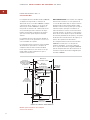
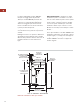
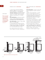
The illustration below provides installation
dimensions for all Wolf downdraft models.
Pay careful attention to the areas of potential
interference as noted in the illustration.
IMPORTANT NOTE:
To install a downdraft
system and a Wolf cooktop, you must allow for
a minimum 638 mm flat counter space from
front to back. A countertop with a raised lip or
backsplash may not allow enough space for
proper installation. 60 mm of flat countertop is
required behind the cooktop and 44 mm is
necessary between the back edge of the
cooktop and inside of cabinet back.
If downdraft Model ICBDD30 is installed in
combination with with two cooktops or inte-
grated modules, an integrated module support
(8603386) for downdraft ventilation is required.
The integrated module support is not required
for Model ICBDD45.
8
WOLF DOWNDRAFT VENTILATION SYSTEMS
54 mm
489 mm
COOKTOP CUT-OUT
DEPTH
914 mm
60 mm
638 mm
min
OF FLAT COUNTERTOP
*
8.7 mm
745 mm
COUNTERTOP
TO BOTTOM OF
AIR BOX
457
mm
92
mm
83 mm
127
mm
197 mm
16 mm
64 mm min
WITH NO
RAISED LIP
*
*
AREAS OF POTENTIAL INTERFERENCE
610 mm min
CABINET DEPTH
44 mm min
BACK EDGE
OF COOKTOP
TO INSIDE OF
CABINET BACK
*
181 mm
Downdraft installation dimensions

9
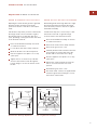
INSTALLATION INSTRUCTIONS
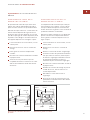
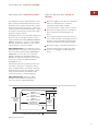
INSTALLATION SPECIFICATIONS
For installation of a downdraft system with a
cooktop, refer to the cooktop installation
instructions for the dimensions of the cooktop,
countertop cut-out and cabinet requirements.
The depth of the cooktop may vary and will
affect the location of the downdraft in the
countertop.
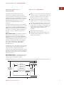
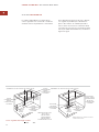
The illustration below provides countertop
cut-out dimensions for downdraft Models
ICBDD30, ICBDD36 and ICBDD45 installed with
a Wolf 762 mm or 914 mm cooktop or combi-
nation of cooktop and/or modules.
IMPORTANT NOTE:
For installation of a
downdraft with sealed burner rangetop
Models ICBSRT304 and ICBSRT366, an acces-
sory trim kit (810215) is necessary. Contact
your Wolf dealer for details. To obtain local
dealer information, visit our website, wolfap-
pliance.com.
The control module can be positioned horizon-
tally or vertically and located anywhere within
3 m of the downdraft assembly and a
minimum of 76 mm from edge of cooktop cut-
out. Refer to page 11 for instructions to install
the control module.
IMPORTANT NOTE:
The downdraft must be
used with a Wolf-approved control module and
top cover.
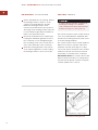
COUNTERTOP CUT-OUT
Layout and cut the cooktop cut-out far
enough forward so the downdraft will fit
behind it.
Set the cooktop in place and slide it as far
forward as possible. Center and square the
cooktop with edges of countertop.
Place the plastic template included with the
downdraft against the back flange of the
cooktop and centered. Trace around the
template to mark the downdraft opening.
Remove the cooktop from countertop.
Cut the downdraft opening. Be careful not
to chip the edges of the countertop.
686 mm
FOR MODEL ICBDD30
838 mm
FOR MODEL ICBDD36
1067 mm
FOR MODEL ICBDD45
64 mm min
76 mm
min FOR
CONTROL
MODULE
COOKTOP CUT-OUT
WIDTH
638 mm min
FLAT
COUNTERTOP
SPACE
489 mm
70 mm
COUNTERTOP TOP VIEW
Countertop cut-out dimensions

WOLF DOWNDRAFT VENTILATION SYSTEMS
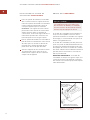
leveling bracket – flange facing in
leveling bracket –
flange facing out
mounting screws
Downdraft mounting brackets
CONTROL MODULE
The remote-mounted control module and top
cover are included with the downdraft. Also
included are mounting brackets, RJ45 connec-
tor and mounting hardware.
The control module can be located anywhere
within reach of the 3 m power cable and a
minimum of 76 mm from edge of cooktop
cut-out. The remote-mounted control module
is 60 mm x 168 mm and can be positioned
horizontally or vertically in the countertop.
IMPORTANT NOTE:
Do not place the module
where it will be in the way of cooking, where
hot pans may be placed or where hot liquids
could be spilled on the controls.
To reduce the risk of burns or ignition of
clothing by reaching across burners,
control module must be mounted at least
76 mm from edge of cooktop cut-out.
DOWNDRAFT INSTALLATION
Set the downdraft into the opening. Extend
the leveling brackets to the floor of the
cabinet so the downdraft sits straight.
NOTE: The leveling brackets can be
removed and reattached in other positions.
The flange of the leveling bracket may have
to face inward in tight cabinet installations.
Refer to the illustration below.
Secure the downdraft to the countertop by
holding the downdraft against the back of
the countertop cut-out and tightening the
two mounting screws (one on each end of
unit) on the underside of the countertop.
Screw the leveling brackets to the bottom
of the cabinet. Tighten the screws holding
the leveling brackets to unit on each side.
10

INSTALLATION INSTRUCTIONS
CONTROL MODULE CONNECTION
Connect the RJ45 connector cable to the back
side of the remote-mounted control
module.
Connect the other end of the cable to the
electrical connection located on the right
side of downdraft assembly. Make sure that
all connections are tight.
Refer to the illustration placed on the front
of the downdraft for the correct orientation
of the RJ45 connector during installation
into the downdraft assembly.
CONTROL MODULE
You will be required to drill three holes and
connect the control module to the downdraft
assembly using the cable provided. A 25 mm
diameter hole for the RJ45 connector cable will
be centered horizontally and vertically in the
back side of the control module. Two 6 mm
diameter holes for the mounting screws will be
located 51 mm from the center of the RJ45
connector cable hole, one on each side.
CONTROL MODULE INSTALLATION
Mark the center of the control module on
the counter top. Measure 51 mm up (or left)
and 51 mm down (or right) to locate holes
for the mounting screws.
Carefully drill the three holes through the
countertop. Be careful not to damage or
chip the countertop surface while drilling.
Check the countertop thickness. Set the
control module in place and make sure the
threaded studs are long enough to allow
the nylon thumbnuts to fully engage.
Thicker countertops may require that the
holes be partially counter-sunk from below.
Apply a bead of caulk all the way around
the underside of the control module to
prevent liquids from reaching the electrical
connection or dripping through the holes in
the countertop. Position the control module.
From below the countertop, thread the two
nylon thumbnuts onto the studs of the
control module and hand tighten only.
11

WOLF DOWNDRAFT VENTILATION SYSTEMS
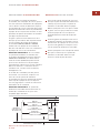
DUCTING CONSIDERATIONS
IMPORTANT NOTE:
Always consult a
qualified HVAC Engineer for specific ducting
applications.
Wolf downdraft models with an internal blower
are designed for use with 83 mm x 254 mm
ductwork and 83 mm x 356 mm ductwork for
models with a remote blower. Each can be
transitioned to 203 mm or 254 mm round
ductwork.
For best performance, 254 mm round ductwork
is recommended. The downdraft will operate
most efficiently when the ductwork does not
exceed 12 m in length.
Choose the ducting option that allows the
shortest length of ductwork and a minimum
number of elbows and transitions. Check the
location of floor joists, wall studs, electrical
wiring or plumbing for possible interference
with the ductwork. Refer to the illustrations
below for ducting options.
305 mm
MIN TO
GROUND
WALL CAP
INTERNAL BLOWER
INSTALLATION THROUGH WALL
Downdraft ducting options
305 mm
MIN TO
GROUND
INTERNAL BLOWER
INSTALLATION THROUGH WALL
305 mm
MIN TO
GROUND
254 mm
ROUND
REMOTE BLOWER
INSTALLATION THROUGH WALL
REMOTE
BLOWER
REMOTE BLOWER
ROOF MOUNT INSTALLATION
REMOTE
BLOWER
254 mm
ROUND
BLOWER OPTIONS
Wolf downdraft Models ICBDD30I, ICBDD36I
and ICBDD45I include an 850 m3/hr internal
blower. Models ICBDD30R, ICBDD36R and
ICBDD45R are shipped without a blower
assembly and can be used with a 1529 m3/hr
remote blower (812307), available through
your Wolf dealer.
IMPORTANT NOTE:
Blower options vary with
the cooking surface. For recommendations,
refer to the Wolf Design Guide found on the
Wolf website, wolfappliance.com.
IMPORTANT NOTE:
Install this downdraft
ventilation system only with a Wolf blower.
The blower will vary in size and is dictated by
the cooking surface, the volume of air that
needs to be moved and the length of the duct
run. A straight, short duct run with a limited
number of elbows and transitions will allow
the downdraft to perform most efficiently.
A remote-mounted blower will minimize the
amount of blower noise, but will not eliminate
the noise completely.
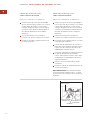
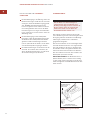
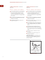
ACCESSORIES
Optional acces-
sories are available
through your
Wolf dealer. To
obtain local dealer
information, visit
our website,
wolfappliance.com.
12

INSTALLATION INSTRUCTIONS
IMPORTANT NOTE:
For installations where
the ductwork is riveted to the unit, an 83 mm x
254 mm collar is provided for models with an
internal blower and an 83 mm x 356 mm collar
is provided for models with a remote blower.
This will allow the blower to be removed and
replaced easily for service without disturbing
the ductwork.
IMPORTANT NOTE:
Use duct tape to seal the
connection between the blower outlet and
ductwork. Support the weight of the ductwork
as necessary to ensure sealed joints.
DUCTWORK INSTALLATION
IMPORTANT NOTE:
Wolf ventilation down-
draft systems must be vented to the outside.
IMPORTANT NOTE:
Before cutting the hole in
the cabinet for ductwork, check for interference
with floor joists, wall studs, electrical wiring or
plumbing.
Cut the hole in the cabinet as well as holes
in wall or floor as necessary for the
ductwork.
Mount the roof or wall cap and work back
towards the cabinet, attaching all ductwork,
elbows and transitions as previously
planned. Tape all ductwork connections to
make them secure and air tight.
Connect the ductwork and transition (if
required) to the downdraft. If necessary,
loosen the nuts and screws that hold the
blower in place, and slide the blower left or
right to align with the ductwork. Retighten
the screws and nuts.
To reduce the risk of fire, use only metal
ductwork.
13

WOLF DOWNDRAFT VENTILATION SYSTEMS
ADJUSTABLE DISCHARGE
Wolf downdraft systems have an adjustable
discharge that will allow you to negotiate
ducting around floor joists and other obstacles.
DISCHARGE CUT-OUT
DIMENSIONS:
260 mm x 89 mm
INTERNAL BLOWER
362 mm x 89 mm
IN-LINE OR
REMOTE BLOWER
CENTERLINE OF COUNTERTOP CUT-OUT
416 mm
INTERNAL BLOWER
546 mm
IN-LINE OR
REMOTE BLOWER
140 mm
INTERNAL BLOWER
108 mm
IN-LINE OR
REMOTE BLOWER
C
L
562 mm
INTERNAL BLOWER
483 mm
IN-LINE OR
REMOTE BLOWER
RIGHT
DISCHARGE
LOCATION
LEFT
DISCHARGE
LOCATION
CENTERLINE OF COUNTERTOP CUT-OUT
362 mm x 89 mm
IN-LINE OR
REMOTE BLOWER
CENTERLINE OF COUNTERTOP CUT-OUT
140 mm
INTERNAL BLOWER
108 mm
IN-LINE OR
REMOTE BLOWER
C
L
NOTE: Measurements are to centerline of duct cut-outs
ADJUSTMENT:
127 mm MAX
IN-LINE OR
REMOTE BLOWER
ADJUSTMENT:
25 mm – 178 mm
INTERNAL BLOWER
165 mm MAX
IN-LINE OR
REMOTE BLOWER
BOTTOM
DISCHARGE
LOCATION
Downdraft adjustable discharge
Three different discharge locations are avail-
able with side-to-side adjustment for accurate
alignment of ductwork. The blower is shipped
with the discharge facing down. Refer to the
illustration below for the discharge location
and adjustment that best suits your installa-
tion.
14

INSTALLATION INSTRUCTIONS
bottom
flange
clamp
channel
nuts
sheet metal
screw
blower
cover plate
clamp
channel
nut
sheet metal
screw
blower
motor plug
Down blower discharge adjustment Left or right blower discharge
ADJUSTING BLOWER DISCHARGE
DOWN DISCHARGE LEFT TO RIGHT
Adjusting the down discharge left to right will
keep the blower discharge in the down
position but allows some side-to-side adjust-
ment.
Follow these steps if the position of the blower
discharge needs to be moved left to right so
that ductwork does not interfere with floor
joists, plumbing or wiring below the unit. Refer
to the illustration below.
Place the downdraft assembly on its back
on a flat work surface.
Loosen the 4 nuts and 2 clamp channels.
Slide the blower to the desired position.
Use the supplied cover plate to close any
open space.
Tighten nuts to secure the top of blower
and use sheet metal screws through the
bottom flange to secure the bottom of the
blower.
DOWN TO LEFT OR RIGHT DISCHARGE
Substituting down discharge with left or right
discharge will switch the blower discharge
from the down position to the left or right of
downdraft assembly.
Follow these steps if it is necessary to rotate
the blower to the left or right discharge
location. Refer to the illustration below.
Place the downdraft assembly on its back
on a flat work surface.
Remove the 4 nuts and 2 clamp channels.
Remove the gear motor cover.
Carefully lift the blower and disconnect the
motor plug if necessary. Reposition the
blower and reconnect the motor plug.
Use the supplied cover plate to close any
open space.
Replace the clamp channels and use the
nuts to secure the blower in its new
position.
Reinstall the gear motor cover.
Use sheet metal screws (not supplied with
unit) through the bottom flange to secure
the bottom of the blower.
15

16
WOLF DOWNDRAFT VENTILATION SYSTEMS
INTERNAL BLOWER WIRING
ICBDD30I, ICBDD36I AND ICBDD45I
Mount a standard 220-240 V AC electrical
box, with 3-pronged grounded receptacle,
inside the cabinet or adjacent cabinet. Make
sure it is located within the reach of the
downdraft’s 2.5 m power cord.
Run the appropriate power cable into the
cabinet and connect it to electrical box and
outlet.
Plug the power cord of the downdraft into
the outlet.
brown to brown
blue to blue
green/yellow to
green/yellow
220-240 V AC
line in
Wiring connections
REMOTE BLOWER WIRING
ICBDD30R, ICBDD36R AND ICBDD45R
Mount a standard 220-240 V AC electrical
box, with 3-pronged grounded receptacle,
inside the cabinet or adjacent cabinet. Make
sure it is located within the reach of the
downdraft’s 2.5 m power cord.
Run the appropriate power cable into the
cabinet and connect it to electrical box and
outlet.
The remote blower may not exceed a 3.0
amp rating.
Run 2-wire plus ground power cable from
the remote blower to the electrical box on
the remote blower adapter plate.
Connect the downdraft wiring to the power
cable from the remote blower. Wire brown
to brown, blue to blue and green/yellow to
green/yellow. Refer to the illustration below.
Replace the electrical box cover.
Plug the power cord of the downdraft into
the outlet.
IMPORTANT NOTE:
For mounting and
installation of the remote blower, refer to the
installation instructions for your specific
blower.

17
TROUBLESHOOTING
IMPORTANT NOTE:
If the downdraft ventila-
tion system does not operate properly, follow
these troubleshooting steps:
Verify that power is being supplied to the
downdraft.
Check electrical connections to ensure that
the installation has been completed
correctly.
Refer to the Troubleshooting Guide in the
Wolf Downdraft Ventilation Use & Care
Information.
If the downdraft still does not work, contact
a Wolf authorized service center. Do not
attempt to repair the downdraft yourself.
Wolf is not responsible for service required
to correct a faulty installation.
IF YOU NEED SERVICE
Maintain the quality built into your down-
draft ventilation system by calling a Wolf
authorized service center.
For service in your area, contact your
Wolf dealer or visit our website,
wolfappliance.com
to find the regional
distributor by country.
When calling for service, you will need the
model and serial number of your down-
draft. This information is found on the
product rating plate, located above the
airbox on the front side of the unit. Refer to
the illustration on page 5.
The information and images in this book are the
copyright property of Wolf Appliance, Inc., an
affiliate of Sub-Zero, Inc. Neither this book nor any
information or images contained herein may be
copied or used in whole or in part without the
express written permission of Wolf Appliance, Inc.,
an affiliate of Sub-Zero, Inc.
©Wolf Appliance, Inc. all rights reserved.
CONTACT
INFORMATION
Website:
wolfappliance.com
INSTALLATION INSTRUCTIONS

Cuando consulte las instrucciones que aparecen
en esta guía, encontrará símbolos de ADVER-
TENCIA y PRECAUCIÓN. Esta información en
recuadros es importante para instalar el equipo
de Wolf de forma segura y eficaz. Existen dos
tipos de posibles riesgos que pueden producirse
durante una instalación.
Otro tipo de anotación que es importante
resaltar es la que se incluye en NOTA IMPOR-
TANTE: En esta nota se resalta la información
que resulta especialmente importante para que
la instalación se realice sin problemas.
indica una situación en la que se pueden
sufrir heridas leves o provocar daños secun-
darios al producto si no se siguen las
instrucciones.
indica peligro de que se produzcan heridas
personales graves o incluso puede provocar
la muerte si no se siguen las precauciones
especificadas.
WOLF
®
es una marca comercial registrada de Wolf Appliance, Inc.
INFORMACIÓN
DE CONTACTO
Página Web:
wolfappliance.com

REQUISITOS DE INSTALACIÓN
NOTA IMPORTANTE:
Esta instalación debe ser
realizada por un técnico cualificado o por un
técnico de mantenimiento autorizado de Wolf.
Instalador:
Lea las instrucciones de insta-
lación antes de llevar a cabo la instalación.
Guarde estas instrucciones para que el inspec-
tor local pueda utilizarlas como referencia y, a
continuación, entréguelas al propietario del
aparato.
Propietario:
Lea y guarde estas instrucciones
para que pueda utilizarlas como referencia en
el futuro y asegúrese de leer la guía de uso y
mantenimiento antes de utilizar el aparato.
Si tiene alguna pregunta o problema relacionado
con la instalación, debe ponerse en contacto con
su distribuidor o visite nuestra página Web
wolfappliance.com.
NOTA IMPORTANTE:
Este aparato debe insta-
larse siguiendo las normativas y reglamentos
nacionales vigentes sobre instalaciones eléctricas
así como todos los reglamentos estatales, munici-
pales y nacionales. Se debe aplicar al aparato el
voltaje, la frecuencia y el amperaje adecuados
desde una instalación eléctrica resistente con
toma de tierra protegida por un fusible de
retardo. El voltaje, la frecuencia y el amperaje se
muestran en la placa de datos del producto.
Apunte la referencia del modelo y los números de
serie antes de instalar la campana extractora de
encimera. Esta información se encuentra en la
placa de datos del producto que está situada en
la caja de aire de la parte delantera de la unidad.
Observe la siguiente ilustración.
ANTES DE COMENZAR
Llevar a cabo una instalación correcta es
responsabilidad del instalador.
Consulte la normativa eléctrica correspon-
diente a su área con los servicios públicos
locales. La normativa local puede variar. La
instalación, las conexiones eléctricas y la
conexión a tierra deben cumplir la normativa
aplicable.
Este aparato debe estar conectado a tierra de
manera correcta. Consulte la sección Requisi-
tos eléctricos en la página 21.
Compruebe que tiene las herramientas y los
materiales necesarios para realizar la insta-
lación de manera correcta.
Cualquier tarea de mantenimiento debe ser
realizada por un centro de asistencia técnica
autorizado de Wolf. Wolf no se hace respon-
sable de las tareas de mantenimiento que
deban realizarse para corregir una instalación
defectuosa.
CAMPANAS EXTRACTORAS DE ENCIMERA DE WOLF
INFORMACIÓN
DE LA PLACA
DE DATOS
Referencia del
modelo
Número de serie
Ubicación de la placa de datos
Ubicación de la placa
de datos (detrás de los filtros)
19

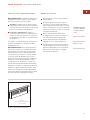
MEDIDAS GENERALES
MODELOS ICBDD30I E ICBDD30R
Anchura total 762 mm
Anchura de chimenea 667 mm
Altura total
(sobre encimera)
230 mm
Profundidad total 60 mm
Profundidad de chimenea 38 mm
MODELOS ICBDD36I E ICBDD36R
Anchura total 914 mm
Anchura de chimenea 819 mm
Altura total
(sobre encimera)
230 mm
Profundidad total 60 mm
Profundidad de chimenea 38 mm
CAMPANAS
EXTRACTORAS DE ENCIMERA DE WOLF
CAMPANA
EXTRACTORA DE
ENCIMERA
NOTA IMPORTANTE:
Se recomienda utilizar las
campanas extractoras de encimera de Wolf con
placas de inducción, vitrocerámicas, placas de
gas y placas multifunción con marco. Estas
campanas no se puede utilizar con vitrocerámicas
o placas de inducción sin marco y no se
recomienda utilizar esta campana extractora con
los módulos de freidora, vaporizador ni con el
módulo de parrilla eléctrico. Para las cocinas
mixtas, las cocinas de gas y las encimeras de
cocción a gas se recomienda utilizar una
campana extractora Pro.
NOTA IMPORTANTE:
Con la encimera de
cocción con quemadores herméticos modelo
ICBSRT304 e ICBSRT366 se puede utilizar una
campana extractora de encimera. Es necesario
utilizar un kit de marco para campana (810215)
para realizar esta instalación. Póngase en
contacto con su distribuidor de Wolf para
obtener más detalles.
Las campanas extractoras de encimera de Wolf
están disponibles en anchos de 762 mm, 914 mm
y 1.156 mm. La campana extractora debe tener al
menos la misma anchura que la placa.
Los modelos ICBDD30I, ICBDD36I e ICBDD45I
incluyen un ventilador interno de 850 m3/hr. Los
modelos ICBDD30R, ICBDD36R e ICBDD45R se
envían sin ventilador y se pueden utilizar con
un ventilador remoto de 1.529 m3/hr (812307)
disponible a través de su distribuidor de Wolf.
Modelos ICBDD30I e ICBDD30R
60 mm
762 mm
230 mm
667 mm
38 mm
PROFUNDIDAD DE
CHIMENEA DE CAMPANA
914 mm
819 mm
60 mm
230 mm
38 mm
PROFUNDIDAD DE
CHIMENEA DE CAMPANA
Modelos ICBDD36I e ICBDD36R
Modelo ICBDD30
Modelo ICBDD36
Modelo ICBDD45
Las medidas pueden variar
+
–
3 mm.
20
Seite wird geladen ...
Seite wird geladen ...
Seite wird geladen ...
Seite wird geladen ...
Seite wird geladen ...
Seite wird geladen ...
Seite wird geladen ...
Seite wird geladen ...
Seite wird geladen ...
Seite wird geladen ...
Seite wird geladen ...
Seite wird geladen ...
Seite wird geladen ...
Seite wird geladen ...
Seite wird geladen ...
Seite wird geladen ...
Seite wird geladen ...
Seite wird geladen ...
Seite wird geladen ...
Seite wird geladen ...
Seite wird geladen ...
Seite wird geladen ...
Seite wird geladen ...
Seite wird geladen ...
Seite wird geladen ...
Seite wird geladen ...
Seite wird geladen ...
Seite wird geladen ...
Seite wird geladen ...
Seite wird geladen ...
Seite wird geladen ...
Seite wird geladen ...
Seite wird geladen ...
Seite wird geladen ...
Seite wird geladen ...
Seite wird geladen ...
Seite wird geladen ...
Seite wird geladen ...
Seite wird geladen ...
Seite wird geladen ...
Seite wird geladen ...
Seite wird geladen ...
Seite wird geladen ...
Seite wird geladen ...
Seite wird geladen ...
Seite wird geladen ...
Seite wird geladen ...
Seite wird geladen ...
Seite wird geladen ...
Seite wird geladen ...
Seite wird geladen ...
Seite wird geladen ...
Seite wird geladen ...
Seite wird geladen ...
-
 1
1
-
 2
2
-
 3
3
-
 4
4
-
 5
5
-
 6
6
-
 7
7
-
 8
8
-
 9
9
-
 10
10
-
 11
11
-
 12
12
-
 13
13
-
 14
14
-
 15
15
-
 16
16
-
 17
17
-
 18
18
-
 19
19
-
 20
20
-
 21
21
-
 22
22
-
 23
23
-
 24
24
-
 25
25
-
 26
26
-
 27
27
-
 28
28
-
 29
29
-
 30
30
-
 31
31
-
 32
32
-
 33
33
-
 34
34
-
 35
35
-
 36
36
-
 37
37
-
 38
38
-
 39
39
-
 40
40
-
 41
41
-
 42
42
-
 43
43
-
 44
44
-
 45
45
-
 46
46
-
 47
47
-
 48
48
-
 49
49
-
 50
50
-
 51
51
-
 52
52
-
 53
53
-
 54
54
-
 55
55
-
 56
56
-
 57
57
-
 58
58
-
 59
59
-
 60
60
-
 61
61
-
 62
62
-
 63
63
-
 64
64
-
 65
65
-
 66
66
-
 67
67
-
 68
68
-
 69
69
-
 70
70
-
 71
71
-
 72
72
-
 73
73
-
 74
74


in anderen Sprachen
- français: Wolf ICBDD30R Manuel utilisateur
- español: Wolf ICBDD30R Manual de usuario
- italiano: Wolf ICBDD30R Manuale utente
Verwandte Artikel
-
Wolf ICBDD45 Installationsanleitung
-
Wolf ICBDD36 Benutzerhandbuch
-
-
-
-
-
-
Wolf ICBCT30IU Benutzerhandbuch
-
-
