D+H KNX-Modbus RTU Gateway 886 Bedienungsanleitung

Typ
Bedienungsanleitung
99.828.10 1.3/01/24 1/2
Deutsch / English
Anwendungsbeispiel / Example for Application
Safety notes
- Connection must be carried out by a certified electrical technician!
- Operating voltage 12 ... 24 V DC!
- Use only in dry rooms
- Use unmodified original D+H parts only.
- Observe the control panel instructions for use.
Sicherheitshinweise
- Anschluss darf nur durch eine autorisierte Elektrofachkraft erfolgen!
- Betriebsspannung 12 ... 24 V DC!
- Nur in trockenen Räumen verwenden.
- Nur unveränderte D+H-Originalteile verwenden.
- Gebrauchsanleitung der Zentrale beachten.
Technische Daten
Typ : KNX Modbus RTU Gateway 886
Versorgung : 12 ... 24 V DC ± 15%, 5 mA
Restwelligkeit : < 10%
KNX-Versorgung : 4 mA
Dateneingang : Modbus RTU
Datenausgang : KNX
Schutzart : IP 20
Temp. Bereich : -5 ... +45 °C
Rel. Feuchte : 5 ... 93 %, nicht kondensierend
Gehäuse : Kunststoff
Abmessungen : 18 x 98 x 71 mm BxHxT
KNX Modbus RTU Gateway 886
Bestimmungsgemäße Verwendung
- Kompaktes KNX/Modbus Gateway mit 250 frei konfigurierbaren
Kanälen (KNX-Datenpunkte)
- Einsetzbar als Modbus-Main (Client). Steuerung von bis zu 25 Subs
(Server).
- Anbindung an andere Gewerke wie GLT über KNX möglich
- Direkte Anbindung von bis zu 25 D+H-ACB-Antrieben möglich.
- Zuordnung zwischen KNX-Objekten und Modbus-Registern direkt in
der ETS (Engineering Tool Software). Kein weiteres Tool erforderlich.
- Einfacher Import des AdComNet Projektabbildes aus der D+H Software
SCS in die ETS-Software
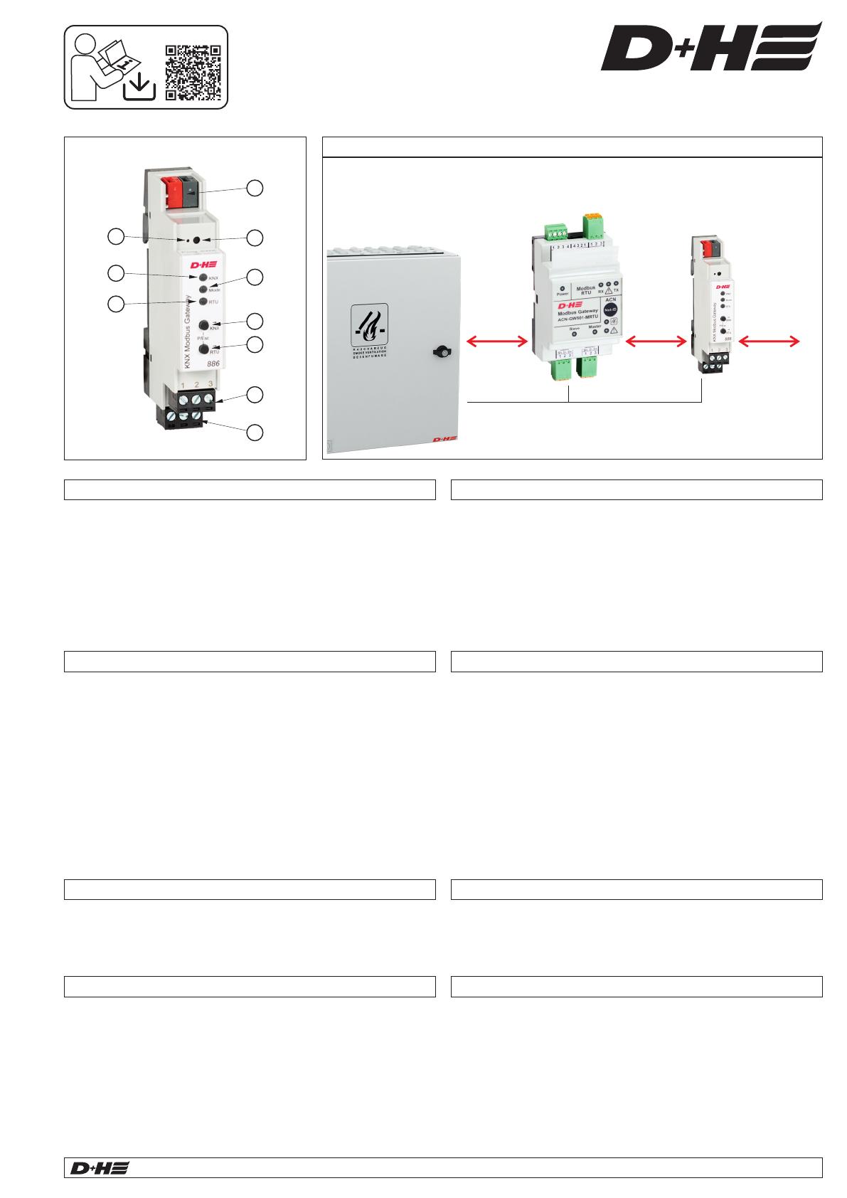
- Für eine Anbindung an AdComNet (z.B. CPS-M1) ist das ACN-GW501-
MRTU-0200 Gateway notwendig
- Der KNX Bus und Modbus sind galvanisch voneinander getrennt.
- Zwei Taster und drei LEDs ermöglichen eine lokale Bedienung und eine
Visualisierung des Gerätezustands
KNX
24 V DC
ACN
Intended use
- Compact KNX/Modbus gateway with 250 freely configurable channels
(KNX data points)
- Can be used as (Client). Control of up to 25 subs Modbus main
(Server).
- Connection to other fields such as BMS via KNX possible
- Direct connection of up to 25 D+H ACB drives possible
- Assignment between KNX objects and Modbus registers directly in the
ETS (Engineering Tool Software). No additional tool required.
- Easy import of the AdComNet project image from the SCS into the ETS
software
- The ACN-GW501-MRTU-0200 Gateway is required for a connection to
the AdComNet (e.g. CPS-M1)
- The gateway provides a galvanic isolation between KNX bus and Modbus.
- Two buttons and three LEDs allow local operation and visualization of
the device status.
Technical Data
Type : KNX Modbus RTU Gateway 886
Power supply : 12 ... 24 V DC ± 15%, 5 mA
Ripple : < 10%
KNX supply : 4 mA
Data input : Modbus RTU
Data output : KNX
Ingress protection : IP 20
Temp. range : -5 ... +45 °C
Ambient humidity : 5 ... 93 %, not condensing
Housing : plastic
Dimensions : 18 x 98 x 71 mm WxHxD
RTU
Modbus Gateway
ACN-GW501-MRTU
KNX Modbus
RTU Gateway 886
CPS-M1 /
AdComNet
control panel
Advanced
Communication
Network Modbus
Bedienelemente und Anzeigen
À KNX Bus Anschluss
Á Programmier-LED
 Taster für Programmiermodus
à LED KNX (mehrfarbig)
Ä LED Mode (mehrfarbig)
Å LED RTU (mehrfarbig)
Æ Taster KNX
Ç Taster RTU
È Anschluss Versorgungsspannung, steckbar (0,34 ... 2,5 mm²)
É Anschluss Modbus, steckbar (0,34 ... 2,5 mm²)
Controls and displays
À KNX bus connector
Á Programming LED
 Button for programming mode
à LED KNX (multicolor)
Ä LED Mode (multicolor)
Å LED RTU (multicolor)
Æ Button KNX
Ç Button RTU
È Power supply connection, pluggable (0,34 ... 2,5 mm²)
É Modbus connection, pluggable (0,34 ... 2,5 mm²)
Originalanleitung
Original instructions
D+H Downloads
ÀÁÂÃÄÅÆÇ
ÈÉ
1
23
45
6
7
8
9
10
99.828.10 1.3/01/24
KNX Programmiermodus
Der KNX Programmiermodus wird über den versenkten KNX-
Programmiertaster oder über gleichzeitigen Druck der Tasten und  Æ
Ç ein- bzw. ausgeschaltet. Die Bedienung des Programmiermodus an
der Front kann in der ETS® mit Prog. Modus an Gerätefront de-/aktiviert
werden. Bei aktivem Programmiermodus leuchten Programmier-LED Á
und LED Mode rot.Ä
Handbedienung und Statusanzeige
Die LED Mode leuchtet oder blinkt bei vorhandener KNX Ä
Busspannung.
Durch langes Betätigen von Taster KNX wird die Synchronisation der Æ
KNX Objekte ausgelöst. Dies wird durch Leuchten der LED Mode in Ä
orange angezeigt.
Durch langes Betätigen von Taster RTU wird die Synchronisation der Ç
Modbus Register ausgelöst. Dies wird durch Leuchten der LED Mode Ä
in orange angezeigt.
Die LED KNX dient zur Statusanzeige der KNX Kommunikation. Sie Ã
blinkt beim Senden und Empfangen von Telegrammen.
Die LED RTU dient zur Status anzeige der Modbus Kommunikation. Å
Sie blinkt beim Senden und Empfangen von Telegrammen.
Zusammenfassung der Zustände der LED Mode :Ä
Inbetriebnahme
LED Verhalten
Bedeutung
LED leuchtet grün
Das Gerät arbeitet im normalen Betriebsmodus.
LED leuchtet rot
Der Programmiermodus ist aktiv.
LED leuchtet
orange
Der Programmiermodus ist nicht aktiv. Die
Synchronisation ist aktiv.
LED blinkt rot
Der Programmiermodus ist nicht aktiv. Die
Synchronisation ist nicht aktiv. Das Gerät ist nicht
korrekt geladen, z.B. nach Abbruch eines Downloads.
LED blinkt grün
Das Gerät befindet sich gerade im ETS Download.
KNX programming mode
The KNX programming mode is activated/deactivated either by pressing
the flushed KNX programming button or by simultaneously pressing Â
the buttons and . The operation of the programming mode at the Æ Ç
front can be activated/deactivated in the ETS® with Prog. mode on
device front. When the programming mode is active, the programming
LED and the LED Mode light up red.Á Ä
Manual operation and status display
The LED mode lights up or flashes when KNX bus voltage is present.Ä
The synchronization of the KNX objects is triggered by pressing the
button KNX for a long time. This is indicated by the LED Mode Æ Ä
lighting up in orange.
Pressing the button RTU for a long time triggers the synchronization of Ç
the Modbus registers. This is indicated by the LED Mode lighting up in Ä
orange.
The KNX LED is used to indicate the status of KNX communication. It Ã
flashes when sending and receiving telegrams.
The LED RTU indicates the status of the Modbus communi-cation. It Å
flashes when sending and receiving telegrams.
Summary of the states of the LED Mode :Ä
Commissioning
LED behaviour
Significance
LED lights green
The unit operates in normal operating mode.
LED lights red
The programming mode is active.
LED lights orange
The programming mode is not active.
Synchronization is active.
LED blinks red
The programming mode is not active.
Synchronization is not active. The device is not
loaded correctly, e.g. after aborting a download.
LED blinks green
The device is currently loaded by the ETS.
Deutsch / English
2/2 KNX Modbus RTU Gateway 886
D+H Mechatronic AG Georg-Sasse-Str. 28-32 22949 Ammersbek Germany Tel.: +4940-605 65 239 Fax: +4940-605 65 254 E-Mail: info@dh-partner.com www.dh-partner.com
© 2024 D+H Mechatronic AG, Ammersbek Technische Änderungen vorbehalten. / Rights to technical modifications reserved.
Weitere Informationen / Further information
Anschluss / Connection
Beschreibung / Description
SCS KNX Export:
Deutsch
English
Handbuch / manual
Weinzierl KNX Gateway:
Deutsch
English
* Terminierung: Das ACB Segment muss mit 2 Widerständen (110 Ω) terminiert werden. Die Widerstände werden jeweils am Ende der Busleitung angeschlossen. /
Termination: The ACB segment must be terminated with 2 resistors (110 Ω). The resistors must in each case be connected at the end of the bus cable
4 5 6
GND
A+
B–
1 2 3
GND
GND
12 ... 24 V DC
Versorgung/
power supply
Modbus
1 3
Modbus
2 31
Switch
D0
N+
2
34 1
CD1
24V A+ B-
+ SB
4
S
2
Supply
N+
+
S1...S3 = ON
ACN-GW501-MRTU
Mot. a
CDC-0252-1-ACB
ACB.a
ACB.b
Mot. b
110 Ω*
110 Ω*
+24 V
GND
5,6 kΩ
560 Ω
24 V DC / ≤ 2 Vss
KNX
+
Modbus Gateway
ACN-GW501-MRTU
D+H ACB-Antrieb /
D+H ACB drive
Bis zu
25 Antriebe /
Up to
25 drives
110 Ω*
ÀÁÂÃÄÅÆÇ
ÈÉ
  • Page 1 1
  • Page 2 2

D+H KNX-Modbus RTU Gateway 886 Bedienungsanleitung

Typ
Bedienungsanleitung