Seite wird geladen ...
Seite wird geladen ...
Seite wird geladen ...

4
DE
4
Allgemeine Sicherheitshinweise
Die Nichteinhaltung der in dieser Gebrauchsanleitung enthaltenen Informationen kann Verletzungen
oder Schäden am Gerät verursachen.
Das vorliegende Installationshandbuch ist ausschließlich für das Fachpersonal bestimmt.
ROGER TECHNOLOGY lehnt jede Haftung für Schäden, die durch unsachgemäßen oder nicht bestimmungsgemäßen, den Angaben dieses Handbuchs nicht
entsprechenden Gebrauch verursacht werden, ab.
Die Montage, die elektrischen Anschlüsse und Einstellungen sind fachgerecht und unter Beachtung der Montageanweisung durch qualifiziertes Personal auszuführen.
Lesen Sie die Anleitungen vor der Montage des Produktes aufmerksam durch. Eine fehlerhafte Montage kann zu Verletzungen und Sachschäden führen.
Vor Beginn der Montage ist der einwandfreie Zustand des Produkts zu überprüfen: im Zweifelsfall das Gerät nicht benutzen und sich ausschließlich an qualifiziertes
Fachpersonal wenden.
In explosionsgefährdeten Bereichen darf das Produkt nicht eingebaut werden: Entzündbare Gase oder Rauch stellen eine ernsthafte Sicherheitsgefährdung dar.
Nehmen Sie vor der Montage des Antriebs alle Veränderungen an der Struktur für die lichten Sicherheitsräume und den Schutz bzw. die Abtrennung aller Quetsch-,
Scher-, Einzieh- und allgemeiner Gefahrenstellen vor.
Es ist sicherzustellen, dass die tragende Struktur die erforderlichen Voraussetzungen an Festigkeit und Stabilität erfüllt.
ROGER TECHNOLOGY schließt eine Haftungsübernahme im Falle der Nichtbeachtung der Montageanweisung bei der Fertigung der zu motorisierenden Türprofile aus.
Beachten Sie bei der Montage der Sicherheitseinrichtungen (Lichtschranken, Kontaktleisten, Not-Stopps etc.) unbedingt die geltenden Normen und Richtlinien, die
Montageanweisung, die Montageumgebung, die Betriebslogik des Systems und die von der motorisierten Tür oder Tor entwickelten Kräfte.
Die Sicherheitseinrichtungen dienen dem Schutz vor Quetsch-, Scher-, Einzieh- und sonstigen Gefahrenbereichen der motorisierten Tür oder des motorisierten Tors
nach Montage des Antriebs.
ROGER TECHNOLOGY lehnt jede Haftung für die Montage von sicherheits- und betriebstechnisch ungeeigneten Bauteilen ab.
Zur Erkennung der Gefahrenbereiche sind die vorgeschriebenen Hinweisschilder anzubringen.
Bei jeder Installation müssen die Identifikationsdaten der motorisierten Tür oder des Tors an sichtbarer Stelle angebracht werden.
Am Versorgungsnetz einen allpoligen Schalter/Trennschalter mit Öffnungsabstand der Kontakte von mindestens 3 mm einbauen.
Stellen Sie sicher, dass der Stromversorgung ein Differentialschalter mit einer Eingriffsschwelle von nicht mehr als 0,03 A vorgeschaltet ist, der den geltenden Normen
entspricht.
Falls vorgeschrieben, den Antrieb an eine wirksame und den Sicherheitsnormen entsprechende Erdungsanlage anschließen.
Unterbrechen Sie während der Montage-, Wartungs- oder Reparaturarbeiten die Stromzufuhr, bevor Sie den Deckel für den Zugang zu den elektrischen Geräten öffnen.
Eingriffe an den elektronischen Geräten dürfen nur mit antistatischem geerdeten Armschutz vorgenommen werden.
Bei Reparaturen oder Austausch der Produkte dürfen ausschließlich Original-Ersatzteile verwendet werden.
Der Monteur ist verpflichtet, dem Betreiber der Anlage alle erforderlichen Informationen zum automatischen und manuellen Betrieb, sowie dem Notbetrieb der
motorisierten Tür oder des motorisierten Tors zu liefern und die Betriebsanleitung auszuhändigen.
Die Verpackungsmaterialien (Kunststoff, Polystyrol usw.) müssen sachgemäß entsorgt werden und dürfen nicht in Kinderhände gelangen, da sie eine Gefahrenquelle
darstellen können. Die Verpackungskomponenten sind gemäß der geltenden Vorschriften zu entsorgen und zu recyceln.
Die Hinweise sind sicher aufzubewahren und auch allen weiteren Benutzern der Anlage zur Verfüngung zu stellen.
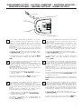
Konformitätserklärung
Der Unterzeichnende, in Vertretung des Herstellers:
Roger Technology – Via Botticelli 8, 31021 Bonisiolo di Mogliano V.to (TV)
ERKLÄRT, dass das nachfolgend beschriebene Gerät:
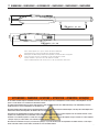
Beschreibung: Automatisierung für Drehtore
Modell: Serie SMARTY
mit den gesetzlichen Bestimmungen übereinstimmt, die folgende Richtlinien umsetzen:
• Richtlinie 2014/30/EU (EMV-Richtlinie) und darauf folgende Abänderungen
• Richtlinie 2014/35/EU (Niederspannungsrichtlinie) und darauf folgende Abänderungen
und dass alle im Folgenden aufgeführten Normen und/oder technischen Spezifikationen eingehalten wurden:
EN 61000-6-3
EN 61000-6-2
EN 60335-1
EN 60335-2-103
Die beiden letzten Ziffern des Jahres, in dem die | Kennzeichnung angebracht wurde 16.
Ort: Mogliano V.to Datum: 30/04/2016 Unterschrift
Alle Rechte bezüglich dieser Veröffentlichung sind ausschließliches Eigentum von ROGER TECHNOLOGY.
ROGER TECHNOLOGY behält sich das Recht vor, eventuelle Änderungen ohne Vorankündigung anzubringen. Kopien, Scannen, Überarbeitungen oder Änderungen sind ohne vorherige
schriftliche Zustimmung durch ROGER TECHNOLOGY ausdrücklich verboten.
Diese Bedienungsanleitung und die Gebrauchsanweisungen für den Installateur werden auf Papier geliefert und sind in der Produktverpackung enthalten.
Die digitale Fassung (PDF) und alle eventuellen zukünftigen Aktualisierungen stehen im geschützten Bereich unserer Website www.rogertechnology.com/B2B auf der Seite Self Service zur
Verfügung.
KUNDENDIENST ROGER TECHNOLOGY:
Aktiv: Montag bis Freitag Von 8:00 bis 12:00 Uhr und von 13:30 bis 17:30 Uhr
Telefon: +39 041 5937023
E-Mail: service@rogertechnology.it
Skype: service_rogertechnology
Seite wird geladen ...
Seite wird geladen ...
Seite wird geladen ...

8
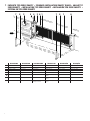
1 IMPIANTO TIPO SERIE SMARTY • STANDARD INSTALLATION SMARTY RANGE • ANLAGETYP
SERIE SMARTY • INSTALLATION TYPE SÉRIE SMARTY • INSTALACIÓN TIPO SERIE SMARTY •
SISTEMA DO TIPO SÉRIE SMARTY
DESCRIZIONE DESCRIPTION BESCHREIBUNG DESCRIPTION DESCRIPCIÓN DESCRIÇÃO
1
Automatismo SMARTY Automatism SMARTY Automatisierung SMARTY Automatisme SMARTY Automatismo SMARTY Automatismo SMARTY
2
Centrale di comando Control unit Steuerung Centrale de commande Central de mando Central de comando
3
Selettore a chiave Key selector Schlüsseltaster Sélecteur à clé Selector de llave Selector de chave
4
Lampeggiante Flashing light Blinkleuchte Clignotant Luz intermitente Lampejante
5
Antenna Antenna Antenne Antenne Antena Antena
6
Fotocellula esterna External photocell Externe Lichtschranke
Cellule photoélectrique
externe
Barrera fotoeléctrica exte-
rior
Sensor fotoelétrico externo
7
Fotocellula interna Internal photocell Interne Lichtschranke
Cellule photoélectrique
interne
Barrera fotoeléctrica interior Sensor fotoelétrico exterior
8
Fermo meccanico in apertura
Gate open mechanical stop
Mechanische Feststellvor-
richtung beim Öffnen
Butée mécanique en ou-
verture
Tope mecánico de apertura
Retentor mecânico em abertura
4x1-RX
2x1-TX
3x2.5
3x2.5
2x1-TX
4x1-RX
3x1.5/230 V
3x1
2x1.5
RG58
872 354 61 8617
230Vac
Seite wird geladen ...
Seite wird geladen ...

11
SMARTY5 SMARTY5R5 SMARTY7 SMARTY7R SMARTY4/HS
TIPOLOGIA D‘USO • USAGE TYPE • ART DER NUTZUNG
TYPE D‘UTILISATION • TIPO DE USO •TIPO DE USO
CONDOMINIALE • CONDOMINIUM • MITEIGENTÜMER
DE COPROPRIÉTÉ • DE LA COMUNIDAD • DE COPROPRIEDADE
TIPO MOTORE • MOTOR TYPE • ART DER MOTOR
TYPE DE MOTEUR • TIPO DE MOTOR • TIPO DE MOTOR
IRREVERSIBILE
IRREVERSIBLE
IRREVERSIBEL
IRRÉVERSIBLE
IRREVERSIBLE
IRREVERSÍVEL
REVERSIBILE
REVERSIBLE
REVERSIBEL
RÉVERSIBLE
REVERSIBLE
REVERSÍVEL
IRREVERSIBILE
IRREVERSIBLE
IRREVERSIBEL
IRRÉVERSIBLE
IRREVERSIBLE
IRREVERSÍVEL
REVERSIBILE
REVERSIBLE
REVERSIBEL
RÉVERSIBLE
REVERSIBLE
REVERSÍVEL
IRREVERSIBILE
IRREVERSIBLE
IRREVERSIBEL
IRRÉVERSIBLE
IRREVERSIBLE
IRREVERSÍVEL
ALIMENTAZIONE MOTORE BRUSHLESS • BRUSHLESS MOTOR POWER
SUPPLY • EINSPEISUNG BRUSHLESS MOTOR • ALIMENTATION MOTEUR
BRUSHLESS • ALIMENTACION MOTOR BRUSHLESS • ALIMENTAÇÃO MO-
TOR BRUSHLESS
V 36
POTENZA NONIMALE • RATED POWER • NENNLEISTUNG
PUISSANCE NOMINALE • POTENCIA NOMINAL • POTÊNCIA NOMINAL
W 200 200 200 200 200
INTERMITTENZA • JOGGING • AUSSETZENDER BETRIEB •
INTERMITTENCE • INTERMITENCIA • INTERMITÊNCIA
USO INTENSIVO • INTENSIVE USE • INTENSIVE NUTZUNG
UTILISATION INTENSIVE • USO INTENSIVO • USO INTENSIVO
TEMPERATURA DI ESERCIZIO • WORKING TEMPERATURE • BETRIEBSTEM-
PERATUR • TEMPERATURE DE SERVICE • TEMPERATURA DE FUNCIONA-
MIENTO • TEMPERATURA DE FUNCIONAMENTO
°C
-20°C +55°C
GRADO DI PROTEZIONE • PROTECTION RATING • SCHUTZGRAD • DEGRE
DE PROTECTION • GRADO DE PROTECCION • GRAU DE PROTECÇÃO
IP 44
PESO OPERATORE • OPERATOR WEIGHT • ANTRIEBSGEWICHT • POIDS
OPERATEUR • PESO DEL OPERADOR • PESO DO OPERADOR
kg 11,7 11,7 12,2 13,2 11,7
TEMPO APERTURA PER 90° • 90° OPENING TIME • ÖFFNUNGSZEIT FÜR 90°
• TEMPS OUVERTURE POUR 90° • TIEMPO PARA APERTURA DE 90° • TEMPO
DE ABERTURA PARA 90°
s 25 ÷ 40 20 ÷ 40 35 ÷ 50 15 ÷ 25
VELOCITÀ • WORKING SPEED • GESCHWINDIGKEIT DER TORBEWEGUNG
• VITESSE DE MANOEUVRE • VELOCIDAD DE MANIOBRA • VELOCIDADE
DE MANOBRA
cm/s 1,6 ÷ 1 1,8 ÷ 1,2 1,6 ÷ 1 1,6 ÷ 1 2 ÷ 1
SPINTA • TRUST • SCHUB • POUSSEE • EMPUJE • IMPULSO N 600 ÷ 7000 600 ÷ 6500 600 ÷ 7000 600 ÷ 6500 600 ÷ 4500
CORSA • TRAVEL • HUB • COURSE • CARRERA • CURSO mm max 370 max 520 max 370
CICLI DI MANOVRA GIORNO (APERTURA/CHIUSURA - 24 ORE NON STOP)
OPERATING CYCLES PER DAY (OPENING/CLOSING - 24 HOURS NO STOP)
BETRIEBSZYKLEN PRO TAG (ÖFFNEN/ SCHLIESSEN - 24 STUNDEN NON-STOP)
CYCLES DE FONCTIONNEMENT PAR JOUR (OUVERTURE / FERMETURE 24
HEURES SANS ARRÊT)
CICLOS DE MANIOBRA POR DÌA (APERTURA/CIERRE – 24 HORAS SIN PARAR)
CICLOS DE MANOBRA POR DÌAS (ABERTURA/ENCERRAMENTO - 24 HORAS NON-STOP)
n° 1000
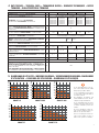
4 DATI TECNICI • TECHICAL DATA • TECHNISCHE DATEN • DONNEES TECHNIQUES • DATOS
TECNICOS • CARACTERÍSTICAS TÉCNICAS
5 DIAGRAMMA DI UTILIZZO • WORKING DIAGRAM • VERWENDUNGSDIAGRAMM •DIAGRAMME
D’UTILISATION • DIAGRAMA DE UTILIZACION • DIAGRAMA DE UTILIZAÇÃO
In caso di installazione in zone sog-
gette a forte raffiche di vento, i limiti
di impiegono potrebbero ridursi.
In case of installation in areas subject
to strong gusts of wind, the limits of
use may be reduced.
Bei Installation in Gebieten mit
starken Windböen können die Ein-
satzgrenzen eingeschränkt sein.
En cas d‘installation dans des zones
soumises à de fortes rafales de vent,
les limites d‘utilisation peuvent être
réduites.
En caso de instalación en áreas su-
jetas a fuertes ráfagas de viento, los
límites de uso pueden reducirse.
Em caso de instalação em áreas su-
jeitas a fortes rajadas de vento, os
limites de uso podem ser reduzidos.
300
200
100
0
kg
m
SMARTY 5
1
400
500
2 345
600
700
m
SMARTY 7R
600
400
200
0
kg
m1
800
1000
234567
1200
1400
300
200
100
0
kg
m
SMARTY 4HS
1
400
500
234
600
700
300
200
100
0
kg
m
SMARTY 5R5
1
400
500
2345
600
700
600
400
200
0
kg
SMARTY 7
1
800
1000
2 34567
1200
1400

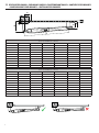
12
SMARTY 5 / SMARTY 5R5 / SMARTY 4HS
(Corsa massima/Max run = 370 mm)
A B C (max) D (max) E G
α°
150 150 120 1030 100 130 97°
150 170 120 1030 100 130 96°
150 190 120 1030 100 130 95°
150 200 120 1030 100 130 95°
150 220 120 1030 100 130 90°
170 150 120 1030 100 130 103°
170 170 120 1030 100 130 102°
170 200 120 1030 100 130 90°
185 185 120 1030 100 130 90°
200 160 120 1030 100 130 92°
SMARTY 7 / SMARTY 7R
(Corsa massima/Max run = 520 mm)
A B C (max) D (max) E G
α°
200 200 200 1180 140 170 98°
200 230 200 1180 140 170 97°
200 260 200 1180 140 170 96°
200 280 200 1180 140 170 95°
200 300 200 1180 140 170 93°
220 220 200 1180 140 170 102°
220 250 200 1180 140 170 100°
220 280 200 1180 140 170 93°
250 200 200 1180 140 170 106°
250 250 200 1180 140 170 94°
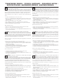
6 VERIFICHE PRELIMINARI • PRELIMINARY CHECKS • EINLEITENDE KONTROLLEN • CONTRÔLES PRÉLIMINAIRES
• COMPROBACIONES PRELIMINARES • CONTROLOS PRELIMINARES
D
B
A
E
G
C
60

13
IT
VERIFICHE PRELIMINARI PRIMA DELL’INSTALLAZIONE
• Verificare che la struttura del cancello sia robusta.
• Verificare che i cardini siano ben ingrassati e che il movimento sia fluido e
regolare per tutta la sua corsa e senza attriti.
• Prevedere sempre una battuta meccanica di arresto in apertura e chiusura ben
fissata al suolo, dotata di un elemento elastico (esempio: gomma) che attutisca
l’arrivo in battuta dell’anta.
In funzione al modello da installare, agli spazi e agli ingombri presenti in sito e
in funzione all‘angolo di apertura desiderato, posizionare la staffa posteriore sul
pilastro e verificare le misure di installazione indicate in tabella.
Le misure [A] e [B] devono essere sempre compatibili con la corsa utile del pis-
tone.
Se la somma di [A]+[B] è maggiore della corsa massima, si deve accorciare la
staffa posteriore, riducendo di conseguenza la misura [B]
NOTA: per avere un movimento regolare del cancello, le misure [A] e [B] devono
essere sempre maggiori della misura [G] di almeno 20-30 mm.
La misura [G] indicata in tabella è stata calcolata ipotizzando un‘anta di spessore
60 mm.
• La punta del pistone deve convergere verso l‘anta.
• Aprendo manualmente l‘anta verificare che il pistone non vada in col-
lisione con l‘anta o il pilastro.
EN
PRELIMINARY CHECKS
• Check that the structure of the gate is sturdy and in good condition.
• Check that the hinges are well greased and that the gate moves throughout its
entire travel smoothly without impediment or friction.
• Always install mechanical stops in the gate open and gate closed positions,
anchored securely to the ground and with elastic damper elements (e.g. rubber
buffer) to attenuate the impact of the gate leaf against the stop.
Depending on the model installed, on the available space and any obstacles exis-
ting in the installation site, and on the required angle of aperture, install the rear
bracket on the pillar and the check that the installation measurements indicated
in the table are correct.
The measurements [A] and [B] must always be compatible with the maximum
effective travel of the piston.
If the sum of the values [A]+[B] is greater than the maximum travel, shorten the
rear bracket to reduce measurement [B]
N.B: for the gate to operate smoothly and correctly, the measurements [A] and
[B] must always be approximately 20-30 mm greater than measurement [G].
The measurement [G] indicated in the table was calculated considering a gate
leaf thickness of 60 mm.
• The end of the piston rod must meet the gate leaf.
• When opening the wing manually, check that the piston does not col-
lide with the wing or the pillar.
DE
EINLEITENDE KONTROLLEN
• Sicherstellen, dass die Struktur des Tors robust ist.
• Sicherstellen, dass die Angeln gut eingefettet sind und die Bewegung über den
gesamten Torlauf flüssig und regelmäßig, ohne Reibungen erfolgt.
• Stets einen mechanischen Anschlag in Öffnung und Schließung vorsehen, der
fest am Boden verankert ist und über ein elastisches Element (z.B.: Gummi)
verfügt, das den Anschlag des Torflügels dämpft.
Je nach zu installierendem Modell, Raum und Platzbedarf vor Ort sowie ge-
wünschtem Öffnungswinkel, den hinteren Bügel auf dem Pfeiler positionieren
und die in der Tabelle angegebenen Installationsmaße überprüfen.
Die Maße [A] und [B] müssen immer mit dem Arbeitshub des Kolbens kompatibel
sein.
Wenn die Summe von [A]+[B] größer ist als der Maximalhub, muss man den
hinteren Bügel verkürzen und demzufolge das Maß [B] reduzieren
HINWEIS: Damit das Tor sich regelmäßig bewegt, müssen die Maße [A] und [B]
immer um mindestens 20-30 mm größer sein als das Maß [G].
Das in der Tabelle angegebene Maß [G] wurde unter Annahme eines Torflügels
von 60 mm Dicke berechnet.
• Die Spitze des Kolbens muss zum Flügel gerichtet sein.
• Den Flügel von Hand öffnen und sicherstellen, dass der Kolben nicht
mit dem Flügel oder dem Pfeiler zusammenstößt
CONTRÔLES PRÉLIMINAIRES
FR
• Vérifier que la structure du portail soit robuste.
• Vérifier que les gonds soient bien graissés et que le mouvement soit fluide et
régulier sur toute la course et sans frottements.
• Toujours prévoir une butée mécanique d‘arrêt en ouverture et fermeture bien
fixée au sol, dotée d‘un élément élastique (exemple : caoutchouc) qui amortis-
se l‘arrivée en butée du vantail.
En fonction du modèle à installer, des espaces et des encombrements présents
sur place et en fonction de l‘angle d‘ouverture souhaité, placer l‘étrier arrière sur
le pilier et vérifier les cotes d‘installation indiquées dans le tableau.
Les cotes [A] et [B] doivent toujours être compatibles avec la course utile du
piston.
Si la somme [A]+[B] est supérieure à la course maximale, raccourcir l‘étrier arri-
ère, en réduisant de conséquence la cote [B]
REMARQUE : pour obtenir un mouvement régulier du portail, les cotes [A] et [B]
doivent toujours être supérieures à la cote [G] d‘au moins 20-30 mm.
La cote [G] indiquée dans le tableau a été calculée en supposant un vantail d‘une
épaisseur de 60 mm.
• La pointe du piston doit converger vers le vantail.
• En ouvrant manuellement le vantail vérifier si le piston heurte ce der-
nier ou le pilier.
ES
COMPROBACIONES PRELIMINARES
• Compruebe que la estructura de la cancela sea sólida.
• Compruebe que los goznes estén bien engrasados y que el movimiento sea
fluido y regular en toda su carrera y no presente roces.
• Monte siempre un tope mecánico para la apertura y el cierre bien fijada al
suelo,dotada de un elemento elástico (ejemplo: goma) que amortigüe la llega-
da de la hoja al cerrarse.
En función del modelo que se ha de instalar, del espacio y las dimensiones que
se encuentran in situ y en función del ángulo de apertura deseado, coloque el
estribo trasero sobre el pilar y consulte las medidas de instalación que figuran
en la tabla.
Las medidas [A] y [B] siempre han de ser compatibles con la carrera útil del
pistón.
Si la suma de [A]+[B] es superior a la carrera máxima, se deberá acortar el
estribo trasero, reduciendo por tanto la medida [B]
NOTA: para que el movimiento de la cancela sea constante, las medidas [A] y [B]
siempre han de ser superiores a la medida [G] al menos 20-30 mm.
La medida [G] que se indica en la tabla se ha calculado tomando como referencia
una hoja de 60 mm de espesor.
• La punta del pistón ha de converger hacia la hoja.
• Abriendo manualmente la hoja, controle que el pistón no choque con
la hoja o el pilar.
PT
CONTROLOS PRELIMINARES
• Verifique se a estrutura do portão é resistente.
• Verifique se as dobradiças estão adequadamente lubrificadas e se o movimen-
to é fluido e regular durante todo o seu curso sem atritos.
• Sempre preveja um batente mecânico de paragem em abertura e fecho bem
fixo ao solo, fornecido de um elemento elástico (por exemplo: borracha) que
amorteça a chegada em batida da portinhola.
Em função ao modelo a ser instalado, aos espaços e às dimensões presentes
no local e, dependendo do ângulo de abertura desejado, coloque o suporte
traseiro no pilar e verifique as medidas de instalação indicadas na tabela.
As medidas [A] e [B] deverão sempre ser compatíveis com o curso útil do
pistão.
Se a soma de [A] + [B] for maior do que o curso máximo, é necessário encurtar
o suporte posterior, reduzindo assim a medida [B]
NOTA: para ter um movimento regular do portão, as medidas [A] e [B] tem de
ser sempre maiores do que a medida [G] de pelo menos 20-30 mm.
A medida [G] apresentada na tabela foi calculada considerando uma espessura
da portinhola de 60 mm.
• A ponta do pistão tem que convergir com o sentido da folha.
• Ao abrir a porta manualmente, verifique se o pistão não colide com a
folha ou com o pilar.

14
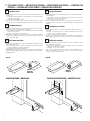
IT
FISSAGGIO STAFFE
1. Fissare la staffa posteriore in bolla come da misure di installazione indicate al
paragrafo 6.
• Su pilastri in muratura utilizzare le staffe predisposte per il tipo di materiale
con tasselli e viti adeguate.
• Su pilastri in ferro saldare la staffa.
2. Con cancello completamente chiuso posizionare la staffa anteriore, rispettando
le misure [D] e [E] e fissarla in bolla all’anta del cancello, come indicato in figura.
EN
FASTENING BRACKETS
1. Fasten the rear bracket in a perfectly level position and in accordance with the
installation measurements indicated in paragraph 6.
• For masonry/cement pillars, use the specific masonry brackets with suitable
anchor bolts and screws.
• With steel pillars, weld the bracket in place.
2. With the gate completely closed, fit the front bracket to obtain the installation
measurements [D] and [E], and fasten in a perfectly level position to the gate
leaf as shown in the figure.
DE
BEFESTIGUNG DER BÜGEL
1. Den hinteren Bügel nivelliert nach den im Abschnitt 6 angegebenen Instal-
lationsmaßen befestigen.
• Bei gemauerten Pfeilern die für dieses Material vorgesehenen Bügel mit
geeigneten Dübeln und Schrauben verwenden.
• Bei Eisenpfeilern den Bügel anschweißen.
2. Bei vollständig geschlossenem Tor den vorderen Bügel unter Einhaltung der
Maße [D] und [E] anbringen und nivelliert am Torflügel befestigen, wie in der
Abbildung gezeigt.
60
60
150
100
70
120
Ø12
10
PILASTRI IN FERRO - IRON PILLAR PILASTRI IN CALCESTRUZZO - CONCRETE PILLAR
FR
FIXATION DES ÉTRIERS
1. Fixer l’étrier arrière à niveau conformément aux cotes d’installation indiquées
au paragraphe 6.
• Sur les piliers en maçonnerie, utiliser les étriers prédisposés pour le type de
matériau avec chevilles et vis appropriées.
• Sur les piliers en fer, souder l’étrier.
2. Avec le portail entièrement fermé, placer l’étrier avant, en respectant les cotes
[D] et [E] et la fixer à niveau avec le vantail du portail, comme indiqué dans
la figure.
ES
FIJACIÓN DE LOS ESTRIBOS
1. Fije el estribo trasero a plomo según las medidas de instalación indicadas en el
apartado 6.
• En pilares de hormigón utilice los estribos preinstalados para el tipo de
material con tacos y tornillos adecuados.
• Suelde el estribo en los pilares de hierro.
2. Con la cancela cerrada del todo coloque el estribo delantero, respetando las me-
didas [D] y [E] y fíjelo a plomo a la hoja de la cancela como se indica en la figura.
PT
FIXAÇÃO DOS SUPORTES
1. Fixe o suporte traseiro com um nível de bolha conforme as medidas de insta-
lação indicadas no parágrafo 6.
• Em pilares de alvenaria use os suportes adequados para o tipo de material
com buchas e parafusos apropriados.
• Em pilares de ferro solde o suporte.
2. Com o portão completamente fechado posicione o suporte dianteiro, respei-
tando as medidas [D] e [E] e fixe-o com um nível de bolha à portinhola do
portão, conforme mostrado na figura.
7 FISSAGGIO STAFFE • BRACKETS FASTENING • BEFESTIGUNG DER BÜGEL • FIXATION DES
ÉTRIERS • FIJACIÓN DE LOS ESTRIBOS • FIXAÇÃO DOS SUPORTES
230
80
200
140
170
80
SMARTY7
SMARTY7R
100
130
80
SMARTY5
SMARTY5R5
SMARTY4/HS
KT237
230
80
200
KT238

15
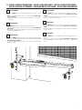
IT
INSTALLAZIONE
• Il pistone SMARTY può essere installato indifferentemente a destra o a sin-
istra.
• Fissare il pistone alla staffa posteriore e a quella anteriore lubrificando i
punti di rotazione.
• Muovendo manualmente il cancello verificare che tutta la corsa sia regolare
e senza attriti.
EN
INSTALLATION
• The SMARTY piston may be installed on the right or left hand side.
• Fasten the piston to the rear bracket and to the front bracket, lubricating the
pivot points.
• Move the gate manually and check that it moves smoothly throughout its entire
travel without impediment or friction.
DE
INSTALLATION
• Der Kolben SMARTY kann unterschiedslos rechts oder links installiert werden.
• Den Kolben am hinteren Bügel und am vorderen Bügel befestigen, dabei die
Rotationspunkte schmieren.
• Das Tor von Hand bewegen und prüfen, dass sein Lauf regelmäßig und
reibungslos erfolgt.
FR
INSTALLATION
• Le piston SMARTY peut être installé indifféremment à droite ou à gauche.
• Fixer le piston à l’étrier arrière et l’étrier avant en lubrifiant les points de
rotation.
• Tout en actionnant manuellement le portail, vérifier que toute la course soit
régulière et dépourvue de frottements.
ES
INSTALACIÓN
• El pistón SMARTY puede instalarse tanto a la derecha como a la izquierda.
• Fije el pistón al estribo trasero y al delantero lubricando los puntos de ro-
tación.
• Moviendo a mano la cancela, compruebe que toda la carrera sea homogénea
y no presente roces.
PT
INSTALAÇÃO
• O pistão SMARTY pode ser instalado quer no lado direito quer no lado es-
querdo.
• Fixe o pistão ao suporte traseiro e ao dianteiro lubrificando as articulações.
• Movendo manualmente o portão verifique se todo o curso é regular e sem
atritos.
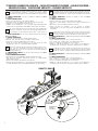
8 INSTALLAZIONE AUTOMAZIONE • INSTALLATION DRIVE UNIT • INSTALLATION DES ANTRIEBS •
INSTALLATION DE ACTIONNEUR • INSTALACIÓN DEL ACTUADOR • INSTALAÇÃO ACCIONADOR

16
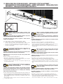
IT
Utilizzare i fermi meccanici interni al pistone come
ulteriore sicurezza di arresto alle battute meccaniche del
cancello.
ATTENZIONE: i fermi meccanici sono allentati all’interno del pistone.
ANCHE SE NON UTILIZZATI VANNO SEMPRE FISSATI.
Le battute meccaniche del cancello in apertura e chiusura devono
sempre essere predisposte.
Per regolare i fermi meccanici è possibile agire dal basso, oppure:
• Togliere il tappo [A] e sfilare la copertura della vite di traino [B].
• Portare il cancello in posizione di massima apertura e regolare il fermo
meccanico in apertura [C], stringendo le viti come indicato in figura 2.
• Eseguire la stessa operazione anche in chiusura e regolare il fermo
meccanico in chiusura [D]
EN
Use the internal mechanical stops in the piston as a
supplementary safety measure in addition to the
mechanical stops of the gate.
WARNING: the mechanical stops have become loose inside the piston.
Even if not used, they must always be securely fastened.
Mechanical stops in the gate open and gate closed positions must
always be used.
Adjust the mechanical stops from underneath, or:
• Remove the cap [A] and remove the drive screw cover [B].
• Move the gate into the fully open position and adjust the gate open mechanical
stop [C], tightening the screws as shown in fig. 2.
• Perform the same procedure in the gate closed position to adjust the gate
closed mechanical stop [D].
DE
Die mechanischen Feststeller im Inneren des Kolbens als
weiteren Sicherheitsstopp an den mechanischen
Anschlägen des Tors verwenden.
ACHTUNG: Die mechanischen Feststeller sind im Kolben locker.Auch
wenn sie nicht verwendet werden, müssen sie immer befestigt werden.
Die mechanischen Anschläge des Tors in Öffnung und Schließung
müssen immer angebracht werden.
Um die mechanischen Feststeller einzustellen, kann man von unten vorgehen oder:
• Den Deckel [A] abnehmen und die Abdeckung [B] der Zugschraube abziehen.
• Das Tor in maximal geöffnete Position bringen und den mechanischen Fest-
steller in Öffnung [C] einstellen, indem man die Schrauben festzieht, wie in
Abb. 2 gezeigt.
• Beim Schließen ebenso vorgehen und den mechanischen Feststeller in
Schließung [D] einstellen.
A
B
C
D
Stringere con forza
Tighten strongly
Stringere con forza
Tighten strongly
Fig. 1
1
42
3
Fig. 2
FR
Utiliser les fermoirs mécaniques intérieurs au piston
comme sécurité d’arrêt supplémentaire aux butées méca-
niques du portail.
ATTENTION : les butées mécaniques sont desserrées à l’intérieur du
piston. Même si elles ne sont pas utilisées, elles doivent toujours être
fixées.
Les butées mécaniques du portail en ouverture et en fermeture doivent
toujours être prédisposées.
Pour régler les fermoirs mécaniques, il est possible d’agir du bas, ou :
• Retirer le bouchon [A] et défiler le couvercle [B] de la vis de traction.
• Porter le portail en position d’ouverture maximale et régler le fermoir mécan-
ique en ouverture [C], en serrant les vis comme indiqué en fig. 2.
• Effectuer la même opération en fermeture et régler le fermoir mécanique en
fermeture [D].
ES
Utilice los retenes mecánicos situados dentro del pistón
como elemento de seguridad adicional de los topes
mecánicos de la cancela.
ATENCIÓN: Los topes mecánicos están flojos dentro del pistón. Aunque
no se utilicen siempre tienen que fijarse.
Siempre han de estar preinstalados los topes mecánicos de la cancela
al abrirse y al cerrarse.
Para ajustar los retenes mecánicos puede actuarse desde abajo, o:
• Quite el tapón [A] y extraiga la cobertura [B] del tornillo de arrastre.
• Coloque la cancela en la posición de apertura máxima y ajuste el retén
mecánico de la apertura [C], apretando los tornillos como se indica en la fig. 2.
• Efectúe la misma operación para el cierre y ajuste el retén mecánico del cierre
[D].
PT
Use os retentores mecânicos no interior do pistão como
sistema de segurança adicional para parar os batentes
mecânicos do portão.
ATENÇÃO: os batentes mecânicos estão frouxos no interior do pistão.
Mesmo quando não são utilizados, devem sempre ser fixados.
Os batentes mecânicos do portão em abertura e em fecho devem
sempre ser predispostos.
Para ajustar os retentores mecânicos é possível atuar a partir de baixo, ou:
• Retire o tampão [A] e desenfie a cobertura [B] do parafuso de acionamento.
• Leve o portão em posição de máxima abertura e ajuste o retentor mecânico na
abertura [C], apertando os parafusos conforme mostrado na fig. 2.
• Faça o mesmo também no fecho e ajuste o retentor mecânico no fecho [D].
9 REGOLAZIONE DEL FERMO MECCANICO • MECHANICAL STOPS ADJUSTMENT •
MECHANISCHE FESTSTELLVORRICHTUNGEN • ARRÊTS MÉCANIQUES • REGULACIÓN TOPES
MECÁNICOS • REGULAÇÃO SEGURANÇAS MECÂNICAS

17
Z
Y
X
3 x 2.5 mm²
Z
Y
X
10 COLLEGAMENTI ELETTRICI • ELECTRICAL CONNECTIONS • ELEKTRISCHE ANSCHLÜSSE •
CONNEXIONS ÉLECTRIQUES • CONEXIONES ELÉCTRICAS • LIGAÇÕES ELÉCTRICAS
Prevedere sulla rete di alimentazione un interruttore o un sezionatore
onnipolare con distanza di apertura dei contatti uguale o superiore a 3
mm.
Verificare che a monte dell’impianto elettrico vi sia un interruttore
differenziale con soglia di 0,03 A ed una protezione di sovracorrente
adeguati nell’osservanza della Buona Tecnica ed in ottemperanza alle
norme vigenti.
Quando richiesto, collegare l’automazione ad un efficace impianto di
messa a terra eseguito come indicato dalle vigenti norme di sicurezza.
1. Collegare il cavo di alimentazione 3x2,5 mm
2
alla centrale di comando.
2. NON È NECESSARIO per la messa in funzione dello SMARTY, eseguire
il collegamento di messa a terra.
I collegamenti degli accessori e il collaudo dei motoriduttori SMARTY
sono illustrati nel manuale di installazione della centrale di comando
EDGE1.
Am Versorgungsnetz einen allpoligen Schalter oder Trennschalter mit
Öffnungsabstand der Kontakte von mindestens 3 mm einbauen.
Prüfen, ob sich vor der Elektroanlage ein geeigneter
Fehlerstromschutzschalter mit Schwellenwert 0,03 A und Überstromschutz
befinden, unter Beachtung der technischen Regeln und der geltenden
Normen.
Falls vorgeschrieben, den Antrieb an eine wirksame und den
Sicherheitsnormen entsprechende Erdungsanlage anschließen.
1. Schließen Sie das 3 x 2,5 mm
2
-Stromkabel an die Steuerung an.
2. Für die Inbetriebnahme von SMARTY ist es NICHT NOTWENDIG den
Erdungsanschluss durchzuführen.
Die Anschlüsse des Zubehörs und die Abnahmeprüfung der
Getriebemotoren SMARTY werden im Installationshandbuch des
Steuergeräts EDGE1 dargestellt.
A switch or an omnipolar cut-off switch with a contact opening of at least
3 mm must be installed on the mains power line.
Ensure that an adequate residual current circuit breaker with a threshold
of 0.03 A and a suitable over-current cut-out are installed ahead of the
electrical installation in accordance with best practices and in compliance
with applicable legislation.
When requested, connect the automation to an effective earthing system
that complies with current safety standards.
1. Connect the 3x2.5 mm
2
power cable to the control unit.
2. To start the SMARTY device, it IS NOT NECESSARY to perform the
earthing connection.
The accessory connections and the SMARTY gear motor tests are
illustrated in the installation manual of the EDGE1 control unit.
Prévoir sur le réseau d’alimentation un interrupteur ou un dispositif de
coupure omnipolaire avec distance d’ouverture des contacts égale ou
supérieure à 3 mm.
Vérifier qu’un disjoncteur différentiel avec un seuil de 0,03 A et une
protection contre la surintensité adéquats sont installés en amont
de l’installation électrique, selon les règles de la bonne technique et
conformément aux normes en vigueur.
Si nécessaire, raccorder l’automatisme à une installation efficace de mise
à la terre, exécutée conformément aux normes de sécurité en vigueur.
1. Connectez le câble d’alimentation 3x2,5 mm
2
à l’unité de contrôle.
2. Il N’EST PAS NÉCESSAIRE, pour la mise en marche du SMARTY, de
brancher l’installation de mise à la terre.
Les branchements des accessoires et l’essai des motoréducteurs
SMARTY sont illustrés dans le manuel d’installation de la centrale de
commande EDGE1.
EN
FRIT
DE
Monte un interruptor/seccionador omnipolar con distancia de apertura de
los contactos igual o superior a 3 mm en la red de alimentación eléctrica.
Compruebe que antes de la instalación eléctrica haya un interruptor
diferencial con umbral de 0,03 A y una protección de sobrecorriente
adecuados, en conformidad con las prácticas de la buena técnica y las
normativas vigentes.
Cuando sea necesario, conecte el automatismo a una instalación de
puesta a tierra eficaz realizada según la normativa vigente en materia
de seguridad.
1. Conecte el cable de alimentación de 3x2.5 mm
2
a la unidad de control.
2. Para poner en funcionamiento SMARTY, NO ES NECESARIO realizar la
conexión de puesta a tierra.
Las conexiones de los accesorios y la prueba de los motorreductores
SMARTY se ilustran en el manual de instalación de la central de mando
EDGE1.
Prepare na rede de alimentação um interruptor ou um seccionador uni-
polar com distância de abertura dos contatos igual, ou superior a 3 mm.
Verifique se, a montante da instalação elétrica, há um interruptor diferen-
cial com limiar de 0,03 A e uma proteção de sobrecarga de acordo com
os critérios da Boa Técnica e em conformidade com as normas em vigor.
Quando exigido, ligue a automação a um sistema de ligação à terra efi-
ciente realizado em conformidade com as normas de segurança em vigor.
1. Conecte o cabo de força de 3x2,5 mm
2
à unidade de controle.
2. NÃO É NECESSÀRIO para a colocação em funcionamento do SMARTY,
realizar a ligação à terra.
As conexões dos acessórios e teste dos motorredutores SMARTY são
ilustrados no manual de instalação da central de comando EDGE1.
ES
PT

18
IT
L’encoder permette di calcolare l’esatta posizione del cancello e quindi,
dopo una interruzione di tensione o lo sblocco del cancello, al primo
comando ricevuto la centrale recupera immediatamente la posizione delle
ante.
Per SMARTY REVERSIBILE: l’encoder è installato di fabbrica da ROGER
TECHNOLOGY.
Per SMARTY IRREVERSIBILE:
• Fissare l’encoder sul motore come indicato in figura.
• Far passare il cavo come indicato e bloccarlo con l’apposito fermacavi.
• Collegare l’encoder in parallelo alle fasi del motore.
• Abilitare l’encoder al parametro 71 01 ed eseguire la procedura di apprendi-
mento della corsa (vedi manuale di installazione della centrale di comando).
EN
The encoder determines the precise position of the gate, and allows the
controller to reacquire the position of the gate leaf immediately when the
first command is received following a power failure or after the gate is
unlocked.
For SMARTY REVERSIBLE: the encoder is already installed in the factory by
ROGER TECHNOLOGY.
For SMARTY IRREVERSIBLE:
• Fasten the encoder to the motor as indicated in the figure.
• Route the cable as shown and secure it with the cable retainer.
• Connect the encoder in parallel with the motor phases.
• Enable the encoder with the parameter 71 01 and perform the travel
acquisition procedure (see control unit installation manual).
DE
Der Encoder ermöglicht die Berechnung der genauen Position des Tors,
daher stellt das Steuergerät nach einem Stromausfall oder der
Entriegelung des Tors beim ersten erhaltenen Befehl unverzüglich die
Position der Flügel wieder her.
Bei UMKEHRBAREM SMARTY: Der Encoder wird werkseitig von ROGER
TECHNOLOGY installiert.
Bei NICHT UMKEHRBAREM SMARTY:
• Den Encoder wie aus der Abbildung ersichtlich am Motor befestigen.
• Das Kabel wie angegeben durchziehen und mit der entsprechenden
Kabelschelle arretieren.
• Den Encoder parallel an die Motorphasen anschließen.
• Den Encoder über den Parameter 71 01 aktivieren und das Einlernverfahren
des Hubs durchführen (siehe das Installationshandbuch des Steuergeräts).
FR
L’encodeur permet de calculer la position exacte du portail et ainsi, après
une interruption de tension ou le déblocage du portail, dès la réception de
la première commande, la centrale récupère immédiatement la position
des vantaux.
Pour SMARTY RÉVERSIBLE: l’encodeur est installé en usine par ROGER
TECHNOLOGY.
Pour SMARTY IRRÉVERSIBLE :
• Fixer l’encodeur sur le moteur comme indiqué dans la figure.
• Faire passer le câble indiqué et le bloquer avec l’attache-câble prévu à cet
effet.
• Brancher l’encodeur en parallèle aux phases du moteur.
• Activer l’encodeur au paramètre 71 01 et exécuter la procédure
d’apprentissage de la course (voir manuel d’installation de la centrale de
commande).
ES
El codificador le permite calcular la posición exacta de la cancela y por tanto,
después de un corte de luz o del desbloqueo de la puerta, al primer comando
que recibe la centralita recupera de inmediato la posición de las hojas.
Para SMARTY REVERSIBLE: el codificador llega instalado de fábrica por ROGER
TECHNOLOGY.
Para SMARTY IRREVERSIBLE:
• Fije el codificador en el motor como se muestra en la figura.
• Pase el cable como se indica y fíjelo con la abrazadera de cables.
• Conecte el codificador en paralelo a las fases del motor.
• Habilite el codificador al parámetro 71 01 y realice el procedimiento de
aprendizaje de la carrera (véase el manual de instalación de la centralita).
PT
El codificador le permite calcular la posición exacta de la cancela y por
tanto, después de un corte de luz o del desbloqueo de la puerta, al primer
comando que recibe la centralita recupera de inmediato la posición de las
hojas.
Para SMARTY REVERSIBLE: el codificador llega instalado de fábrica por ROGER
TECHNOLOGY.
Para SMARTY IRREVERSIBLE:
• Fije el codificador en el motor como se muestra en la figura.
• Pase el cable como se indica y fíjelo con la abrazadera de cables.
• Conecte el codificador en paralelo a las fases del motor.
• Habilite el codificador al parámetro 71 01 y realice el procedimiento de
aprendizaje de la carrera (véase el manual de instalación de la centralita).
Marrone/Brown
MOTORE
MOTOR
SMARTY/EMA
Blu/Blue
Nero/Black
Marrone/Brown
MOTORE
MOTOR
Blu/Blue
Nero/Black
11 ENCODER MAGNETICO ASSOLUTO • ABSOLUTE MAGNETIC ENCODER • ABSOLUT ENCODER •
ENCODEUR ABSOLU • CODIFICADOR ABSOLUTO • ENCODER ABSOLUTO

19
12 MANUTENZIONE PERIODICA • PERIODICAL MAINTENANCE • REGELMÄSSIGE WARTUNG •
ENTRETIEN PÉRIODIQUE • MANTENIMIENTO PERIÓDICO • MANUTENÇÃO PERIÓDICA
NOTA: Per l’eventuale riparazione o sostituzione dei prodotto dovranno essere uti-
lizzati esclusivamente ricambi originali.
L’installatore deve fornire tutte le informazioni relative al funzionamento automati-
co, manuale e di emergenza della porta o cancello motorizzato, e consegnare all’utilizzatore
dell’impianto le istruzioni d’uso. L’installatore deve redigere il registro di manutenzione, nel
quale dovrà indicare tutti gli interventi di manutenzione ordinaria e straordinaria effettuati.
Effettuare degli interventi periodici di manutenzione. Consigliamo almeno ogni 6 mesi.
Togliere alimentazione di rete e batterie (se collegate) per evitare possibili situazioni di
pericolo.
• Scollegare l’alimentazione di rete e sbloccare il cancello.
• Verificare lo stato di deterioramento di tutti i materiali. In particolare verificare lo stato
di erosione o di ossidazione delle parti strutturali. Sostituire le parti che non forniscono
sufficienti garanzie.
• Verificare le viti di fissaggio e il loro corretto serraggio.
• Pulire e lubrificare i perni di rotazione, i cardini del cancello e la vite di traino.
• Verificare manualmente che lo scorrimento del cancello sia regolare e privo di attriti.
• Verificare il funzionamento dello sblocco manuale.
Ridare alimentazione di rete.
• Verificare il corretto intervento delle sicurezze e di tutte le funzioni di comando.
• Verificare il corretto funzionamento del rilevamento ostacoli.
• Verificare che le situazioni pericolose siano salvaguardate dalla limitazione delle forze ai
sensi della normativa EN 12445.
REMARQUE : Pour l’éventuelle réparation ou remplacement des produits, seules
des pièces de rechange originales devront être utilisées.
L’installateur doit fournir les informations relatives au fonctionnement automati-
que, manuel et d’urgence de la porte ou du portail motorisé, et remettre à l’utilisateur de
l’installation les consignes d’utilisation. L’installateur doit rédiger le registre d’entretien,
dans lequel il devra indiquer toutes les interventions d’entretien ordinaire et extraordinaire
effectuées. Effectuer des interventions périodiques d’entretien. Nous conseillons au moins
tous les 6 mois.
Couper l’alimentation de réseau et des batteries (si branchées) pour éviter les possibles
situations de danger.
• Débrancher la tension secteur et déverrouiller le portail.
• Vérifier l’état de détérioration de tous les matériaux. En particulier, vérifier l’état d’éro-
sion ou d’oxydation des pièces structurelles. Remplacer les pièces qui ne semblent pas
suffisamment fonctionnelles.
• Vérifier les vis de fixation et leur bon serrage.
• Nettoyer et lubrifier les axes de rotation, les charnières du portail et la vis d’entraînement.
• Vérifier manuellement si le glissement du portail est régulier et sans frottement.
• Vérifier le fonctionnement du déverrouillage manuel.
Remettre l’alimentation de réseau.
• Vérifier le bon fonctionnement des sécurités et de toutes les fonctions de commande.
• Vérifier le bon fonctionnement de la détection d’obstacles.
• Vérifier que les situations dangereuses soient empêchées par la limitation des forces
conformément à la norme EN 12445.
NOTE: Only use original spare parts when repairing or replacing products.
The installer must provide the user with complete instructions for using the moto-
rised door or gate in automatic, manual and emergency modes, and must deliver
the operating instructions to the user of the installation upon completion. The installer must
compile the maintenance log book, in which all scheduled and unscheduled maintenance
operations performed must be indicated. The installation must be subject to regular main-
tenance. We recommend servicing at least once every 6 months.
Disconnect from mains electricity and from battery power (if applicable) to avoid the risk
of accident or injury.
• Disconnect the system from mains electricity and unlock the gate.
• Check all parts for wear and deterioration. In particular, check all structural parts for
wear and corrosion. Replace any parts that are not in an adequate condition to ensure
continued correct operation.
• Check the condition and tightness of all fastener screws.
• Clean and lubricate the pivot pins, the gate hinges and the coupling screw.
• Manually check that the gate slides smoothly and without impediment.
• Check that the manual lock release system works.
Reconnect the mains power.
• Check that the safety devices and all the control functions work correctly.
• Check that the obstacle detection function works correctly.
• Check that the force limiting function prevents potentially dangerous situations in com-
pliance with the standard EN 12445.
NOTA: Utilice solo recambios originales para la reparación o la sustitución del
producto. El instalador debe facilitar toda la información relacionada con el funcio-
namiento automático, manual y de emergencia de la puerta o cancela motorizada,
y entregar al usuario de la instalación las instrucciones de uso. El instalador deberá redac-
tar el registro de mantenimiento, donde indicar todas las operaciones de mantenimiento
ordinario y extraordinario que lleva a cabo.
Realice tareas de mantenimiento periódico. Se recomienda por lo menos cada seis meses.
Desconecte la alimentación eléctrica y la batería (si está conectada) para evitar posibles peligros.
• Desconecte la alimentación eléctrica de la red y desbloquee la cancela.
• Compruebe el estado de deterioro de todos los materiales. Especialmente, compruebe
el estado de erosión o de oxidación de las partes estructurales. Sustituya las piezas que
no ofrezcan suficiente garantía.
• Compruebe los tornillos de fijación y que estén apretados correctamente.
• Limpie y lubrique los pernos de rotación, los goznes de la cancela y el tornillo de arrastre.
• Compruebe manualmente que el desplazamiento de la cancela sea regular y sin roces.
• Compruebe el funcionamiento del desbloqueo manual.
Vuelva a conectar la fuente de alimentación.
• Compruebe que los dispositivos de seguridad y todas las funciones de mando funcionen
correctamente.
• Compruebe que la detección de obstáculos funcione correctamente.
• Cerciórese de que se ha evitado cualquier situación peligrosa gracias a la limitación de
las fuerzas con arreglo a la norma EN 12445.
HINWEIS: Bei Reparaturen oder Austausch des Produktes dürfen ausschließlich
Originalersatzteile verwendet werden.
Der Installateur muss alle Informationen zum automatischen, manuellen und Not-
Betrieb des Tors liefern und dem Benutzer der Anlage die Gebrauchsanleitung übergeben.
Der Installateur muss das Register der Wartungsarbeiten erstellen, in dem alle durchgeführ-
ten Eingriffe der ordentlichen und außerordentlichen Wartung zu vermerken sind.
Regelmäßige Wartungsarbeiten durchführen. Wir empfehlen mindestens alle 6 Monate.
Stromversorgung von Netz und Akkus (falls angeschlossen) trennen, um mögliche Gefah-
rensituationen zu vermeiden.
• Die Stromversorgung unterbrechen und das Tor entriegeln.
• Den Zustand aller Materialien überprüfen. Insbesondere die Erosion oder Oxidation der
strukturellen Teile prüfen. Die Teile, die nicht ausreichend sicher erscheinen, austau-
schen.
• Die Befestigungsschrauben und ihren korrekten Anzug prüfen.
• Die Drehstifte, die Torangeln und die Zugschraube reinigen und schmieren.
• Von Hand prüfen, ob das Tor leichtgängig und reibungslos läuft.
• Die Funktionsweise der manuellen Entriegelung prüfen.
Die Stromversorgung wiederherstellen.
• Die korrekte Auslösung der Sicherheitseinrichtungen aller Steuerfunktionen prüfen.
• Die korrekte Funktion der Hinderniserkennung prüfen.
• Sicherstellen, dass Gefahrensituationen durch die Beschränkung der Kräfte gemäß
Richtlinie EN 12445 geschützt sind.
NOTA: Para a eventual reparação ou substituição do produto, apenas devem ser
utilizadas peças sobressalentes originais. O instalador deve proporcionar todas as
informações relacionadas ao funcionamento automático, manual e de emergência
da porta ou portão motorizado e fornecer as instruções de uso ao usuário do sistema. O
instalador deve elaborar o registro de manutenção, no qual deverá indicar todas as inter-
venções de manutenção de rotina e suplementar realizadas. Realizar intervenções periódi-
cas de manutenção. Recomendamos pelo menos a cada 6 meses.
Cortar a alimentação da rede elétrica e as baterias (se conectadas) para evitar possíveis
situações perigosas.
• Desligue a alimentação de rede e desbloqueie o portão.
• Verifique o estado de deterioração de todos os materiais. Em particular, verifique o esta-
do de erosão ou oxidação das partes estruturais. Substitua as peças que não fornecem
garantias suficientes.
• Verifique os parafusos de fixação e o aperto correto.
• Limpe e lubrifique os pinos de rotação, as dobradiças do portão e o parafuso de tração.
• Verifique manualmente se o deslizamento do portão é regular e sem atritos.
• Verifique o funcionamento do desbloqueio manual.
Restaurar a alimentação de rede.
• Verifique a intervenção correta dos dispositivos de segurança e todas as funções de comando.
• Verifique o funcionamento correto da detecção de obstáculos.
• Verifique se as situações perigosas são protegidas pela limitação de força nos termos
da normativa EN 12445.
IT FR
EN ES
DE PT
Seite wird geladen ...
-
 1
1
-
 2
2
-
 3
3
-
 4
4
-
 5
5
-
 6
6
-
 7
7
-
 8
8
-
 9
9
-
 10
10
-
 11
11
-
 12
12
-
 13
13
-
 14
14
-
 15
15
-
 16
16
-
 17
17
-
 18
18
-
 19
19
-
 20
20


Roger Technology BRUSHLESS Smarty 5 Installationsanleitung
- Typ
- Installationsanleitung
- Dieses Handbuch eignet sich auch für
in anderen Sprachen
- English: Roger Technology BRUSHLESS Smarty 5 Installation guide
- français: Roger Technology BRUSHLESS Smarty 5 Guide d'installation
- español: Roger Technology BRUSHLESS Smarty 5 Guía de instalación
- italiano: Roger Technology BRUSHLESS Smarty 5 Guida d'installazione
- português: Roger Technology BRUSHLESS Smarty 5 Guia de instalação
Verwandte Artikel
-
 Roger Technology KIT MONOS4/220 Installationsanleitung
-
 Roger Technology R23/372 Installationsanleitung
-
 Roger Technology R20/300 Installationsanleitung
-
 Roger Technology FIFTHY Benutzerhandbuch
-
 Roger Technology BRUSHLESS SET BH23/254/HS Installationsanleitung
-
 Roger Technology KIT BRUSHLESS BM30/326/HS Installationsanleitung
-
 Roger Technology BRUSHLESS BE20/400 Installationsanleitung
-
 Roger Technology BRUSHLESS KIT BG30/2204 Installationsanleitung
-
 Roger Technology KIT H30/646 Installationsanleitung
-
 Roger Technology R21 Series Installationsanleitung


