Airone AIDA Series Instructions For Using, Maintaining And Installing
- Typ
- Instructions For Using, Maintaining And Installing

CAPPE INCASSO
BUILT-IN HOODS
ISTRUZIONI PER L’USO, MANUTENZIONE E INSTALLAZIONE DELLA CAPPA
IT
INSTRUCTIONS FOR USING, MAINTAINING AND INSTALLING THE HOOD
EN
BEDIENUNGS-, WARTUNGS– UND INSTALLATIONSHANDBUCH ABZUGSHAUBE
DE
INSTRUCTIONS POUR L’UTILISATION, L’ENTRETIEN ET L’INSTALLATION DE LA HOTTE.
FR
HANDLEIDING VOOR HET GEBRUIK, HET ONDERHOUD EN DE INSTALLATIE VAN DE AFZUIGKAP
NL
INSTRUCCIONES PARA EL USO, MANTENIMIENTO E INSTALACION DE LA CAMPANA
ES
NÁVOD K POUŽITÍ, ÚDRŽBĚ A INSTALACI DIGESTOŘE.
CZ
NAVODILA ZA UPORABO, VZDRŽEVANJE IN NAMESTITEV NAPE
SL

pursuant to art. 26 of the Italian Legislative Decree dated 14 March 2014, no. 49 “Implementation of directive 2012/19/EU on Waste
Electrical and Electronic Equipment (WEEE)” The crossed out wheeled bin symbol on the equipment or its packaging indicates that the product at the end of
its useful life must be collected separately from other waste. Therefore, any products that have reached the end of their useful life must be given to waste disposal
centres specializing in separate collection of waste electrical and electronic equipment.As an alternative to autonomous disposal, the device you want to dispose of can
be given back to the retailer at the time of purchasing new similar equipment. At electronic product retailers with a sales area of at least 400 m2, it is possible to
return, without any obligation to buy, electronic products to dispose of with dimensions below 25 cm free of charge.The separate collection for the deliver of the
equipment to recycling, to treatment and environmentally compatible disposal helps avoid possible negative effects on the environment and health and promotes the
reuse and/or recycling of materials that make up the equipment.
Ai sensi dell’art. 26 del Decreto Legislativo 14 marzo 2014, n. 49 "Attuazione della direttiva 2012/19/UE sui rifiuti di apparecchiature
elettriche ed elettroniche (RAEE)" Il simbolo del cassonetto barrato riportato sull’apparecchiatura o sulla sua confezione indica che il prodotto alla fine della
propria vita utile deve essere raccolto separatamente daglialtri rifiuti. L’utente dovrà, pertanto, conferire l’apparecchiatura giunta a fine vita agli idonei centri comunali
di raccolta differenziata dei rifiuti elettrotecnici ed elettronici. In alternativa alla gestione autonoma è possibile consegnare l’apparecchiatura che si desidera smaltire
al rivenditore, al momento dell’acquisto di una nuova apparecchiatura di tipo equivalente. Presso i rivenditori di prodotti elettronici con superficie di vendita di almeno
400 m2 è inoltre possibile consegnare gratuitamente, senza obbligo di acquisto, i prodotti elettronici da smaltire con dimensioni inferiori a 25 cm. L’adeguata raccolta
differenziata per l’avvio successivo dell’apparecchiatura dismessa al riciclaggio, al trattamento e allo smaltimento ambientalmente compatibile contribuisce ad evitare
possibili effetti negativi sull’ambiente e sulla salute e favorisce il reimpiego e/o riciclo dei materiali di cui è composta l’apparecchiatura.
Gemäß Art. 26 des italienischen Gesetzesvertretenden Dekrets vom 14. März 2014, Nr. 49 “Durchführung der Richtlinie 2012/19/EU über
Abfälle von Elektro-und Elektronikaltgeräten (WEEE)”Das Symbol der durchgestrichenen Mülltonne auf dem Gerät oder auf seiner Verpackung weist darauf
hin, dass dieses Produkt am Ende seiner Lebensdauer nicht mit dem normalen Hausmüll entsorgt werden darf. Aus diesem Grund muss der Benutzer das Gerät am Ende
seiner Lebensdauer zu geeigneten lokalen Sammelstellen für elektrotechnische und elektronische Abfälle bringen.Alternativ dazu kann das zu entsorgende Gerät beim
Kauf eines neuen, gleichwertigen Geräts an den Fachhändler übergeben werden. Elektronische Produkte mit Abmessungen unter 25 cm können außerdem zur Entsorgung
bei Fachhändlern elektronische Produkte mit einer Verkaufsfläche von mindestens 400 m2 abgegeben werden, ohne Verpflichtung zum Kauf eines neuen Produkts.Die
angemessene getrennte Müllsammlung zur Gewährleistung des anschließenden fachgerechten Recyclings und der umweltfreundlichen Entsorgung des Altgerätes trägt
dazu bei, dass etwaige negative Einflüsse auf Umwelt und Gesundheit vermieden und Materialien des Gerätes wieder verwertet und/oder recycelt werden können.
aux termes de l’art. 26 du Décret Législatif du 14 Mars 2014, n°49 « Application de la directive 2012/19/sur les déchets d’équipements
électriques et électroniques (DEEE)» Le symbole de la poubelle barrée reportée sur l’appareil ou sur son emballage indique que le produit doit être collecté
séparément des autres déchets à la fin de sa vie utile. L’utilisateur devra, par conséquent, donner l’appareil arrivé en fin de vie aux centres communaux de tri sélectif
des déchets électrotechniques et électroniques.En alternative à la gestion autonome, il est possible de donner l’appareil que l’on souhaite éliminer au revendeur, lors de
l’achat d’un nouvel appareil de type équivalent. Il est en outre possible de remettre gratuitement, sans obligation d’achat, les produits électroniques à éliminer ayant
des dimensions inférieures à 25 cm, auprès de revendeurs de produits électroniques ayant une surface de vente d’au moins 400 m2.Le tri sélectif adapté pour l’envoi
successif de l’appareil qui n’est plus utilisé au recyclage, au traitement et à l’élimination, compatible avec l’environnement contribue à éviter des effets négatifs
possibles sur l’environnement et sur la santé, et favorise le réemploi et/ou recyclage des matériaux qui composent l’appareil.
EN
IT
DE
FR
de acuerdo con el art. 26 del Dectero Legislativo n. 49, del 14 de marzo del 2014, “Actuación de la directiva 2012/19/acerca de los desechos de
equipos eléctricos y electrónicos (RAEE)”.El símbolo del contenedor barrado que aparece en el equipo o en la confección, señala que el producto, al concluir la vida útil,
debe ser eliminado por separado del resto de los desechos. Por lo tanto, cuando la vida útil del equipo concluye, el usuario deberá entregar este último a los centros especializa-
dos en recogida diferenciada de los desechos electrotécnicos y electrónicos del propio del ayuntamiento.Como alternativa a la gestión autónoma es posible entregar el equipo se
quiere eliminar al distribuidor donde se va a comprar un equipo equivalente nuevo. En las tiendas de distribución de productos electrónicos con una superficie de venta de por lo
menos 400 m 2 es además posible entregar de forma gratis, sin la obligación de comprar, los productos electrónicos que se quieren eliminar con dimensiones inferiores a los
25 cm.La recogida diferenciada adecuada para el envío sucesivo del equipo hacia el reciclaje, eltratamiento y la eliminación compatible con el ambiente, contribuye a evitar
posibles efectos negativos en el medio ambiente y en la salud, y favorece la reutilización y/o reciclaje de los materiales que componen el equipo.
ES
krachtens art. 26 van het Italiaans wetsbesluit nr. 49 van 14 maart 2014 “Uitvoering van de richtlijn 2012/19/ inzake afval van elektrische en
elektronische apparatuur” Het symbool van de doorkruiste vuilnisbak weergegeven op de apparatuur of op de verpakking geeft aan dat het product op het einde van zijn
levensduur gescheiden van het ander afval afgedankt moet worden. De gebruiker moet daarom de apparatuur op het einde van de levensduur ervan toevertrouwen aan geschikte
gemeentelijke centra voor de gescheiden verzameling van elektrotechnisch en elektronisch afvalmateriaal.Als alternatief op het autonoom beheer kan de apparatuur die men wilt
afdanken overhandigd worden aan de verkoper bij aankoop van een nieuwe gelijkaardige apparatuur. De verkopers van elektronische producten met een verkoopruimte van
minstens 400 m2 kunnen bovendien gratis en zonder koopplicht instaan voor de verwerking van elektronische producten met afmetingen kleiner dan 25 cm.De gepaste gescheiden
verzameling met het oog op de daaropvolgende recyclage van de apparatuur, de verwerking en de milieuvriendelijke recyclage, dragen ertoe bij dat de mogelijke negatieve impact
op het milieu en de gezondheid voorkomen worden, en bevorderen het hergebruik en/of de recyclage van de materialen waaruit de apparatuur samengesteld is.
NL
Podle čl. 26 legislativního nařízení dne 14. března 2014, n. 49 "Provádění směrnice 2012/19 / EU o odpadech z elektrických a elektro-
nických zařízení (OEEZ)" zamřížovaným bin symbolem na zařízení nebo jeho obalu znamená, že výrobek na konci své životnosti je nutno sbírat odděleně od
ostatního odpadu daglialtri , Uživatel proto musí přijmout výše uvedené zařízení k životu do příslušných komunálních sběrných středisek elektrotechnického a elektro-
nického odpadu. Jako alternativu k sobě můžete dodat zařízení, které chcete zlikvidovat prodejci, při koupi nového ekvivalentního zařízení. U prodejce elektronických
výrobků s prodejní plochou nejméně 400 m2 lze také dodat zdarma, bez nákup nezbytný, elektronické výrobky musí být likvidovány společně s rozměry menší než 25
cm. Vhodné oddělený sběr pro následné předání má být odebráno pověření produktu k recyklaci, zpracování a ekologicky šetrné nakládání pomáhá zabránit negativ-
nímu dopadu na životní prostředí a zdraví a podporuje opětovné využití a / nebo recyklaci materiálů tvořících zařízení.
CZ
SL
V skladu s členom. 26 zakonske uredbe 14. marca 2014, št. 49 "Izvajanje Direktive 2012/19 / EU o odpadni električni in elektronski
opremi (OEEO)," The zastarala bin simbola na opremi ali embalaže pomeni, da mora biti izdelek na koncu svoje življenjske dobe ločeno zbirati daglialtri odpadkov .
Uporabnik mora zato sprejeti zgornji opreme do življenja v ustrezne centre zbiranja komunalnih odpadkov za elektrotehniko in elektronskih odpadkov. Kot alternativo
sebi si lahko prinesejo opremo, ki jo želite odstraniti iz drobno, pri nakupu novega enakovredno napravo. Na drobno elektronskih izdelkov s prodajno površino najmanj
400 m2 lahko tudi dostavi brezplačno, brez nakupa, ki je potreben, da se elektronske izdelke je treba odstraniti z dimenzijami manj kot 25 cm. Ustrezno ločeno zbiranje
za nadaljnje posredovanju razgraditi proizvoda recikliranje, obdelavo in okoljsko sprejemljivo odstranjevanje preprečuje negativen vpliv na okolje in na zdravje in
spodbuja ponovno uporabo in / ali recikliranje materialov, ki tvorijo opremo.

IT - 1
ISTRUZIONI PER L’USO, MANUTENZIONE E INSTALLAZIONE DELLA CAPPA.
ATTENZIONE: La cappa deve essere installata unicamente da personale abilitato.
Si declina ogni responsabilità in merito ad installazioni eseguite da persone prive di abilitazione.
Prima di procedere con l'installazione della cappa, leggere attentamente ed integralmente queste istruzioni. Il pre-
sente libretto deve essere conservato per tutta la vita della cappa.
AVVERTENZE
L’apparecchio può essere utilizzato da bambini di età non inferiore a 8 anni e da persone con ridotte capa-
cità fisiche, sensoriali o mentali, o prive di esperienza o della necessaria conoscenza, purché sotto sorve-
glianza oppure dopo che le stesse abbiano ricevuto istruzioni relative all’uso sicuro dell’apparecchio e alla
comprensione dei pericoli ad esso inerenti. I bambini non devono giocare con l’apparecchio. La pulizia e la
manutenzione destinata ad essere effettuata dall’utilizzatore non deve essere effettuata da bambini senza
sorveglianza.
Prima di procedere alla pulizia o alla manutenzione (periodica o straordinaria) togliere sempre l'alimenta-
zione elettrica alla cappa staccando la spina o agendo sull'interruttore generale portandolo in posizione 0
(OFF).
Non collegare la cappa a condotti utilizzati per apparecchi a combustione come bruciatori, caldaie o cami-
netti.
Verificare che la tensione della rete corrisponda a quanto previsto sull'etichetta argentata posta all'inter-
no della cappa. Accertarsi che l'impianto elettrico sia realizzato con lo scarico a terra e che lo stesso sia
efficiente.
Non utilizzare per la cottura materiali che possono sviluppare fiamme alte o comunque anomale. L'olio
usato due volte e grassi sono particolarmente pericolosi e potrebbero infiammarsi.
E' vietato preparare alimenti flambè sotto la cappa.
Nelle Cappe previste per l'installazione di un motore remoto, terminata l'installazione, da parte di un tecni-
co specializzato, tutti i cavi, connettori, i collegamenti correlati di messa a terra, del motore remoto, devo-
no risultare non accessibili all'utilizzatore. L'accesso ad essi deve essere possibili esclusivamente all'in-
stallatore tramite la rimozione di pannelli fissati con viti.
Rispettare le norme vigenti locali e le prescrizioni delle autorità competenti relative allo scarico dell'aria
nel funzionamento aspirante della cappa. Si ricorda che qualora non siano rispettate ed eseguite tutte le
operazioni di manutenzione e pulizia citate nel presente opuscolo, esiste serio pericolo d'incendio.
PRUDENZA: non fissare la lampada in funzione. Può essere dannoso per gli occhi.
ATTENZIONE: Le parti accessibili possono diventare calde quando la cappa è utilizzata con apparecchi
di cottura.
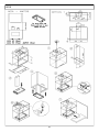
INSTALLAZIONE
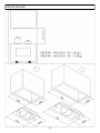
La distanza minima di sicurezza dal piano inferiore della cappa al piano di cottura deve essere di 65 cm; distanze
inferiori devono essere autorizzate esclusivamente dal costruttore (vedi disegni installazione).
La cappa può essere utilizzata sia in funzione filtrante che aspirante.
Nel funzionamento filtrante cioè con riciclo dell'aria, è necessario utilizzare dei filtri a carbone (vedere paragrafo
FILTRI CARBONE)

IT - 2
Nel funzionamento aspirante cioè con l'espulsione all'esterno dell'aria filtrata, è necessario un adeguato sistema di
compensazione secondo le norme vigenti. Il tubo di uscita dei fumi deve avere un diametro uguale o superiore rispet-
to a quello del raccordo della cappa.
Il locale dove è installata la cappa, deve disporre di sufficiente ventilazione, quando vengono utilizzati contempora-
neamente altri apparecchi che impiegano gas o altri combustibili.
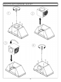
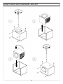
Cappe predisposte per motore remoto
Le cappe predisposte per motore remoto, sono dotate di un connettore per il collegamento con il cavo del motore
remoto. Tale connettore è posizionato all’interno della cappa. Inserire all’interno della cappa il cavo del motore remo-
to servendosi dell’apposita apertura sulla cappa (solitamente vicino al foro uscita fumi) e connettere tra loro i due
connettori. Per questa operazione fare riferimento ai disegni presenti sul libretto istruzioni dei motori remoti.
Le cappe prive di motore (Art.*0***) devono essere installate e collegate esclusivamente con l’unità aspirante forni-
ta ed indicata dal Costruttore con potenza massima 640W.
Nelle Cappe previste per l'installazione di un motore remoto, terminata l'installazione, da parte di un tecnico specia-
lizzato, tutti i cavi, connettori, i collegamenti correlati di messa a terra, del motore remoto, devono risultare non
accessibili all'utilizzatore. L'accesso ad essi deve essere possibili esclusivamente all'installatore tramite la rimozione
di pannelli fissati con viti.
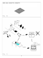
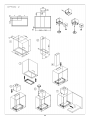
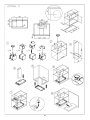
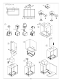
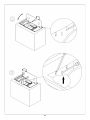
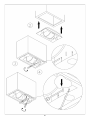
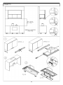
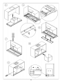
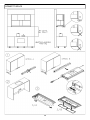
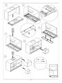
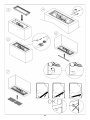
ISTRUZIONI DI MONTAGGIO
Attenzione: Prima di procedere con l’installazione, accertarsi che le viti e i tasselli forniti in dotazione, siano
idonei per il tipo di parete in cui deve essere fissata la cappa.
Per il montaggio della cappa utilizzare gli accessori in dotazione e seguire le fasi illustrate nel foglio allegato.
ALLACCIAMENTO ELETTRICO
L'allacciamento elettrico deve essere effettuato da personale specializzato, nel rispetto delle norme e leggi vigenti.
Verificare che la tensione della rete corrisponda a quella indicata sull'etichetta argentata posta all'interno
della cappa. Accertarsi che l'impianto sia realizzato secondo le norme vigenti e con lo scarico a terra efficiente.
Porre particolare attenzione al cavo di alimentazione della cappa, verificando che non attraversi fori sprovvisti di
passacavo. Nel caso di collegamento diretto alla rete, è necessario prevedere un dispositivo che assicuri la discon-
nessione dalla rete, con una distanza di apertura dei contatti che consenta la disconnessione completa nelle condizio-
ni della categoria di sovratensione III, conformemente alle regole di installazione. La spina o l'interruttore onnipolare
devono essere accessibili ad apparecchio installato. Se il cavo di alimentazione è danneggiato, esso deve essere
sostituito con un cavo speciale oppure un assieme disponibili presso il costruttore o il suo servizio assistenza tecni-
ca. Il cavo da utilizzare deve essere di tipo H05VV-F con sezione minima 3 x 0,75mm².
Il costruttore declina ogni responsabilità nel caso non vengano rispettate le norme antinfortunistiche vigenti,
necessarie al regolare funzionamento dell'impianto elettrico.
COMANDI
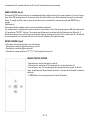
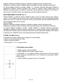
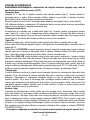
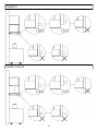
COMANDO PUSH BOTTON (Fig. 1)
Nella versione con comando pulsantiera sono presenti quattro pulsanti.
> Un pulsante per accensione e spegnimento delle luci.
> Un pulsante per accensione in 1^ velocità e spegnimento del motore.
> Un pulsante per accensione 2^ velocità.
> Un pulsante per accensione 3^ velocità.

IT - 3
COMANDO SOFT TOUCH (Fig. 2)
Nella versione con comando soft touch sono presenti quattro pulsanti a sfioramento ed un led a colore variabile
(verde min. velocità, rosso max. velocità).
> Un pulsante per accensione e spegnimento delle luci.
> Un pulsante per accensione in 2^ velocità e spegnimento del motore.
N.B. Tenendo premuto questo tasto per più di tre secondi, si attiva la funzione di autospegnimento dopo 10 minuti, il
led lampeggia lentamente.
> Due pulsanti + e - per aumento e riduzione delle velocità motore. Alla 4^ velocità del motore (intensiva) il led lam-
peggia velocemente e dopo 5min. viene impostata automaticamente la 2^ velocità.
Telecomando (option):
le cappe con il telecomando di serie sono già configurate.
Per i telecomandi optional e/o in sostituzione è necessario avviare l’apprendimento. A cappa spenta, tenere premuto
sec. il tasto “+” sulla cappa. L'apprendimento del telecomando viene segnalato con il led allarme rosso lampeggiante.
Se entro un minuto arriva un codice telecomando valido (inviato premendo qualunque tasto del telecomando), il led
diventa acceso fisso per 3 secondi per poi spegnersi, segnalando il corretto apprendimento.
COMANDO DIGITALE \ TOUCH CONTROL (Fig. 3)
Nella versione con comando digitale sono presenti cinque pulsanti a sfioramento ed un display.
> Un pulsante per accensione e spegnimento delle luci.
> Un pulsante per accensione in 2^ velocità e spegnimento del motore.
> Due pulsanti + e - per aumento e riduzione delle velocità motore. Alla 4^ velocità del motore (intensiva) il numero
presente nel display lampeggia e dopo 5min. viene impostata automaticamente la 2^ velocità.
> Un pulsante TIMER per spegnimento del motore dopo 10 min. con il timer attivato, il numero presente nel display
sarà lampeggiante
Funzioni speciali:
Dopo 100 ore di utilizzo sul DISPLAY inizierà a lampeggiare lo 0 oppure la lettera A per segnalare l'esigenza di lavare i
filtri metallici. Dopo aver lavato i filtri metallici, azzerare il conta ore tenendo premuto il tasto TIMER per più di tre
sec. con cappa spenta. La visualizzazione dell'avvenuto azzeramento viene segnalata mediante la comparsa, a cappa
spenta, di un trattino sul display.
Telecomando (option):
le cappe con il telecomando di serie sono già configurate.
Per i telecomandi optional e/o in sostituzione è necessario avviare l’apprendimento. A cappa spenta, tenere premuto
5 sec. il tasto “+” sulla cappa. L'apprendimento del telecomando viene segnalato con il display lampeggiante. Se entro
un minuto arriva un codice telecomando valido (inviato premendo qualunque tasto del telecomando), il display diventa
acceso fisso per 3 secondi per poi spegnersi, segnalando il corretto apprendimento.
COMANDO SOFT TOUCH RETROILLUMINATO (Fig. 4)
Nella versione con comando pulsantiera sono presenti sei pulsanti.
> Un pulsante per accensione in 1^ velocità e spegnimento del motore.
> Un pulsante per accensione 2^ velocità.
> Un pulsante per accensione 3^ velocità.
> Un pulsante per accensione 4^ velocità. Alla 4^ velocità del motore (intensiva) il led lampeggia velocemente e dopo
5min. viene impostata automaticamente la 2^ velocità
> Un pulsante TIMER per spegnimento del motore dopo 10 min. con il timer attivato.
> Un pulsante per accensione e spegnimento delle luci.

IT - 4
Telecomando (option):
le cappe con il telecomando di serie sono già configurate.
Per i telecomandi optional e/o in sostituzione è necessario avviare l’apprendimento. A cappa spenta, tenere premuto
5 sec. il tasto “4” sulla cappa. L'apprendimento del telecomando viene segnalato con il led lampeggiante. Se entro un
minuto arriva un codice telecomando valido (inviato premendo qualunque tasto del telecomando), il led diventa acce-
so fisso per 3 secondi per poi spegnersi, segnalando il corretto apprendimento.
COMANDO RADIO-CONTROL ( Fig. 5)
Il tasto ON/OFF sulla cappa, accende simultaneamente le luci e il motore alla seconda velocità oppure spegne tutto.
Dopo 100 ore di funzionamento del motore aspirante, inizierà a lampeggiare il led rosso a segnalare l’esigenza di
lavare i filtri metallici. Per annullare l’allarme filtri, è necessario tenere premuto a lungo il tasto ON/OFF sulla cappa
con motore spento.
Telecomando:
le cappe con il telecomando di serie sono già configurate.
Per i telecomandi optional e/o in sostituzione è necessario avviare l’apprendimento. A cappa spenta, tenere premuto
5 sec. il tasto ON/OFF sulla cappa. L'apprendimento del telecomando viene segnalato con il led allarme rosso lampeg-
giante. Se entro un minuto arriva un codice telecomando valido (inviato premendo qualunque tasto del telecomando),
il led diventa acceso fisso per 3 secondi per poi spegnersi, segnalando il corretto apprendimento.
COMANDO ROTATIVO ( Fig. 6)
Nella versione con comando rotativo sono presenti tre manopole.
> Una per accensione e spegnimento della luce decorativa.
> Una per accensione e spegnimento delle luci.
> Una per selezione 1^, 2^, 3^, 4^ velocità e spegnimento motore
TASTI TELECOMANDO
> Un tasto per accensione e spegnimento delle luci.
> Un tasto per accensione in 2^ velocità e spegnimento del motore.
> Due tasti + e - per aumento e riduzione delle velocità motore. Alla 4^ velocità del moto-
re (intensiva) il led lampeggia e dopo 5min. viene impostata automaticamente la 2^ velo-
cità.
> Un tasto TIMER per spegnimento del motore dopo 10 min.

IT - 5
USO E MANUTENZIONE
Prima di effettuare qualsiasi intervento di pulizia e manutenzione, togliere l'alimentazione alla cappa portan-
do l'interruttore generale in posizione 0 (OFF).
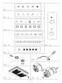
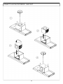
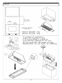
Sostituzione lampade
Alogena 12V attacco G4: Togliere mediante cacciavite, l'anello di supporto vetro (Fig. 7). Togliere il vetro e sostituire la
lampada con una identica. Rimontare il vetro di protezione e fissarlo reinserendo l'apposito anello. Le lampade posso-
no essere acquistate presso qualsiasi negozio di materiale elettrico.
Lampada dicroica attacco GU4: Togliere mediante cacciavite e sostituire la lampada con una identica (Fig. 8).
Faretto led: La sostituzione del faretto led deve essere fatta solo da tecnici qualificati utilizzando solo ricambi origi-
nali.
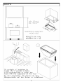
Pulizia dei filtri metallici
I filtri metallici in dotazione alla cappa vanno lavati ogni 2-3 mesi in funzione dell'intensità d'uso, con acqua calda e
detersivo liquido non aggressivo. I filtri metallici vanno tolti utilizzando l'apposita maniglia sganciando il filtro prima
nella parte anteriore tirandolo verso il basso (fig. 9).
Dopo il lavaggio i filtri devono essere completamente asciugati e rimontati correttamente.
Filtri carbone
Se la cappa è utilizzata con sistema filtrante con riciclo interno, è necessario l'impiego di filtri carbone che sono dei
contenitori di carbone attivo. Il carbone attivo contenuto nei filtri, serve a trattenere gli odori dei fumi di cucina.
Per la rimozione e sostituzione dei filtri fare riferimento alla fig. 10.
I filtri carbone POLIESTERE non possono essere rigenerati o lavati e vanno sostituiti periodicamente (ogni 4 mesi se
si utilizza la cappa per due ore al giorno). I filtri saturi di grassi infatti possono essere causa di incendi.
In base al modello di cappa, i filtri carbone possono essere di forma circolare oppure rettangolare.
I filtri carbone LONG LIFE devono essere lavati e rigenerati periodicamente. Il filtro deve essere pulito ogni due mesi
se usato normalmente. E’ preferibile lavare il filtro in lavastoviglie alla massima temperatura con detersivo normale.
Il filtro deve essere lavato da solo per evitare che le particelle di cibo entrino in esso causando successivamente un
odore sgradevole. Per riattivare il carbone attivo, il filtro deve essere asciugato in forno. Selezionare il riscaldamen-
to superiore / inferiore a massimo 100 ° C ed asciugare il filtro per 10 minuti. Il filtro deve essere sostituito quando
non è più in grado di assorbire in modo soddisfacente gli odori di cottura. Fig.11
Pulizia della cappa
La pulizia periodica delle superfici evita di dover successivamente rimuovere con difficoltà depositi di sporco incro-
stato. Se la cappa è verniciata o ramata, usare un panno morbido con acqua tiepida e detersivo neutro. E' vietato
versare liquidi direttamente sulla cappa e l'uso di prodotti granulosi e/o abrasivi. Se la cappa è in acciaio inox, usare
prodotti e panni specifici per acciaio inox satinato (non abrasivi e/o corrosivi e privi di cloro), avendo cura di seguire
col panno il verso della satinatura. Non usare prodotti aggressivi, solventi chimici o derivati da distillati di petrolio
che potrebbero lasciare residui oleosi suscettibili d'ossidazione e polimerizzazione.
Condensazione nella cappa
I piani ad induzione o vetroceramica riscaldano i cibi molto velocemente generando il vapore della cottura prima che
la superficie in vetro o in acciaio della cappa si sia riscaldata. Questo determina condensazione sulla cappa con sus-
seguente sgocciolamento. Un'altra causa di condensazione potrebbe essere che il tubo di uscita dei fumi non sia della
misura da noi consigliata (vedi paragrafo INSTALLAZIONE). Il vapore che rimane dentro alla cappa durante il raffred-
damento si condensa producendo gocciolamento. Si consiglia di accendere la cappa dieci minuti prima di iniziare a
cucinare e una volta finito, lasciarla accesa affinché tutti i fumi accumulati nel condotto possano fuoriuscire.
Inoltre è molto importante provvedere regolarmente alla pulizia dei filtri e, nel caso di deterioramento, sostituirli
(vedi PULIZIA DEI FILTRI METALLICI).
La ditta costruttrice non risponde di danni estetici causati da inosservanza delle indicazioni sopraelencate.

EN - 6
INSTRUCTIONS FOR USING, MAINTAINING AND INSTALLING THE HOOD
ATTENTION: The hood must only be installed by a qualified technician.
The company accepts no liability if it is installed by an unauthorised person.
Please read these instructions carefully before beginning the installation. Conserve this handbook together with the
hood
WARNINGS
This appliance can be used by children aged from 8 years and above and persons with reduced physical,
sensory or mental capabilities, or lack of experience and knowledge if they have been given supervision or
instruction concerning use of the appliance in a safe way and understand the hazards involved.
Children shall not play with the appliance. Cleaning and user maintenance shall not be made by children
without supervision.
Before cleaning or performing any periodic or urgent maintenance to the hood, ensure the power is turned
off by removing the plug from the socket and turning the main switch to 0 (off).
Do not connect the hood to any piping used for combustion appliances, such as burners, boilers or fire-
places.
Check that the main power supply corresponds to the voltage required by the hood, which is given on the
silver label stuck inside the hood. Ensure that the electric system is correctly earthed and that the earth
discharge works correctly.
When cooking do not use any materials that could form high or unusual flames. Oil that has been used
twice and fats are very dangerous and could easily catch fire. Do not prepare flambè dishes under the
hood.
Once the specialized technician has completed the installation of the hood equipped with a remote motor,
all the leads, connectors, ground connections and the remote motor must not be accessible to the user.
Only the installer is granted access by removing the screwed on panels.
Respect local legislation and regulations issued by the relative authorities regarding the exhaust air when
the suction is operating. Failure to respect and perform all the maintenance and cleaning operations de-
scribed in this handbook could cause a fire hazard.
CAUTION : do not stare at operating lamp. May be harmful to the eyes.
ATTENTION: Accessible parts may become hot when the hood is used with cooking appliances
INSTALLATION
The minimum safety distance between the bottom of the hood and the top of the cooking hob must be 65 cm., smaller
distances must be previously authorised by the manufacturer. (see installation drawings)
The hood can be used for both filtering and suction.
When the filtering function is operating, i.e. with air recycle, carbon filters must be used (refer to the paragraph on
CARBON FILTERS).
When the suction function is operating, i.e. exhausting the filtered air on the outside, a suitable compensation system
must be used according to current standards in force. The diameter of the fume exhaust pipe must be the same or
greater than the diameter of the hood pipe union.
There must be sufficient ventilation in the room where the hood is installed, to allow the simultaneous use of other

EN - 7
appliances that use gas or other fuel.
Hoods equipped for remote motors
The hoods equipped for remote motors have a specific connector for the remote motor lead connection. The connect-
or is situated inside the hood. Pass the remote motor lead into the hood through the aperture in the hood itself
(usually near the fume exit hole) and join the two connectors. Refer to the figures in the remote motor instruction
book when performing this operation.
Hoods without motor (Art.*0***) must only be installed and connected with extraction units with a max. output of
640W, as supplied and indicated by the manufacturer.
Once the specialized technician has completed the installation of the hood equipped with a remote motor, all the
leads, connectors, ground connections and the remote motor must not be accessible to the user. Only the installer is
granted access by removing the screwed on panels.
ASSEMBLY INSTRUCTIONS
Attention: Before proceeding with the installation, make sure that the screws and the anchors already sup-
plied, are suitable for the type of wall the hood must be fixed to.
To assemble the hood use the accessories that are supplied and follow the instructions given in the enclosed hand-
book.
ELECTRIC WIRING
The electric wiring must be performed by a specialised electrician fully respecting current standards and legislation
in force. Check that the power supply corresponds to the voltage requested by the hood, which is given on the
silver label stuck inside the hood. Ensure that the wiring system conforms to current standards and the earth
discharge works efficiently. Pay special attention to the hood power cable, ensure that it does not pass through any
holes without a cable clamp. For direct connection to the electrical mains is necessary to provide a device that en-
sures disconnection from the electrical mains, with an opening distance of the contacts that allows the complete
disconnection under the conditions ofovervoltage category III, in accordance with the rules of installation.
The plug or omnipolar switch must be accessible when the unit is installed
If the power cord is damaged, it must be replaced by a special cord or assembly available from the manufacturer or
its service agent. The cable used must be of type H05VV-F 3 x 0.75 mm2 minimum cross-section.
The manufacturer declines all responsibility if the current accident prevention standards in force are not
respected, which are needed for the wiring system to operate correctly
CONTROLS
KEYBOARD CONTROLS (Fig. 1)
There are four buttons on the keyboard control version:
> One for turning the lights on and off.
> One for turning the motor on at 1st speed and for turning it off.
> One for turning it on at 2nd speed.
> One for turning it on at 3rd speed.
SOFT TOUCH CONTROL (Fig. 2)
There are four soft touch buttons on this version and a variable colour led (green min. speed, red max. speed).
> One button for turning the lights on and off.

EN - 8
> One button for turning on at 2nd speed and for turning the motor off.
N.B. If this button is kept depressed for more than three seconds, the automatic function is activated to turn the hood
off function after 10 minutes, the led flashes slowly .
> Two buttons + and - for increasing and reducing the motor speed. At the 4th motor speed (intense) the led flashes
quickly and after 5 minutes the 2nd speed is automatically set.
Remote control (option):
The hoods with the standard remote control are already configured.
For optional and/or replacement remote controls it is necessary to start the learning process. With the hood turned
off, keep button “+” for 5sec. The remote control learning is indicated with the flashing alarm filters led. If within one
minute arrive a valid remote control code (sent by pressing any button of the remote control ) the led will be on
continuously for 3 seconds and then it will turn off, indicating the proper learning.
DIGITAL CONTROLS \ TOUCH CONTROLS (Fig. 3)
In this version there are five soft touch buttons and a display
> One button for turning the lights on and off.
> One button for turning on at 2nd speed and for turning the motor off.
> Two buttons + and - for increasing and decreasing the motor speed. At the 4th motor speed (intense) the number
on the display flashes and after 5 minutes the 2nd speed is automatically set.
> A TIMER button for turning the motor off after 10 minutes. When the timer is activated, the number on the display
flashes.
Special functions:
After 100 hours use, a 0 or a letter A will start flashing on the DISPLAY to remind the user to clean the metal filters.
After washing the metal filters, reset the hour meter by pressing the TIMER button for more than three seconds with
the hood turned off. When the hour meter has been reset a dash appears on the display, with the hood turned off.
Remote control (option):
The hoods with the standard remote control are already configured.
For optional and/or replacement remote controls it is necessary to start the learning process. With the hood turned
off, keep button “+” for 5sec. The remote control learning is indicated with the flashing alarm filters led. If within one
minute arrive a valid remote control code (sent by pressing any button of the remote control ) the led will be on
continuously for 3 seconds and then it will turn off, indicating the proper learning.
SOFT TOUCH CONTROL BACKLIT (Fig. 4)
There are six buttons on this version:
> One for turning the motor on at 1st speed and for turning it off.
> One for turning it on at 2nd speed.
> One for turning it on at 3rd speed.
> One for turning it on at 4th speed. At the 4th motor speed (intense) the led flashes quickly and after 5 minutes the
2nd speed is automatically set.
> TIMER button for turning the motor off after 10 minutes.
> One for turning the lights on and off.
Remote control (option):
The hoods with the standard remote control are already configured.
For optional and/or replacement remote controls it is necessary to start the learning process. With the hood turned
off, keep button “ 4 ” for 5sec. The remote control learning is indicated with the flashing alarm filters led. If within one
minute arrive a valid remote control code (sent by pressing any button of the remote control ) the led will be on

EN - 9
continuously for 3 seconds and then it will turn off, indicating the proper learning.
RADIO- CONTROL (Fig. 5)
The button ON/OFF on the hood turn on simultaneously lights and the motor at the second speed or it turns off every-
thing. After 100 working hours of the suction motor the red led will start to flash indicating the need to wash metals
filters. To cancel the filters alarm, when the suction motor is switched off, you must press button ON/OFF long
enough.
Radio control:
The hoods with the standard remote control are already configured.
For optional and/or replacement remote controls it is necessary to start the learning process. With the hood turned
off, keep button “ON/OFF” for 5sec. The remote control learning is indicated with the flashing alarm filters led. If
within one minute arrive a valid remote control code (sent by pressing any button of the remote control ) the led will
be on continuously for 3 seconds and then it will turn off, indicating the proper learning.
ROTARY CONTROL (Fig.6)
In the rotary control version there are three knobs:
> One knob for switching light decorative on and off
> One knob for switching lights on and off
> One knob for speed selection (1^,2^,3^,4^) and turning the motor off.
REMOTE CONTROL BUTTONS
> One button for turning the lights on and off.
> One button for turning on at 2nd speed and for turning the motor off.
> Two buttons + and - for increasing and decreasing the motor speed. At the 4th
motor speed (intense) the led flashes and after 5 minutes the 2nd speed is automat-
ically set.
> A TIMER button for turning the motor off after 10 minutes.

EN - 10
USE AND MAINTENANCE
Before beginning any sort of cleaning or maintenance work, turn power off to the hood by turning the main
switch to 0 (OFF).
Changing the light bulbs
12V halogen G4 attachment: Use a screwdriver to unscrew the glass support ring (Fig. 7). Remove the glass and chan-
ge the light bulb with another identical. Replace the protective glass and screw back the ring. The light bulbs can be
purchased in any electrical supply shop.
Dichroic lamp G4 attachment: Use a screwdriver to remove and change the dichroic lamp with another identical (Fig.
8).
LED spotlight replacement should only be carried out by qualified technicians using only original spare parts.
Cleaning the metal filters:
The metal filters fitted in the hood should be washed every 2-3 months, depending on how much the hood is used,
using hot water and a liquid detergent that is not too aggressive. The metal filters can be removed by the special
handle, unhooking the front part of the filter and pulling it downwards (Fig. 9)
Carbon filters
If the hood is used with an internal recycle filtering system, then active carbon filters must be used. The active car-
bon in the filters traps the cooking smells. To remove and change the filters, refer to fig. 10.
POLYESTER carbon filters cannot be reused or washed and must be periodically changed (every 4 months if the hood
is used for 2 hours every day). Saturate filters could be a fire hazard. Depending on the hood model, the carbon fil-
ters are round or rectangular.
LONG LIFE carbon filter can be cleaned and reactivated. The filter should be cleaned every other month if used nor-
mally. The filter is best cleaned in a dishwasher at the highest temperature using normal washer detergent. The filter
should be washed on its own to prevent particles of food from fastening in it and then causing an unpleasant smell
later on. To reactivate the carbon the filter should be dried in the oven. Chose upper/ lower heat and maximum 100 °
C and try the filter for 10 minutes. The filter must be changed when it no longer absorbs the cooking smells suffi-
ciently. (fig.11)
Cleaning the hood
The surfaces of the hood should be cleaned frequently, to avoid the risk of having to remove built up and encrusted
deposits and stains.
For the painted or copper plated hoods just use a soft cloth with warm water and a neutral detergent. Do not pour the
detergent directly onto the hood or use powdery or abrasive products
For the stainless steel hood, use special products and cloths for satin finish stainless steel (not abrasive, corrosive
detergents or detergents containing chloride), ensuring to clean in the same direction as the satin finish.
Do not use aggressive products, chemical solvents or derivatives of oil distillates that could leave oily traces which
could cause oxidation and polymerisation.
Condensation in the hood
Induction or glass ceramic hobs heat food up very quickly, creating cooking steam before the glass or steel surface
of the hood has heated up, which causes condensation on the hood that then drips. Another cause for condensation
could be that the fume pipe is not the size we recommend (see INSTALLATION). The steam that remains inside the
hood while it is cooling down condensates and drips. Therefore it is advisable to turn the hood on ten minutes before
starting to cook and when you have finished, leave it on so that all the fumes in the pipe are expelled.
Furthermore, it is important to clean the filters frequently and if they are worn they should be replaced (see CLEAN-
ING THE METAL FILTERS).
The manufacturer accepts no responsibility for damage to the surface of the hood due to failure to respect
these instructions.

DE - 11
BEDIENUNGS-, WARTUNGS- UND INSTALLATIONSHANDBUCH ABZUGSHAUBE
ACHTUNG! Die Abzugshaube darf ausschließlich von qualifiziertem Fachpersonal installiert werden. Bei Installation durch un-
qualifiziertes Personal übernimmt der Hersteller keinerlei Haftung! Vor der Installation der Abzugshaube muss das
vorliegende Handbuch aufmerksam gelesen werden. Das vorliegende Handbuch muss während der gesamten Lebensdauer der
Abzugshaube aufbewahrt werden.
WICHTIGE HINWEISE
Das Gerät darf von Kindern unter 8 Jahren und von körperlich, geistig oder sensoriell gestörten oder unerfahrenen
Personen nur dann verwendet werden, wenn sie beaufsichtigt sind oder wenn sie über den sicheren Gebrauch ges-
chult wurden und von den Gefahren während der Benutzung des Gerätes Kenntnis genommen und verstanden haben.
Kinder dürfen nicht mit dem Gerät spielen.
Die Reinigung und Wartung, die durch den Gebraucher durchgeführt werden müssen, dürfen nicht von Kindern ohne
Aufsicht durchgeführt werden.
Vor Durchführung von Reinigungs- oder Wartungsarbeiten (ordentliche oder außerordentliche Wartung) muss der
Strom an der Abzugshaube abgeschaltet werden. Dazu den Netzstecker abziehen oder den Hauptschalter der Abzugs-
haube auf 0 (OFF) stellen.
Die Abzugshaube nicht an Rohrleitungen anschließen, die von Verbrennungsapparaten wie Brenner, Heizungen oder
Kamine benützt werden. Sicherstellen, dass die Netzspannung mit den Angaben auf dem silbernen Typenschild in der
Abzugshaube übereinstimmt. Sicherstellen, dass die elektrische Anlage korrekt geerdet ist. Beim Kochen keine Sub-
stanzen verwenden, die hohe oder anomale Flammen erzeugen können.
Öl, das bereits benützt worden ist, und Fette sind besonders gefährlich und können in Brand geraten.
Für die für die Installation eines Außenmotors vorgesehenen Hauben, dürfen, nach der Installation durch einen
Fachtechniker, alle Kabel, Verbindungsstecker und alle die mit der Erdung verbundenen Teile vom Benutzer nicht
zugänglich sein. Der Zugang zu diesen Teilen soll ausschließlich nur für den Installateur, durch Entfernung der mit
Schrauben befestigten Platten, möglich sein.
Unter der Abzugshaube dürfen keine flambierten Speisen zubereitet werden.
Die am Installationsort geltenden und von den lokalen Behörden vorgegebenen Vorschriften zur Luftableitung müssen
für die eingeschaltete Abzugshaube beachtet werden. Es wird ausdrücklich darauf hingewiesen, dass ernsthafte
Brandgefahr besteht, wenn die im vorliegenden Handbuch beschriebenen Wartungsarbeiten nicht ordnungsmäßig
durchgeführt werden.
Acthung: Nicht bei Betriebs Lamp blicken. Das kann schädlich fur die Augen.
Achtung: Die zugänglichen Teile können warm werden, wenn die Haube mit Kochgeräten benutzt wird.
INSTALLATION
Der Sicherheitsabstand zur Unterkante der Abzugshaube zum Kochfeld muss mindestens 65 cm betragen. Geringere Abstände
müssen ausdrücklich vom Hersteller genehmigt werden. (Siehe Einrichtungszeichnung) .Die Abzugshaube kann in der Betriebsart
Filtern und in der Betriebsart Absaugen verwendet werden. In der Betriebsart Filter mit Rückführung der Luft müssen Kohlen-
stofffilter verwendet werden (siehe Abschnitt KOHLENSTOFFFILTER). In der Betriebsart Absaugen mit Ableitung der gefilterten Luft
nach außen ist ein angemessenes Ausgleichssystem nach Vorgabe der geltenden Vorschriften erforderlich. Der Durchmesser
vom Abzugsrohr muss gleich groß oder größer als der Anschluss sein. Der Raum, in dem die Abzugshaube installiert wird, muss
ausreichend belüftet sein, wenn gleichzeitig andere Geräte benützt werden, die mit Gas oder anderen Brennstoffen betrieben

DE - 12
werden.
Hauben für Außenmotore.
Die für Außenmotore vorbereiteten Hauben sind mit einem Verbindungsstecker für den Kabelanschluss am Außenmotor ausges-
tattet. Dieser Verbindungsstecker befindet sich innerhalb der Haube. Das Kabel für den Außenmotor durch die dafür bestimmte
Öffnung an der Haube (üblicherweise in der Nähe der Rauchablassöffnung) ziehen und die beiden Stecker miteinander verbinden.
Für diesen Vorgang verweisen wir auf die entsprechende Zeichnung in der Gebrauchsanweisung der Außenmotore.
Die Hauben ohne Motor (Art.*0***) müssen ausschließlich mit der vom Hersteller gelieferten und angegebenen Ansaugeinheit mit
einer maximalen Leistung von 640 W installiert und angeschlossen werden.
Für die für die Installation eines Außenmotors vorgesehenen Hauben, dürfen, nach der Installation durch einen Fachtechniker, alle
Kabel, Verbindungsstecker und alle die mit der Erdung verbundenen Teile vom Benutzer nicht zugänglich sein. Der Zugang zu diesen
Teilen soll ausschließlich nur für den Installateur, durch Entfernung der mit Schrauben befestigten Platten, möglich sein.
MONTAGEANLEITUNG
Achtung! Falls die Schrauben und Dϋbel mit dem rodukt mitgeliefert curde, sich vergewissern, daβ sie fϋr die Art der
Wand, an der die Abzugshaube befestigt werden soll, geeignet sind. Für die Montage der Abzugshaube das mitgelieferte
Zubehör verwenden und wie auf dem beiliegenden Informationsblatt dargestellt vorgehen.
STROMANSCHLUSS
Der Stromanschluss darf ausschließlich von einem qualifizierten Elektriker durchgeführt werden und muss unter Beachtung der
am Installationsort geltenden Vorschriften erfolgen.
Sicherstellen, dass die Netzspannung mit den Angaben auf dem silbernen Typenschild in der Abzugshaube überein-
stimmt. Sicherstellen, dass die elektrische Anlage unter Beachtung der geltenden Gesetzgebung und mit einer ordnungsmäßigen
Erdung ausgeführt worden ist. Das Stromkabel der Abzugshaube muss besonders sorgfältig verlegt werden und darf auf keinen
Fall durch Löcher geführt werden, die keine Kabelführung haben.
Wird das Gerät direkt an das Stromnetz angeschlossen, muss eine Vorrichtung vorgesehen werden, die eine Trennung vom Strom-
netz, mit einem Öffnungsabstand der Kontakte, die eine komplette Abtrennung in den Zuständen der Überspannungskategorie III,
entsprechend der Installationsvorschriften, ermöglicht, gewährleistet.
Der Stecker bzw. der allpolige Schalter muss bei installiertem Gerät zugänglich sein.
Ist das Versorgungskabel beschädigt, muss es gegen ein neues Spezialkabel oder gegen einen beim Hersteller bzw. beim
Kundendienst erhältlichen Satz ausgewechselt werden. Es muss ein Kabel vom Typ H05VV-F mit Mindestquerschnitt 3 x 0,75mm²
verwendet werden.
Bei Nichtbeachtung der am Installationsort geltenden Sicherheitsvorschriften, die für ein ordnungsmäßiges Funktion-
ieren der elektrischen Anlage erforderlich sind, übernimmt der Hersteller keinerlei Haftung.
STEUERUNG
STEUERUNG TASTENFELD (Abb. 1)
In der Ausführung mit Tastenfeld ist das Gerät mit vier Tasten ausgestattet, davon:
> eine Taste zum Ein- und Ausschalten der Beleuchtung.
> eine Taste zum Einschalten der 1. Geschwindigkeitsstufe und zum Ausschalten vom Motor.
> eine Taste zum Einschalten der 2. Geschwindigkeitsstufe.
> eine Taste zum Einschalten der 3. Geschwindigkeitsstufe.

DE - 13
SOFT TOUCH STEUERUNG (Abb. 2)
In der Ausführung mit Soft Touch ist das Gerät mit vier Schaltflächen und einer Kontrollleuchte ausgestattet, die grün
(Mindestgeschwindigkeit) oder rot (Höchstgeschwindigkeit) aufleuchtet, davon:
> eine Schaltfläche zum Ein- und Ausschalten der Beleuchtung.
> eine Schaltfläche zum Einschalten der 2. Geschwindigkeitsstufe und zum Ausschalten vom Motor.
HINWEIS. Wenn diese Schaltfläche länger als 3 Sekunden gedrückt wird, wird die Selbstabschaltung nach Ablauf von 10 Minuten
aktiviert, die LED blinkt langsam.
> zwei Schaltflächen + und - zum Erhöhen und Verringern der Motorgeschwindigkeit. Bei der 4. Geschwindigkeit des Motors
(intensiv) wird die LED schleunig blinken und nach 5 Minuten wird automatisch die 2. Geschwindigkeit eingestellt
Fernbedienung (Option):
Die Hauben mit seruenmäßig gelieferter Fernsteiurrung sind schon konfiguriert.
Für die als Optional bzw. als Ersatz gelieferte Fernsteuerung muss die Anerkennung gestartet werden. Bei ausgeschalteter Haube
5 Sekunden die Taste “ + “ drücken. Die korrekte Einstellung der Fernbedienung wird durch die an/aus blickendes rote LED Leuch-
te bestätigt. Wenn innerhalb einer Minute ein gültiges Code empfangen wird (gesendet indem man eine beliebige Taste der Fern-
bebdienung drückt), geht die LED Leuchte fix 3 Sekunden an und signalisiert somit die richtige Einstellung.
DIGITALE STEUERUNG \ TOUCH STEUERUNG (Abb. 3)
In der Ausführung mit digitaler Steuerung ist das Gerät mit fünf Schaltflächen und einem Display ausgestattet, davon:
> eine Schaltfläche zum Ein- und Ausschalten der Beleuchtung.
> eine Schaltfläche zum Einschalten der 2. Geschwindigkeitsstufe und zum Ausschalten vom Motor.
> zwei Schaltflächen + und - zum Erhöhen und Verringern der Motorgeschwindigkeit. Bei der 4. Geschwindigkeit des Motors
(intensiv) wird die auf dem Display sichtbare Nummer blinken und nach 5 Minuten wird automatisch die 2. Geschwindigkeit
eingestellt.
> eine Schaltfläche TIMER zum Abschalten vom Motor nach Ablauf von 10 Minuten. Wenn der Timer eingeschaltet ist, blinkt die Zahl
auf dem Display.
Sonderfunktionen:
Nach 100 Betriebsstunden beginnt auf dem DISPLAY eine 0 oder der Buchstabe A zu blinken und zeigt an, dass die Metallfilter
sauber gemacht werden müssen. Nach dem Saubermachen der Metallfilter den Betriebsstundenzähler auf Null stellen und dazu
die Schaltfläche TIMER bei abgeschalteter Abzugshaube 3 Sekunden lang drücken. Die Nullstellung vom Zähler wird durch die
Anzeige eines Bindestrichs auf dem Display bei abgeschalteter Abzugshaube bestätigt.
Fernbedienung (Option):
Die Hauben mit seruenmäßig gelieferter Fernsteiurrung sind schon konfiguriert.
Für die als Optional bzw. als Ersatz gelieferte Fernsteuerung muss die Anerkennung gestartet werden. Bei ausgeschalteter Haube
5 Sekunden die Taste “ + “ drücken. Die korrekte Einstellung der Fernbedienung wird durch die an/aus blickendes rote LED Leuch-
te bestätigt. Wenn innerhalb einer Minute ein gültiges Code empfangen wird (gesendet indem man eine beliebige Taste der Fern-
bebdienung drückt), geht die LED Leuchte fix 3 Sekunden an und signalisiert somit die richtige Einstellung.
SOFT TOUCH STEUERUNG HINTERLEUCHTET (Abb. 4)
In der Ausführung mit Tastenfeld ist das Gerät mit sechs Tasten ausgestattet, davon:
> eine Taste zum Einschalten der 1. Geschwindigkeitsstufe und zum Ausschalten vom Motor.
> eine Taste zum Einschalten der 2. Geschwindigkeitsstufe.
> eine Taste zum Einschalten der 3. Geschwindigkeitsstufe.
> eine Taste zum Einschalten der 4. Geschwindigkeitsstufe. Bei der 4. Geschwindigkeit des Motors (intensiv) wird die LED schleunig
blinken und nach 5 Minuten wird automatisch die 2. Geschwindigkeit eingestellt
> eine Schaltfläche TIMER zum Abschalten vom Motor nach Ablauf von 10 Minuten.

DE - 14
> eine Taste zum Ein- und Ausschalten der Beleuchtung.
Fernbedienung (Option):
Die Hauben mit seruenmäßig gelieferter Fernsteiurrung sind schon konfiguriert.
Für die als Optional bzw. als Ersatz gelieferte Fernsteuerung muss die Anerkennung gestartet werden. Bei ausgeschalteter Haube
5 Sekunden die Taste “ 4 “ drücken. Die korrekte Einstellung der Fernbedienung wird durch die an/aus blickendes rote LED Leuch-
te bestätigt. Wenn innerhalb einer Minute ein gültiges Code empfangen wird (gesendet indem man eine beliebige Taste der Fern-
bebdienung drückt), geht die LED Leuchte fix 3 Sekunden an und signalisiert somit die richtige Einstellung.
RADIOSTEUERUNG (Abb. 5)
Die Taste ON/OFF schaltet die Lichter an und gleichzeitig den Motor (zweiten Geschwindigkeit) oder schaltet beides aus. Nach 100
Stunden Motorfunktion beginnt die rot LED Lampe an zu leuchten was auf eine Reinigung der Filter hinweist. Um Filterhallarm
abzustellen ist es notwendig die Taste ON/OFF längere Zeit zu drücken, bei abgeschaltetem Motor.
Fernbedienung:
Die Hauben mit seruenmäßig gelieferter Fernsteiurrung sind schon konfiguriert.
Für die als Optional bzw. als Ersatz gelieferte Fernsteuerung muss die Anerkennung gestartet werden. Bei ausgeschalteter Haube
5 Sekunden die Taste “ ON/OFF “ drücken. Die korrekte Einstellung der Fernbedienung wird durch die an/aus blickendes rote LED
Leuchte bestätigt. Wenn innerhalb einer Minute ein gültiges Code empfangen wird (gesendet indem man eine beliebige Taste der
Fernbebdienung drückt), geht die LED Leuchte fix 3 Sekunden an und signalisiert somit die richtige Einstellung.
DREHENDE STEUERUNG (Fig.6)
In der Ausführung mit drehende Steuerung ist das Gerät mit zwei Tasten ausgestatten von :
> eine für das Ein und Ausschalten des dekorativen Licht
> eine Taste zum Ein – Ausschalten der Berechtung
> eine Taste um die Geschwindigkeit 1 ^ 2^ 3^ 4^ zu auswählen.
Fernbedienung tastatur
> eine Schaltfläche zum Ein- und Ausschalten der Beleuchtung.
> eine Schaltfläche zum Einschalten der 2. Geschwindigkeitsstufe und zum Ausschalten vom
Motor.
> zwei Schaltflächen + und - zum Erhöhen und Verringern der Motorgeschwindigkeit. Bei der 4.
Geschwindigkeit des Motors (intensiv) wird die LED blinken und nach 5 Minuten wird automatisch
die 2. Geschwindigkeit eingestellt.
> eine Schaltfläche TIMER zum Abschalten vom Motor nach Ablauf von 10 Minuten.

DE - 15
GEBRAUCH UND WARTUNG
Vor Durchführung von Reinigungs- oder Wartungsarbeiten gleich welcher Art muss der Strom an der Abzugshaube
abgeschaltet werden. Dazu den Hauptschalter der Abzugshaube auf 0 (OFF) stellen.
Auswechseln der Birnen
Halogenbirne 12 V mit Fassung G4: Mit einem Schraubenzieher die Halterung der Scheibe (Abb. 7) abmachen. Die Scheibe abmachen und
die Birne durch eine gleichwertige Birne ersetzen. Die Scheibe wieder anbringen und mit dem Ring sichern. Es handelt sich um handelübli-
che Birnen, die überall erhältlich sind.
Dichroitische Birne mit Fassung GU4: Mit einem Schraubenzieher herausnehmen und durch eine gleichwertige Birne ersetzen (Abb. 8).
Im Bedarfsfall darf der LED-Strahler nur von qualifizierten Technikern unter Verwendung von originalen Ersatzteilen ausgeführt werden.
Reinigung der Metallfilter
Die Metallfilter der Abzugshaube müssen alle 2-3 Monate mit heißem Wasser und einem milden Reinigungsmittel gewaschen werden, je
nachdem wie oft die Abzugshaube benützt wird. Zum Herausnehmen der Metallfilter die Filter am Griff anfassen und durch Ziehen nach
unten zuerst vorne und dann hinten aus ihrem Sitz lösen (Abb. 9). Die Filter erst dann wieder einsetzen, wenn sie vollständig getrocknet
sind.
Kohlenstofffilter
Wenn die Abzugshaube mit Filtersystem mit interner Rückführung benützt wird, müssen Kohlenstofffilter verwendet werden. Bei diesen
Filtern handelt es sich um Behälter, die Aktivkohle enthalten. Die Aktivkohle in den Filtern hält die Küchendünste zurück. Für die Beseitigung
oder Austausch der Filter Siehe Abbildung 10.
Die POLYESTER Kohlenstofffilter können nicht wiederverwertet oder gewaschen werden, sondern müssen regelmäßig ausgewechselt
werden, und zwar alle 4 Monate, wenn die Abzugshaube zwei Stunden täglich benützt wird. Mit Fett verschmutzte Filter stellen eine
Brandgefahr dar! Je nach Modell kann die Abzugshaube mit runden oder rechteckigen Kohlenstofffiltern ausgestattet sein.
Im Unterschied zu anderen Kohlefiltern kann der LONG LIFE. Kohlefilter gereinigt und reaktiviert werden. Bei normaler Nutzung der Abzu-
ghaube sollte der Filter jeden zweiten Monat gereinigt werden. Der Filter wird am besten in der Spülmaschine gereinigt. Normalen Reiniger
verwenden un die höchste Temperatur wählen. Der Filter sollte separate gespült werden , damit sich keine Speisereste am Filter festse-
tzen und spatër schlechte Gerüche verursachen können. Um die Kohle wieder zu aktivieren, muβ der Filter im Backhofen getrocknet
werden . Ober – und Unterhitze sowie eine Temperatur von maximal 100 ° C wählen und den Filter 10 Minuten lang trocken. Der Filter muss
ausgewechselt werden, sobald er nicht mehr in der Lage ist die Küchengerüche aufzunehmen. (Abb.11)
Reinigung der Abzugshaube
Eine regelmäßige Reinigung der Oberflächen vermeidet eine spätere schwierige Entfernung von sich angesetzten Verkrustungen. Lack-
ierte oder verkupferte Abzugshauben mit einem weichen Lappen und etwas warmem Wasser und neutralem Reinigungsmittel sauber
machen. Es ist verboten, Flüssigkeiten direkt auf die Abzugshaube zu schütten! Keine Scheuermittel verwenden! Abzugshauben aus Edel-
stahl mit Spezialprodukten für matte Edelstahlflächen sauber machen (keine Scheuermittel, ätzende Produkte oder chlorhaltigen Produkte
verwenden). Dabei darauf achten, dass mit dem Lappe in Richtung der Oberflächenstruktur gewischt wird. Keine aggressiven Produkte,
chemischen Lösungsmittel oder Produkte auf Erdölbasis verwenden, da diese ölige Rückstände hinterlassen, die oxydieren oder polymer-
isieren können.
Kondensation in der Haube
Die Induktions- oder Glaskeramikflächen erhitzen die Speisen sehr schnell und erzeugen Kochdampf noch bevor sich die Oberflächen der
Glas- bzw. Stahlhaube erwärmt haben. Dieser Vorgang bildet Kondenswasser mit darauffolgendem Tropfen. Ein anderer Grund der
Kondensation könnte sein, dass das Rauchablassrohr nicht den von uns empfohlenen Abmessungen entspricht (siehe Paragraf INSTALLA-
TION). Der in der Haube, während der Abkühlung, zurückbleibende Dampf kondensiert sich und bildet Tropfen. Wir empfehlen die Haube
zehn Minuten vor dem Kochen einzuschalten und sie, nach Beendung des Kochens, eingeschaltet lassen, damit der ganze sich in der
Rohrleitung angesammelte Rauch ausströmen kann. Außerdem ist eine regelmäßige Reinigung der Filter sehr wichtig, und dass diese, falls
sie sich verschlechtert haben sollten, ausgewechselt werden (siehe REINIGUNG DER METALLFILTER).
Der Hersteller ist nicht für Beeinträchtigungen vom Aussehen der Abzugshaube haftbar, die durch Nichtbeachtung der oben
stehenden Hinweise entstanden sind.

FR - 16
INSTRUCTIONS POUR L’UTILISATION, L’ENTRETIEN ET L’INSTALLATION DE LA HOTTE.
Attention: La hotte doit être installée uniquement par du personnel habilité.
On décline toute responsabilité au sujet d’installations effectuées par des personnes sans habilitation.
Avant de procéder à l'installation de la hotte, lire attentivement et intégralement ces instructions. Le présent livret doit être
conservé pendant toute la vie de la hotte.
AVERTISSEMENTS
L'appareil peut être utilisé par des enfants ayant au moins 8 ans et par des personnes ayant des capacités phy-
siques, sensorielles ou mentales réduites, ou sans expérience ou les connaissances nécessaires, à condition
qu'ils soient surveillés ou qu'ils aient reçu les instructions nécessaires à l'utilisation en toute sécurité de l'appa-
reil et à la compréhension des dangers qui y sont liés. Les enfants ne doivent pas jouer avec l'appareil. Le nettoy-
age et l'entretien destiné à être effectué par l'utilisateur ne doit pas être effectué par des enfants sans surveil-
lance.
Avant de procéder au nettoyage ou à l’entretien (périodique ou extraordinaire) toujours couper l'alimentation
électrique de la hotte en détachant la fiche ou en agissant sur l’interrupteur général en l’amenant en position 0
(OFF).
Ne pas relier la hotte à des conduits utilisés pour des appareils à combustion comme des brûleurs, des
chaudières ou des cheminées. Vérifier que la tension du réseau correspond à ce qui est prévu sur l’étiquette
argentée placée à l’intérieur de la hotte. S’assurer que l’installation électrique est réalisée avec la mise à la terre
et que celle-ci est efficace. Ne pas utiliser pour la cuisson des matériaux qui peuvent développer des flammes
hautes ou quoi qu’il en soit anomales.
L'huile utilisée deux fois et les graisses sont particulièrement dangereuses et pourraient s’enflammer.
Il est interdit de préparer des aliments flambés sous la hotte.
Dans les hottes prévues pour l'installation d'un moteur à distance, une fois terminée l'installation, de la part d'un
technicien spécialisé, tous les câbles, connecteurs, les raccordements raccordés à la mise à la terre, ne doivent
pas être accessibles pour l'utilisateur. L'accès à ces derniers ne doit être possible que pour l'installateur moy-
ennant la dépose de panneaux fixés avec des vis.
Respecter les normes locales en vigueur et les prescriptions des autorités compétentes relatives à l’évacuation
de l’air dans le fonctionnement aspirant de la hotte. On rappelle que si jamais toutes les opérations d’entretien
citées dans le présent opuscule ne sont respectées et effectuées, il existe de sérieux risques d’incendie.
Attention: ne jamais fixer la lampe quand elle est allumée ; cela peut être dangereux pour les yeux.
Attention: Les parties accessibles peuvent devenir chaudes quand la hotte est utilisée avec des appareils de
cuisson.
INSTALLATION
La distance minimum de sécurité du niveau inférieur de la hotte au plan de cuisson doit être de 65 cm; des distances inféri-
eures doivent être autorisées exclusivement par le constructeur. (voir dessins d’installation). La hotte peut être utilisée aussi
bien en fonction filtrante qu’aspirante. Dans le fonctionnement filtrant c’est-à-dire avec recyclage de l’air, il est nécessaire
d’utiliser des filtres au carbone (voir paragraphe FILTRES CARBONE) Dans le fonctionnement aspirant, c’est-à-dire avec
l’expulsion à l’extérieur de l’air filtré, il est nécessaire d’avoir un système adéquat de compensation selon les normes en
vigueur. Le tuyau de sortie des fumées doit avoir un diamètre égal ou supérieur à celui du raccord. Le local où est installée la

FR - 17
hotte, doit disposer d’une ventilation suffisante, quand sont utilisés en même temps d’autres appareils qui emploient du gaz
ou d’autres combustibles.
Hottes prévues pour moteur à distance
Les hottes prévues pour moteur à distance, sont équipées d'un connecteur pour le raccordement avec le câble du moteur à
distance. Ce connecteur se trouve à l'intérieur de la hotte. Insérer à l'intérieur de la hotte le câble du moteur à distance en se
servant de l'ouverture prévue à cet effet sur la hotte (elle se trouve d'habitude près du trou de sortie des fumées) et con-
necter les deux connecteurs entre eux. Pour cette opération se reporter aux dessins qui se trouvent sur le livret d'instruc-
tions des moteurs à distance.
Les hottes sans moteur (Art.*0***) doivent être installées et raccordées uniquement avec l'unité aspirante fournie et indi-
quée par le Constructeur avec puissance maximale 640W.
Dans les hottes prévues pour l'installation d'un moteur à distance, une fois terminée l'installation, de la part d'un technicien
spécialisé, tous les câbles, connecteurs, les raccordements raccordés à la mise à la terre, ne doivent pas être accessibles
pour l'utilisateur. L'accès à ces derniers ne doit être possible que pour l'installateur moyennant la dépose de panneaux fixés
avec des vis.
INSTRUCTIONS DE MONTAGE
Attention: Avant de procéder à l'installation, assurez-vous que les vis et ancrages fournis sont adaptés au type de
mur où la hotte doit être fixé. Pour le montage de la hotte utiliser les accessoires en dotation et suivre les phases illus-
trées dans la feuille jointe.
RACCORDEMENT ELECTRIQUE
Le raccordement électrique doit être effectué par du personnel spécialisé, dans le respect des normes et des lois en vigueur.
Vérifier que la tension du réseau correspond à celle indiquée sur l’étiquette argentée placée à l’intérieur de la
hotte. S’assurer que l’installation est réalisée selon les normes et que la mise à la terre est efficace. Prêter une attention
particulière au câble d’alimentation de la hotte, en vérifiant qu’il ne traverse pas de trous dépourvus de passe-fils. Avec la
connexion au réseau, il est nécessaire de prévoir un dispositif garantissant la déconnexion du réseau, avec une distance
d'ouverture des contacts permettant la déconnexion complète dans les conditions de la catégorie de surtension III, con-
formément aux règles d'installation. La fiche ou l'interrupteur omnipolaire doivent être accessibles avec l'appareil installé. Si
le câble d'alimentation est endommagé, il doit être remplacé par un câble spécial ou bien par un ensemble disponible chez le
fabricant ou son service d'assistance technique. Le câble à utiliser doit être du type H05VV-F avec section minimum 3 x
0,75mm².
Le constructeur décline toute responsabilité au cas où ne seraient pas respectées les règles de prévention des
accidents en vigueur, nécessaires au fonctionnement régulier de l’installation électrique.
COMMANDES
COMMANDE PAR TABLEAU A POUSSOIRS (Fig. 1)
Dans la version avec commande par tableau à poussoirs sont présents quatre poussoirs.
> Un poussoir pour allumage et extinction des lumières.
> Un poussoir pour allumage en 1^ vitesse et extinction du moteur.
> Un poussoir pour allumage 2^ vitesse.
> Un poussoir pour allumage 3^ vitesse.

FR - 18
COMMANDE SOFT TOUCH (Fig. 2)
Dans la version avec commande soft touch sont présents quatre poussoirs à effleurement et une led de couleur
variable (vert vitesse min., rouge vitesse max.).
> Un poussoir pour allumage et extinction des lumières.
> Un poussoir pour allumage en 2^ vitesse et extinction du moteur.
N.B. En maintenant ce poussoir enfoncé pendant plus de trois secondes, on active la fonction d’extinction automa-
tique après 10 minutes, la led clignote lentement .
> Deux poussoirs + et – pour l’augmentation et la réduction des vitesses moteur. À la 4^ vitesse du moteur
(intensive) la led clignote rapidement et après 5 minutes la 2^ vitesse s’enclenche automatiquement.
Télécommande (option):
les hottes avec la télécommande sont déjà configurées.
Pour les télécommandes en option et/ou en remplacement l’apprentissage est nécessaire. Avec la hotte arrêtée,
appuyer pendant 5 sec. sur la touche “ + “ située sur la hotte. L’apprentissage de la télécommande est signalé par la
LED alarme rouge qui clignote. Si un code télécommande valable est détecté dans un délai d’une minute (envoyé en
appuyant sur une touche quelconque de la télécommande), la LED s’allume de manière fixe pendant 3 secondes puis
elle s’éteint, en indiquant que l’apprentissage a été exécuté correctement.
COMMANDE DIGITALE \ COMMANDE TOUCH CONTROL (Fig. 3)
Dans la version avec commande digitale sont présents cinq poussoirs à effleurement et un display.
> Un poussoir pour allumage et extinction des lumières.
> Un poussoir pour allumage en 2^ vitesse et extinction du moteur.
> Deux poussoirs +et– pour l’augmentation et la réduction des vitesses moteur. À la 4^ vitesse du moteur (intensive)
le numéro qui se trouve dans l’écran clignote et après 5 minutes la 2^ vitesse s’enclenche automatiquement.
> Un poussoir TIMER pour extinction du moteur après 10 min. Avec le timer activé, le nombre présent dans le display
sera clignotant
Fonctions spéciales:
Après 100 heures d’utilisation, sur le DISPLAY commencera à clignoter le 0 ou la lettre A pour signaler l’exigence de
laver les filtres métalliques. Après avoir lavé les filtres métalliques, remettre à zéro le compteur en maintenant
enfoncée la touche TIMER pendant plus de trois sec. avec la hotte éteinte. La visualisation de la mise à zéro interve-
nue est signalée par la disparition, avec la hotte éteinte, d’une barre sur le display.
Télécommande (option):
les hottes avec la télécommande sont déjà configurées.
Pour les télécommandes en option et/ou en remplacement l’apprentissage est nécessaire. Avec la hotte arrêtée,
appuyer pendant 5 sec. sur la touche “ + “ située sur la hotte. L’apprentissage de la télécommande est signalé par la
LED alarme rouge qui clignote. Si un code télécommande valable est détecté dans un délai d’une minute (envoyé en
appuyant sur une touche quelconque de la télécommande), la LED s’allume de manière fixe pendant 3 secondes puis
elle s’éteint, en indiquant que l’apprentissage a été exécuté correctement.
COMMANDE SOFT TOUCH RETROECLAIRE (Fig. 4)
Dans la version avec commande par tableau à poussoirs sont présents six poussoirs.
> Un poussoir pour allumage en 1^ vitesse et extinction du moteur.
> Un poussoir pour allumage 2^ vitesse.
> Un poussoir pour allumage 3^ vitesse.
> Un poussoir pour allumage 4^ vitesse. À la 4^ vitesse du moteur (intensive) la led clignote rapidement et après 5 minutes
la 2^ vitesse s’enclenche automatiquement
Seite wird geladen ...
Seite wird geladen ...
Seite wird geladen ...
Seite wird geladen ...
Seite wird geladen ...
Seite wird geladen ...
Seite wird geladen ...
Seite wird geladen ...
Seite wird geladen ...
Seite wird geladen ...
Seite wird geladen ...
Seite wird geladen ...
Seite wird geladen ...
Seite wird geladen ...
Seite wird geladen ...
Seite wird geladen ...
Seite wird geladen ...
Seite wird geladen ...
Seite wird geladen ...
Seite wird geladen ...
Seite wird geladen ...
Seite wird geladen ...
Seite wird geladen ...
Seite wird geladen ...
Seite wird geladen ...
Seite wird geladen ...
Seite wird geladen ...
Seite wird geladen ...
Seite wird geladen ...
Seite wird geladen ...
Seite wird geladen ...
Seite wird geladen ...
Seite wird geladen ...
Seite wird geladen ...
Seite wird geladen ...
Seite wird geladen ...
Seite wird geladen ...
Seite wird geladen ...
Seite wird geladen ...
Seite wird geladen ...
Seite wird geladen ...
Seite wird geladen ...
Seite wird geladen ...
Seite wird geladen ...
-
 1
1
-
 2
2
-
 3
3
-
 4
4
-
 5
5
-
 6
6
-
 7
7
-
 8
8
-
 9
9
-
 10
10
-
 11
11
-
 12
12
-
 13
13
-
 14
14
-
 15
15
-
 16
16
-
 17
17
-
 18
18
-
 19
19
-
 20
20
-
 21
21
-
 22
22
-
 23
23
-
 24
24
-
 25
25
-
 26
26
-
 27
27
-
 28
28
-
 29
29
-
 30
30
-
 31
31
-
 32
32
-
 33
33
-
 34
34
-
 35
35
-
 36
36
-
 37
37
-
 38
38
-
 39
39
-
 40
40
-
 41
41
-
 42
42
-
 43
43
-
 44
44
-
 45
45
-
 46
46
-
 47
47
-
 48
48
-
 49
49
-
 50
50
-
 51
51
-
 52
52
-
 53
53
-
 54
54
-
 55
55
-
 56
56
-
 57
57
-
 58
58
-
 59
59
-
 60
60
-
 61
61
-
 62
62
-
 63
63
-
 64
64


Airone AIDA Series Instructions For Using, Maintaining And Installing
- Typ
- Instructions For Using, Maintaining And Installing
in anderen Sprachen
- English: Airone AIDA Series
- français: Airone AIDA Series
- español: Airone AIDA Series
- italiano: Airone AIDA Series
- Nederlands: Airone AIDA Series
- čeština: Airone AIDA Series
Verwandte Artikel
Andere Dokumente
-
Eico Aida 80 LED SM Benutzerhandbuch
-
Eico Ceiling Stripe R 90 W Benutzerhandbuch
-
Eico Romeo 80 W ECO Benutzerhandbuch
-
Lenoxx PARSIFAL 90 Instructions Manual
-
Smeg Plan KSDD90VN-2 Bedienungsanleitung
-
Falmec LUMEN ILOT 120 Bedienungsanleitung
-
Electrolux IHGL150X Benutzerhandbuch
-
Electrolux IHGL1260CN Benutzerhandbuch
-
Thermex CAEN Benutzerhandbuch
-
Whirlpool AGS 419/WP Benutzerhandbuch