
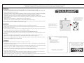
COLLEGAMENTO ELETTRICO
ELECTRICAL CONNECTIONS
BRANCHEMENTS ELECTRIQUES
ELEKTRISCHE ANSCHLÜSSE
CONEXIONES ELECTRICAS
RICAMBI / SPARE PARTS / DETACHEES / ERSATZEILE / RECAMBIOS
Scheda base
Motherboard
Carte base
Grundplatine
Tarjeta base ZBXE24
Documentazione
Tecnica
L51L51
L51L51
L51
rev. 1.01.0
1.01.0
1.0
©©
©©
© CAME 04/99
319L51
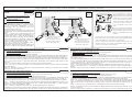
Alimentazione 230V (a.c.)
230V (a.c.) power input
Alimentation 230V (a.c.)
Stromversorgung 230V (Wechselstrom)
Alimentación 230V (a.c.)
Motore 24V(d.c.)
24V (d.c.) motor
Moteur 24V (c.c.)
Motor 24V (Gleichstrom)
Motor 24V (d.c.)
Uscita 24V (a.c.) in movimento (es.lampeggiatore)
24V (a.c.) output in motion (e.g. flashing light)
Sortie 24V (a.c.) en mouvement (ex. branchement clignotant)
Ausgang 24V (Wechselstrom) in Bewegung (z.B. Blinker-Anschluß)
Salida de 24V (a.c.) en movimento (p.ej. conexión lámpara intermitente)
Alimentazione accessori 24V (a.c.) max. 40W
24V (a.c.)Powering accessories (max 40W)
Alimentation accessoires 24V (a.c.) max.40W
Zubehörspeisung 24V (Wechselstrom) max. 40W
Alimentación accesoios 24V (a.c.) max. 40W
Pulsante stop (N.C.)
Pushbutton stop (N.C.)
Bouton-poussoir arrêt (N.F.)
Stop-Taste (N.C.)
Pulsador de stop (N.C.)
Pulsante apertura parziale (N.O.)
Pushbutton partial opening (N.O.)
Bouton-possoir ouverture partielle (N.O.)
Taste Tielöffnung (N.O.)
Pulsador de apertura parcial (N.O.)
Pulsante apre (N.O.)
Open button (N.O.)
Poussoir de ouverture (N.O.)
Taste Öffnen (Arbeitskontakt)
Pulsador de apertura (N.O.)
Pulsante chiude (N.O.)
Close button (N.O.)
Poussoir de fermeture (N.O.)
Taste Schließen (Arbeitskontakt)
Pulsador de cierre (N.O.)
Lampada spia (24V-3W) cancello aperto
(24V-3W) gate-opened signal lamp
Lampe-témoin (24V-3W) portail ouverture
Signallampe (24V-3W), Öffnen
Lampara indicadora (24V-3W) puerta abierta
Contatto radio e/o pulsante per comando (N.O.) "vedi dip-switch 7-8-9-10"
Contact radio and/or button for control (N.O.) see dip-switch 7-8-9-10"
Contact radio et/ou bouton-poussoir (N.O.)"voir dip-switch 7-8-9-10"
Funkkontakt und/oder Taste Steuerart (N.O.) "sehen dip-switch 7-8-9-10"
Contacto radio y/o pulsador para mando (N.O.) "mirar dip-switch 7-8-9-10"
Uscita per comando simultaneo di n.2 motori abbinati
Connection for simultaneous control of 2 combined motors
Sortie pour commande simultanée de 2 moteurs accouples
Ausgang zur gleichzeitigen Steuerung von 2 parallelgeschalteten
Salida para el mando simultáneo de n.2 motores acoplados
Contatto (N.C.) di «riapertura durante la chiusura»
Contact (N.C.) for «re-aperture during closure»
Contact (N.C.) de «réouverture pendant la fermeture»
Kontakt (Ruhekontakt) Wiederöffnen beim Schliessen
Contacto (N.C.) para la apertura en la fase de cierre
Contatto (N.C.) stop parziale
Partial stop contact (N.C.)
Contact (N.C.) d'arrêt partial
Teil-Stop (Ruhekontakt) Kontakt
Contacto (N.C.) de stop parcial
Uscita contatto (N.O.) Portata contatto: 5A a 24V (d.c.)
Contact output (N.O.) Resistive load: 5A 24V (d.c.)
Sortie contact (N.O.) Portée contact: 5A a 24V (c.c.)
Ausgang Arbeitskontakt Stromfestigkeit: 5A bei 24V (Gleichstrom)
Salida contacto (N.O.) Carga resistiva: 5A a 24V (d.c.)
Collegamento antenna
Antenna connection
Connexion antenne
Antennenanschluß
Conexión antena
10
E1
M
N
L1
L2
10
11
1
2
2
3P
2
C3
10
5
B1
B2
2
4
2 MOT
2
3
2
7
2
C1
10 11 E1 172534
3P 2C1
C3
2MOT B1 B2
M NL1 L2 ENCODER

DIP-SWITCH
12345678910
ON
OFF
SELEZIONI FUNZIONI - SELECTION OF FUNCTIONS - SÉLECTION FONCTIONS - FUNKTIONSWAHL- SELECCIÓN DE LAS FUNCIONES
1 ON Funzionamento "uomo presente" attivato
2 ON Funzionamento chiusura automatica attivata;
3 ON Funzionamento rilevazione ostacolo attivato;
4 ON Funzionamento prelampeggio attivato;
5 ON Funzionamento "spare" (programmazione finecorsa) attivato;
6 ON Funzionamento "master" attivato
7 ON Funzionamento "apre-chiude-inversione" con pulsante (2-7) attivato;
8 ON Funzionamento "apre-stop-chiude-stop" con pulsante (2-7) attivato;
7 ON - 9 ON Funzione "apre-chiude" con radiocomando attivato (scheda AF inserita)
8 ON - 9 ON Funzione "apre-stop-chiude-stop" con radiocomando attivato (scheda AF inserita)
7 ON - 10 ON Funzione "solo apertura" con radiocomando attivato (scheda AF inserita)
I
1 ON "Present man" operation enabled.
2 ON Automatic closure function enabled;
3 ON Obstacle detection device (motor of limit position) enabled;
4 ON "Pre-flashing" function enabled;
5 ON "Spare" (limit switch programming) enabled;
6 ON "Master" function enabled
7 ON "Open-close-reverse" function with button (2-7) enabled;
8 ON "Open-stop-close-stop" function with button (2-7) enabled;
7 ON - 9 ON "Open-close-reverse" function with radio control enabled, (AF board inserted)
8 ON - 9 ON "Open-stop-close-stop" function with radio control enabled, (AF board inserted)
7 ON - 10 ON "Only open" function with radio control enabled, (AF board inserted)
GB 1 ON Fonctionnement "contact mantenu" sélectionée
2 ON Fonctionnement fermeture automatique sélectionneé;
3 ON Dispositif de détection de présence (moteur en fin de course) sélectionneé;
4 ON Fonctionnement preclignotement sélectionneé;
5 ON Fonctionnement "spare" (programmation fin de course) sélectionneé;
6 ON Fonctionnement "master" sélectionée
7 ON Fonction "ouverture-fermeture" avec bouton (2-7) sélectionneé,
8 ON Fonction "ouverture-stop-fermeture-stop" avec bouton (2-7 sélectionneé;
7 ON - 9 ON Fonction "ouverture-fermeture" avec commande-radio sélectionneé, (carte AF insérée)
8 ON - 9 ON Fonction "ouverture-stop-fermeture-stop" avec commande-radio sél., (carte AF insérée)
7 ON - 10 ON Fonction "seulement ouverture" avec commande-radio sélectionneé, (carte AF insérée)
1 ON Bedienung vom "Steuerpult" zugeschaltet
2 ON Funksteuerung Schließautomatik zugeschaltet;
3 ON Funksteuerung Hindernisaufnahme zugeschaltet;
4 ON Funksteuerung Vorblinker zugeschaltet;
5 ON Funksteuerung "spare" (Programmierendausschalter) zugeschaltet;
6 ON Funksteuerung "master" zugeschaltet
7 ON Funksteuerung "Öffnen-Schließen" mit Druckknopf (2-7) zugeschaltet;
8 ON Funksteuerung "Öffnen-stop-Schließen-stop" mit Druckknopf (2-7) zugeschaltet;
7 ON - 9 ON Funktion "Öffnen-Schließen" mit Fernsteuerung zugeschaltet; (Karte AF eingesteckt)
8 ON - 9 ON Funktion "Öffnen-stop-Schließen-stop" mit Fernsteuerung zug.; (Karte AF eingesteckt)
7 ON - 10 ON Funktion "nur Öffnen" mit Fernsteuerung zugeschaltet; (Karte AF eingesteckt)
1 ON Funciónamiento "hombre presente" activado
2 ON Funciónamiento cierre automático activado;
3 ON Funciónamiento detección del obstàculo activado;
4 ON Funciónamiento preintermitencia activado;
5 ON Funciónamiento "spare" (programación final de carrera) activado;
6 ON Funciónamiento "master" activado;
7 ON Función "apertura-cierre" con botón (2-7) activado,
8 ON Función "apertura-stop-cierre-stop" con botón (2-7) activado;
7 ON - 9 ON Función "apertura-cierre" con radiocontrol activado, (tarjeta AF conectada)
8 ON - 9 ON Función "apertura-stop-cierre-stop" con radiocontrol activ., (tarjeta AF conectada)
7 ON - 10 ON Función "sólo apertura" con radiocontrol activado, (tarjeta AF conectada)
D
F
E

POUR UTILISER LA COMMANDE RADIO, IL FAUT:
A) Brancher une carte de radiofréquence AF,
B) Coder l'emetteur (*). Voir feuille d'instructions correspondante.
C) Mémoriser le code sur la carte de la manière suivante:
- En maintenant appuyée la touche "CH1" et aprés que le led de signalisation s'est allumé, envoyer une
commande avec la touche de l'émetteur: un bref clignotement du led signalera que la mémorisation a
été exécutée. (fig.1).
Suivre la même procédure avec la touche "CH2" en l'associant avec une autre touche du emetteur (fig.2).
CH1 = Canal pour obtenir la commande directe d'une fonction du boîtier du motoréducteur ( commande
"uniquement ouverture" / "ouverture-fermeture-inversion" ou "ouverte-stop-ferme-stop" en fonction de la
sélection effectuée sur les dip-switchs 7,8,9 et 10).
CH2 = Canal pour obtenir la commande directe d'un dispositif accessoire branché sur B1-B2.
N.B.: Si, successivement, on veut changer le code des émetteur, il suffit de répéter la séquence décrite ci-
dessus.
Attention: Couper la tension du tableau avant d'introduire ou d'extraire la carte de AF de la connexion.
TO USE THE REMOTE CONTROL SYSTEM, PROCEED AS FOLLOWS:
A) Insert an AF radiofrequency board,
B) Code the transmitter(*). See the relative instruction sheet.
C) Store the code on circuit card. Proceed as follows:
-While holding down key "CH1", press the control key on the transmitter after the signal LED lights up.
When the key is pressed, the LED will flash briefly to signal that the command has been stored (fig. 1).
Perform the same procedure with the "CH2" key, associating it with another transmitter key (figure 2).
CH1 = Channel for direct control of one function performed by the control unit on the gear motor ("open
only" / "open-close-reverse" or "open-stop-close-stop", depending on the position of dip switches 7,8,9
and 10).
CH2 = Channel for direct control of an accessory connected across B1-B2.
N.B. If you wish to change the code on your transmitters in the future, simply repeat the procedure
described above.
Warning: Disconnect power supply from control board before inserting or removing the AF radio-
frequency card from the socket.
VOR EINSATZ DER FUNKFERNSTEUERUNG IST:
A) Eine AF FunkFrequenze-Platine stecken,
B) Die Sender-Codierung durchzuführen (*).(siehe entsprechende Anleitung).
C) Dann die Codierung auf der Platine folgendermaßen speichern:
- Die Taste "CH1" gedrückt halten und nach Aufleuchten der Anzeige-Leuchtdiode über den Sender-Taster
einen Steuerimpuls ausführen: ein kurzes Blinken der Led zeigt die erfolgte Speicherung an (Abb.1).
Gehen Sie ebenso mit Taste "CH2" vor und ordnen sie ihr eine andere Taste des Senders zu (Abb.2)
CH1 = Kanal für die Direktsteuerung einer Funktion des Getriebemotor-Schaltkastens (Steuerung "nur
Öffnen" / "Öffnen-Schließen-Sicherheitsrücklauf" bzw. "Öffnen-Stp-Schließen-Stop", je nach über Dip-
Switch 7,8,9 und 10 ausgeführter Wahl).
CH2 = Kanal für Direktsteuerung eines über B1-B2 angeschlossenen Zubehörs.
HINWEIS: bei eventuell erwünschter Sender codeänderung ist der beschriebene Vorgang zu wiederholen.
Achtung! Schalten Sie unbedingt den Strom ab, bevor Sie die (AF) zum Einstecken oder herausnehmen.
PARA UTILIZAR EL MANDO A DISTANCIA ES PRECISO:
A) Introducir una tarjeta de radiofrecuencia AF,
B) Codificar el transmisor (*).Véase la correspondiente hoja instrucciones
C) Memorizar la codificación en la tarjeta de la siguiente manera:
- Manteniendo pulsada la tecla "CH1" y después del encendido del LED de señal con la tecla del transmisor:
una breve luz parpadeante del LED señalará que la memorización ha sido efectuada (fig.1).
Efectuar el mismo procedimiento con la tecla "CH2" asociándola a otra tecla del transmisor (fig.2).
CH1 = Canal para mando directo a una función de la central del motorreductor (mando "solo abre" /
"abre-cierra-inversión" o "abre-stop-cierra-stop", según la selección efectuada en los dip-switch 7,8,9 y
10).
CH2 = Canal para un mando directo a un dispositivo accesorio conectado en B1-B2.
NOTA: Si posteriormente se quisiera cambiar el código de los propios transmisores, sólo hay que repetir
la secuencia descrita.
Atención: Desconectar la tensión al cuadro antes de introducir o extraer la tarjeta de AF del racor.
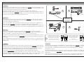
PER UTILIZZARE IL RADIOCOMANDO BI-
SOGNA:
A) Inserire una scheda di radiofrequenza
AF,
B) Codificare il trasmettitore(*). Vedi re-
lativo foglio istruzioni.
C) Memorizzare la codifica sulla sche-
da, nel seguente modo:
- Tenendo premuto il tasto "CH1" e dopo l'accen-
sione del led di segnalazione, inviare un coman-
do con il tasto del trasmettitore: un breve
lampeggio del led segnalerà l'avvenuta
memorizzazione (vedi fig.1).
Eseguire la stessa procedura con il tasto "CH2"
associandolo con un'altro tasto del trasmettitore
(fig.2).
CH1 = Canale per comandi diretti ad una
funzione della centralina del motoriduttore (co-
mando "solo apre" / "apre-chiude-inversione"
oppure "apre-stop-chiude-stop", a seconda del-
la selezione effetuata sui dip-switch 7,8,9 e 10).
CH2 = Canale per comandi diretti ad un dispo-
sitivo accessorio collegato su B1-B2.
N.B.: Se in seguito si vuol cambiare codice,
basta ripetere la sequenza descritta.
Attenzione: Togliere la tensione al quadro prima
di inserire o estrarre la scheda AF dall'innesto.
RADIOCOMANDO / RADIO CONTROL/ RADIOCOMMANDE / FUNKSTEUERUNG/ MANDO A DISTANCIA
(*) Per trasmettitori con frequenza
433.92 AM (serie TOP e serie TAM)
bisogna, sulla relativa scheda AF43S,
posizionare il jumper come illustrato
(*) On AM transmitters operating at
433.92 MHz (TOP and TAM series),
position the jumper connection on
circuit card AF43S as shown on the
sheet.
(*) Pour les émetteurs de fréquence
433.92 AM (série TOP et série TAM)
il faut positionner le pontet sur la carte
AF43S correspondante de la façon
indiquée.
TOP TAM
(*) Bei Sendern mit einer Frequenz von 433.92 AM (Reihe TOP und
Reihe TAM) ist der auf der entsprechenden Platine AF43S befindliche
Jumper der Abbildung entsprechend zu positionieren.
(*) Para transmisores con frecuencia 433.92 AM (serie TOP y serie
TAM) es necesario, en la tarjeta corespondiente AF43S, colocar el
jumper como se indica en la ilustración.
FRANÇAISFRANÇAIS
FRANÇAISFRANÇAIS
FRANÇAIS
DEUTSCHDEUTSCH
DEUTSCHDEUTSCH
DEUTSCH ESPAÑOLESPAÑOL
ESPAÑOLESPAÑOL
ESPAÑOL
ENGLISHENGLISH
ENGLISHENGLISH
ENGLISH
QUADRO CO M ANDO
BXE24
AF
ENCODER
CH1 CH2 F.APRE F.CHIUDE
PROGRAMMAZIONE
QUADRO CO M ANDO
BXE24
AF
ENCODER
CH1 CH2 F.APRE F.CHIUDE
PROGRAMMAZIONE
FIG.1
ABB.1 FIG.2
ABB.2
LED di segnalazione codice radio
Radio code signal LED
LED de signalisation code radio
Funkcode-Anzeigeleuchtdiode
LED de señal código radio
LED di segnalazione codice radio
Radio code signal LED
LED de signalisation code radio
Funkcode-Anzeigeleuchtdiode
LED de señal código radio
Scheda radiofrequenza AF
AF Radiofrequency board
Carte radiofrèquence AF
Funkfrequenze-Platine AF
Tarjeta radiofrecuencia AF
ITALIANOITALIANO
ITALIANOITALIANO
ITALIANO

PROGRAMMAZIONE FINECORSA / LIMIT SWITCH PROGRAMMING / PROGRAMMATION FIN DE COURSE ENDAUSSCHALTER-PROGRAMMIER / PROGRAMACIÓN FINAL DE CARRERA
montaggio a sinistra vista interna
mounting on the left-hand side of the gate
montage à gauche - vue de l'intérieur
die Montage auf der linken Seite
angeschlossen, interne Ansicht
montaje a la izquierda vista interior
eventuale montaggio a destra
if right-hand installation is desired
éventuel montage à droite
eventuelle Montage auf der
rechten Seite
eventual montaje a la derecha
MN
M
ENCODER
FINECORSA
MN
M
ENCODER
FINECORSA
5
CH1 CH2 F.APRE F.CHIUDE
PROGRAMMAZIONE
2
1345678910
ON
CH1 CH2 F.APRE F.CHIUDE
PROGRAMMAZIONE
2
1345678910
ON
4
3
1
APRE
LED di segnalazione
Signal LED
LED de signalisation
Anzeige-LED
LED de señal
Chiudere lo sportello dello sblocco e inserire il dip-switch 5 in ON, il led di segnalazione inizia
a lampeggiare (1). Portare il cancello in finecorsa chiude, premere il tasto "CHIUDE", il led
rimane acceso finchè si mantiene premuto il tasto (2).
Procedere portando il cancello a finecorsa apre e premere il tasto "APRE" (3).
Riposizionare il Dip-switch 5 in OFF (4), aprire lo sportello e inserire la manopola di sblocco.
N.B. In fase di programmazione finecorsa apre, se premendo il tasto "APRE" il led rimane spento,
invertire le fasi del motore ed Encoder come illustrato (5).
Close the door panel of the outlet and set dip-switch 5 to ON. The LED will begin flashing
(1). Bring the gate to the close limit-switch, press button CHIUDE; the LED will remain lit
as long as the button is released (2).
Now, move the gate to the end-of-travel position when open, and press the "APRE" key (3).
Move Dip-switch 5 to OFF (4), open the access door and turn the release Knob.
N.B. If the LED does not light up when the "APRE" key is pressed to program the end-of-travel
position when opened, reverse the motor and encoder connections as shown on the diagram (5).
Fermer le volet de déblocage et insérer le dip-switch 5 sur ON, le del de signalisation
commence à clignoter (1). Mettre le grille sur la butée de fin de course ferme, appuyer sur la
touche CHIUDE, le led reste allumé tant que lon appuie sur la touche (2).
Procéder en amenantle portail en position de fin de course ouverture puis appuyer sur la touche
"APRE" (3). Déconnecter le Dip-switch 5 sur OFF (4), ouvrir la porte et insérer la poignée de
déblocage.
N.B. Pendant la phase de programmation de la fin de course ouverture, si, en appuyant sur la
touche "APRE", le led reste éteint, inverser les phases du moteur et de l'encodeur de la façon
indiquée (5).
Schließen Sie das Freigabetürchen und schalten Sie den Dip-Switch 5 auf ON. Jetzt beginnt die
Kontrolleuchte zu blinken (1). Das Tor bis zum Endanschlag Schließen bringen. Dazu die Taste
"CHIUDE" drücken. Das LED bleibt so lange an, wie die Taste gedrückt gehalten wird (2).
Das Tor ganz Öffnen (Öffnungsendstellung) und die Taste "APRE" drücken (3).
Dip-Switch 5 ausschalten (4), Abdeckung öffnen und Entriegelungsgriff einfügen.
HINWEIS: wenn die Anzeige-LED wõhrend des Drückens der Taste "APRE" in der
Öffnungsendschalter-Programmierphase erloschenbleibt, dann sind die Anschlüsse der
Motorphasendrõhte und des Encoders der Abbildung entsprechend zu wechseln (5).
ITALIANO
ENGLISH
FRANÇAIS
DEUTSCH ESPANIOL
Cierre la tapa del dispositivo de desbloqueo y conecte el dip-switch 5 en ON; el indicador
luminoso inicia a parpadear (1). Lleve la verja hasta el final de carrera de cierre, pulsar la
tecla CHIUDE; el indicador luminoso permanece encendido mientras se mantenga
apretado la tecla (2).
Proceder llevando la puerta a la posición final de carrera abre, pulsar la tecla "APRE" (3).
Desconetar el Dip-switch 5 en OFF (4), abrir la portezuela e introducir la manópola de
desbloqueo.
NOTA. En la fase de programación final de carrera abre, si pulsando la tecla "APRE" el LED
está apagado, invertir las fases del motor y Encoder como indicado en la figura (5).
CH1 CH2 F.APRE F.CHIUDE
PROGRAMMAZIONE
2
CHIUDE

A
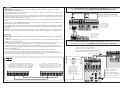
COLLEGAMENTO PER 2 MOTORI ABBINATI - CONNECTIONS FOR 2 COMBINED MOTORS - CONNEXIONS POUR 2 MOTEURS
ACCOUPLÉS - ANSCHLUSSE FÜR 2 PARALLELGESCHALTETEN MOTOREN - CONEXIÓN PARA 2 MOTORES ACOPLADOS
B
ITALIANO
ENGLISH
FRANÇAIS
AF
ENCO DER
1
2
REGOLAZIONI - SETTING - RÉGLAGES
EINSTELLUNGEN - REGULACIONES
FUNZIONI - FUNCTIONS- FONCTIONS
FUNKTIONEN - FUNCIONES
SCHEDA BASE DEL MOTORE "A"
"A" MOTOR MAIN BOARD
CARTE DE BASE DU MOTEUR "A"
BASISKARTE VOM MOTOR "A"
TARJETA BASE DEL MOTOR «A»
SCHEDA RADIOFREQUENZA "AF"
"AF" RADIO FREQUENCY BOARD
CARTE FREQUENCE RADIO "AF"
RADIOFREQUENZKARTE «AF»
TARJETA RADIOFRECUENCIA
SCHEDA BASE DEL MOTORE "A"
"A" MOTOR MAIN BOARD
CARTE DE BASE DU MOTEUR "A"
BASISKARTE VOM MOTOR "A"
TARJETA BASE DEL MOTOR «A»
Nel caso di installazione di due motori abbinati, procedere nel seguente modo:
- Coordinare il senso di marcia dei motoriduttori "A" e "B", modificando la rotazione del motore "B"
(vedi programmazione finecorsa);
- Stabilire tra A e B il motore master (o pilota), posizionare il dip 6 in ON sul selettore funzioni della
scheda base (1). Per "master" s'intende il motore che comanda ambedue i cancelli;
- Assicurarsi che sia inserito il ricevitore radio (AF) sul quadro del motore "master" (2);
- Eseguire solo sulla morsettiera master i collegamenti elettrici e selezionare le funzioni predisposte
normalmente (3);
- Eseguire tra le morsettiere i collegamenti come da "Figura A"
- Assicurarsi che i dip del quadro del 2° motore siano disattivati (OFF) 4.
NOTA: Se i due cancelli abbinati sono di dimensioni diverse, la funzione master deve essere inserita
nel quadro del motore installato sull'anta più lunga.
In case two combined motors are installed, proceed in the following manner:
- Match the directions in which gear motors A and B rotate by changing the direction in which motor
B rotates (see limit switch);
- Set the master (or pilot) motor between A and B by setting dip-switch 6 to ON on the control board
(1). "Master" refers to the motor that controls both the gates.
- Check that the (AF) radio receiver is activated only on the MASTER board (2);
- Make the electrical connections and the normally used selections only on the MASTER terminal
board (3);
- Wire the electrical connections between the terminal boards, as shown in the "Figure A";
- Make sure that all the dip-switches on the board of the 2nd motor are (OFF)4.
NB: If the two coupled gates are of different sizes, the master function must be fitted to the motor
control board installed on the longer door.
Pour installer deux moteurs accouplés, procéder comme suit:
- Coordonnerle le sens de marche des motoreducteurs A et B en modifiantle sens de rotation du
moteur B (voir fin de course);
- Fixer entre A et B le moteur master (ou pilote) en positionnant le dip-switch 6 sur ON sur la carte
commande (1). Par "master" il s'agit du moteur qui commande les deux grilles.
- S'assurer que le récepteur radio (AF) est inséré sur le cadre MASTER (2);
- Effecteur seulement sur la barrette de connexion MASTER les liaisons électriques et les sélections
normalment prédisposées (3);
- Effectuer les branchements entre les plaques à bornes de la façon indiquée sur la "Figure A";
- S'assurer que tous les dip du pupitre du 2sd moteur sont èteints OFF (4).
NOTE: Si les deux grilles accouplées ont une dimension différente, la fonction maîtresse doit être
prévue dans le tableau du moteur installé sur la porte la plus longue.
3
2
1345678910
O
N
SETTAGGIO OBBLIGATORIO
OBLIGATORY SETTING
INSTALLATION OBLIGATOIRE
DAS SETUP IST OBLIGATORISCH
REGULACION OBLIGATORIA

ABCD
R2
R1
L
I
H
G
F
E
D
+24
+12
-
A
B
C
MICROINTERRUTTORE SPORTELLO
THE MOTOR DOOR'S SAFETY MICROSWITCH
MICROCONTACT DE LA PORTE DU MOTEUR
SICHERUNGSMIKROSCHALTER DER MOTORENKLAPPE
MICROINTERRUPTOR DE DESBLOQUEO DEL MOTOR
+
_
+
_
TAGLIARE IL DIODO INDICATO
CUT DIODE INDICATED
COUPER LA DIODE INDIQUÉE
GEKENNZEICHNETE DIODE ABTRENNEN
ELIMINAR EL DIODO INDICADO
ESPANIOL
DEUTSCH
Wenn zwei kombinierte Motoren installiert werden sollen, gehen Sie dazu
bitte folgendermaßen vor:
- Die Gangrichtung der Getriebemotoren A und B durch Drehrichtungsõnderung des Motores
B (siehe Endschalter) koordinieren;
-Legen Sie fest, welcher der Motoren A und B der Master-Motor (übergeordnet) sein soll. Stellen
Sie dazu den Dip-Switch 6 auf der Steuerungskarte auf ON (1). Unter Master-Motor wird der
Motor verstanden, der beide Tore steuert.
- Versichern Sie sich, daß der Radioempfänger (AF) nur auf der MASTER Schalttafel angebracht
ist (2);
- Führen Sie nur am MASTER Klemmbrett die elektrischen Anschlüsse und die normalerweise
durchgeführten Voreinstellungen aus (3);
- Die Verbindungen zwischen den beiden Klemmleisten der Abbildung entsprechend ausführen;
- Kontrollieren Sie, daß alle Dip-Switch auf der Schalttafel des untergeordneten Motor auf OFF
stehen (4).
HINWEIS: Wenn die beiden gekoppelten Tore unterschiedlich graß sind, muß die Master-
Funktion in die Schalttafel der Motors eingesetzt werden, der am längeren Tor installiert ist.
En el caso de instalación de dos motores combinados, actúe de la siguiente
manera:
- Coordinar el sentido de marcha de los motorreductores A y B, modificando la rotación del
motor B (ver final de carrera);
- Establezca el motor master (o piloto) entre los motores A y B, colocando el dip-switch 6 en ON
en la tarjeta de mando (1). "Master" significa que el motor acciona ambas puertas.
- Asegúrese de que el radiorreceptor (AF) estè conectado sólo en el cuadro MASTER (2);
- Realice las conexiones eléctricas y las selecciones normalmente reguladas, sólo en el tablero
de bornes MASTER (3);
- Efectuar entre las cajas de bornes las conexions como indicado en la "Figura A";
- Asegúrese de que todos los dip del cuadro del 2° motor estén desactivados OFF (4).
NOTA: Si las dos verjas asociadas tienen distintos tamaño, la función master se tiene que
conectar en el cuadro del motor instalado en la hoja más larga.
«Fig. A»«Fig. A»
«Fig. A»«Fig. A»
«Fig. A»
«Abb.A»«Abb.A»
«Abb.A»«Abb.A»
«Abb.A»
Morsettiera del quadro motore «MASTER»
Terminal board of the "MASTER" motor control panel
Plaque à bornes du tableau du moteur «MASTER»
Klemmbrett der Schalttafel vom Motor «MASTER»
Tablero de bornes del cuadro motor «MASTER»
Morsettiera del quadro motore «2»
Terminal board of the "2" motor control panel
Plaque à bornes du tableau du moteur «2»
Klemmbrett der Schalttafel vom Motor «2»
Tablero de bornes del cuadro motor «2»
10 11 E1 1725343P 2C1
C3 10 11 E1 1725343P 2C1
C3
2MOT
2MOT
COLLEGAMENTO CON CARICA BATTERIE LB18 /
CONNECTION WITH LB18 BATTERY
CHARGER /
BRANCHEMENT AVEC CHARGEUR DE BATTERIES LB18
/
ANSCHLUSS MIT
BATTERIELADEGERÄT LB18
/ CONEXIÓN CON CARGADOR DE BATERÍA LB18
BATTERIE DI EMERGENZA
(12V-1,2Ah) ESCLUSE
STANDBY BATTERY (12V-
1,2Ah, NOT INCLUDED)
BATTERIES D'URGENCE
(12V-1,2Ah) EXCLUES
NOTBATTERIEN (12V-1,2Ah)
AUSGESCHLOSSEN
BATERIAS DE EMERGENCIA
(12V-1,2Ah) EXCLUIDAS
COLLEGAMENTO CON CARICA BATTERIE BN1/
CONNECTION WITH BN1 BATTERY
CHARGER /
BRANCHEMENT AVEC CHARGEUR DE BATTERIES BN1/
ANSCHLUSS MIT
BATTERIELADEGERÄT BN1
/ CONEXIÓN CON CARGADOR DE BATERÍA BN1
BATTERIA
-
- -
ABC
D
ABCD
SCHEDA BASE BXN1
BXN1 MOTHERBOARD
CARTE DE BASE BXN1
BASISKARTE BXN1
TARJETA BASE BXN1
SCHEDA BASE ZBXE24
ZBXE24 MOTHERBOARD
CARTE DE BASE ZBXE24
BASISKARTE ZBXE24
TARJETA BASE ZBXE24
BATTERIE DI EMERGENZA (12V-1,2Ah) ESCLUSE
STANDBY BATTERY (12V-1,2Ah, NOT INCLUDED)
BATTERIES D'URGENCE (12V-1,2Ah) EXCLUES
NOTBATTERIEN (12V-1,2Ah) AUSGESCHLOSSEN
BATERIAS DE EMERGENCIA (12V-1,2Ah) EXCLUIDAS
-
 1
1
-
 2
2
-
 3
3
-
 4
4
-
 5
5
-
 6
6


in anderen Sprachen
- English: CAME BX, ZBXE24
- français: CAME BX, ZBXE24
- español: CAME BX, ZBXE24
- italiano: CAME BX, ZBXE24
Verwandte Papiere
-
CAME BX Series Benutzerhandbuch
-
-
CAME BZ Bedienungsanleitung
-
-
-
-
-
CAME ZBKS Benutzerhandbuch
-
-