
POG 90 + FSL
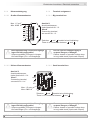
Kombination
Inkrementaler Drehgeber mit integriertem
Fliehkraftschalter
Combination
Incremental encoder with integrated
centrifugal switch
Montage- und Betriebsanleitung
Mounting and operating instructions
MB154.1 - 11064671
Baumer_POG90-FSL_II_DE-EN (19A3)

Baumer_POG90-FSL_II_DE-EN (19A3)
MB154.1 - 11064671
Inhaltsverzeichnis
Inhaltsverzeichnis
1 Allgemeine Hinweise ..........................................................................................................................................................1
2 Sicherheitshinweise
........................................................................................................................................................... 3
3 Vorbereitung
............................................................................................................................................................................ 5
3.1 Lieferumfang
............................................................................................................................................................... 5
3.2 Zur Montage erforderlich (nicht im Lieferumfang enthalten)
............................................................. 6
3.3 Erforderliches Werkzeug (nicht im Lieferumfang enthalten)
............................................................. 6
4 Montage
....................................................................................................................................................................................... 7
4.1 Schritt 1
......................................................................................................................................................................... 7
4.2 Schritt 2
......................................................................................................................................................................... 7
4.3 Schritt 3
......................................................................................................................................................................... 8
4.4 Schritt 4
......................................................................................................................................................................... 8
4.5 Maximal zulässige Montagefehler unter Verwendung der
Baumer Hübner Federscheibenkupplung K 35
........................................................................................ 9
5.6 Hinweis bei Verwendung einer Klauenkupplung (zum Beispiel „ROTEX®“)
..........................10
4.6 Montagehinweis
......................................................................................................................................................11
5 Abmessungen
.......................................................................................................................................................................12
5.1 Großer Klemmenkasten
......................................................................................................................................12
5.1 Kleiner Klemmenkasten
......................................................................................................................................12
6 Elektrischer Anschluss
..................................................................................................................................................13
6.1 POG 90
........................................................................................................................................................................13
6.1.1 Kabelanschluss
....................................................................................................................................................13
6.1.1.1 Großer Klemmenkasten - Schritt 1 bis 3
...................................................................................13
6.1.1.2 Großer Klemmenkasten - Schritt 4 und 5
.................................................................................14
6.1.1.3 Großer Klemmenkasten - Schritt 6
..............................................................................................15
6.1.1.4 Kleiner Klemmenkasten - Schritt 1 und 2
.................................................................................16
6.1.2 Beschreibung der Anschlüsse
.....................................................................................................................17
6.1.3 Ausgangssignale
.................................................................................................................................................17
6.1.4 Klemmenbelegung
.............................................................................................................................................18
6.1.4.1 Großer Klemmenkasten
.....................................................................................................................18
6.1.4.2 Kleiner Klemmenkasten
.....................................................................................................................18
6.1.5 Sensorkabel HEK 8 (Zubehör)
.....................................................................................................................19
6.2 FSL
................................................................................................................................................................................ 20
6.2.1 Kabelanschluss
................................................................................................................................................... 20
6.2.2 Klemmenbelegung
.............................................................................................................................................21
7 Demontage
............................................................................................................................................................................. 22
7.1 Schritt 1
...................................................................................................................................................................... 22
7.2 Schritt 2
...................................................................................................................................................................... 22
7.3 Schritt 3
...................................................................................................................................................................... 22
8 Technische Daten
.............................................................................................................................................................. 23
8.1 Technische Daten - elektrisch
........................................................................................................................ 23
8.2 Technische Daten - elektrisch (Drehgeber)
............................................................................................. 23
8.3 Technische Daten - elektrisch (Fliehkraftschalter)
.............................................................................. 23
8.4 Technische Daten - mechanisch
................................................................................................................... 24
9 Zubehör
.................................................................................................................................................................................... 27

MB154.1 - 11064671
Baumer_POG90-FSL_II_DE-EN (19A3)
Table of contents
Table of contents
1 General notes .......................................................................................................................................................................... 2
2 Security indications
............................................................................................................................................................ 4
3 Preparation
............................................................................................................................................................................... 5
3.1 Scope of delivery
...................................................................................................................................................... 5
3.2 Required for mounting (not included in scope of delivery)
................................................................. 6
3.3 Required tools (not included in scope of delivery)
.................................................................................. 6
4 Mounting
..................................................................................................................................................................................... 7
4.1 Step 1
............................................................................................................................................................................. 7
4.2 Step 2
............................................................................................................................................................................. 7
4.3 Step 3
............................................................................................................................................................................. 8
4.4 Step 4
............................................................................................................................................................................. 8
4.5 Maximum permissible mounting tolerance when the
Baumer Hübner K 35 spring disk coupling is used
................................................................................. 9
5.6 Note when using a jaw-type coupling (for example “ROTEX®”)
...................................................10
4.6 Mounting instruction
.............................................................................................................................................11
5 Dimensions
.............................................................................................................................................................................12
5.1 Big terminal box
......................................................................................................................................................12
5.1 Small terminal box
.................................................................................................................................................12
6 Electrical connection
.......................................................................................................................................................13
6.1 POG 90
........................................................................................................................................................................13
6.1.1 Cable connection
................................................................................................................................................13
6.1.1.1 Big terminal box - Step 1 up to 3
...................................................................................................13
6.1.1.2 Big terminal box - Step 4 and 5
......................................................................................................14
6.1.1.3 Big terminal box - Step 6
...................................................................................................................15
6.1.1.4 Small terminal box - Step 1 and 2
.................................................................................................16
6.1.2 Terminalsignicance
........................................................................................................................................17
6.1.3 Output signals
.......................................................................................................................................................17
6.1.4 Terminal assignment
.........................................................................................................................................18
6.1.4.1 Big terminal box
.....................................................................................................................................18
6.1.4.2 Small terminal box
................................................................................................................................18
6.1.5 Sensor cable HEK 8 (accessory)
................................................................................................................19
6.2 FSL
................................................................................................................................................................................ 20
6.2.1 Cable connection
............................................................................................................................................... 20
6.2.2 Terminal assignment
.........................................................................................................................................21
7 Dismounting
.......................................................................................................................................................................... 22
7.1 Step 1
.......................................................................................................................................................................... 22
7.2 Step 2
.......................................................................................................................................................................... 22
7.3 Step 3
.......................................................................................................................................................................... 22
8 Technical data
...................................................................................................................................................................... 25
8.1 Technical data - electrical ratings
................................................................................................................. 25
8.2 Technical data - electrical ratings (encoder)
........................................................................................... 25
8.3 Technical data - electrical ratings (centrifugal switch)
....................................................................... 25
8.4 Technical data - mechanical design
............................................................................................................ 26
9 Accessories
........................................................................................................................................................................... 27

1
Baumer_POG90-FSL_II_DE-EN (19A3)
MB154.1 - 11064671
1 Allgemeine Hinweise
1 Allgemeine Hinweise
1.1 Zeichenerklärung:
Gefahr
Warnung bei möglichen Gefahren
Hinweis zur Beachtung
Hinweis zur Gewährleistung eines einwandfreien Betriebes des Gerätes
i
Information
Empfehlung für die Gerätehandhabung
1.2 Die Kombination POG 90 + FSL ist ein opto-elektronisches Prä zi sionsmessgerät und ein
mechanisch wirkendes Schaltgerät, das mit Sorgfalt nur von technisch qualiziertem Per
sonal gehandhabt werden darf.
1.3 Die konstruktive Auslegung des Fliehkraftschalters ist die Verwendung als Schalter mit Zwangs-
öffnerfunktion. Er darf nicht als Dauerschalter (Schaltzyklen größer 500 während der
Lebensdauer) verwendet werden.
1.4 Die zu erwartende Lebensdauer des Gerätes hängt von den Kugellagern ab, die mit einer
Dauerschmierung ausgestattet sind.
1.5
Der Lagertemperaturbereich des Gerätes liegt zwischen -15 °C bis +70 °C.
1.6
Der Betriebstemperaturbereich des Gerätes liegt zwischen -20 °C bis +85 °C,
am Gehäuse gemessen.
1.7
EU-Konformitätserklärung gemäß den europäischen Richtlinien.
1.8 Wir gewähren 2 Jahre Gewährleistung im Rahmen der Bedingungen des Zentralverbandes der
Elektroindustrie (ZVEI).
1.9 Wartungsarbeiten sind nicht erforderlich. Das Gerät darf nur wie in dieser Anleitung beschrie-
ben geöffnet werden. Reparaturen, die ein vollständiges Öffnen des Gerätes erfordern, sind
ausschließlich vom Hersteller durchzuführen. Am Gerät dürfen keine Veränderungen vorge-
nommen werden.
1.10 Bei Rückfragen bzw. Nachlieferungen sind die auf dem Typenschild des Gerätes angege-
benen Daten, insbesondere Typ und Seriennummer, unbedingt anzugeben.
1.11
Entsorgung (Umweltschutz):
Gebrauchte Elektro- und Elektronikgeräte dürfen nicht im Hausmüll entsorgt werden.
Das Produkt enthält wertvolle Rohstoffe, die recycelt werden können. Wenn immer
möglich sollen Altgeräte lokal am entsprechenden Sammeldepot entsorgt werden. Im
Bedarfsfall gibt Baumer den Kunden die Möglichkeit, Baumer-Produkte fachgerecht zu entsor-
gen. Weitere Informationen siehe www.baumer.com.
i
Achtung!
Beschädigung des auf dem Gerät bendlichen Siegels führt zu Gewährleistungsver-
lust.

MB154.1 - 11064671
Baumer_POG90-FSL_II_DE-EN (19A3)
2
General notes 1
1 General notes
1.1 Symbol guide:
Danger
Warnings of possible danger
General information for attention
Informations to ensure correct device operation
i
Information
Recommendation for device handling
1.2 The combination POG 90 + FSL is an opto electro nic precision measurement device and a
mechanically operated switching device which must be handled with care by skilled person-
nel only.
1.3 The constructive design of the centrifugal switch is its use as a switch with positive break func-
tion. It must not be used as a continuous switch (switching cycles greater than 500 during
service life).
1.4 The expected service life of the device depends on the ball bearings, which are equipped with
a permanent lubrication.
1.5
The storage temperature range of the device is between -15 °C and +70 °C.
1.6
The operating temperature range of the device is between -20 °C and +85 °C,
measured at the housing.
1.7
EU Declaration of Conformity meeting to the European Directives.
1.8 We grant a 2-year warranty in accordance with the regulations of the ZVEI (Central Association
of the German Electrical Industry).
1.9 Maintenance work is not necessary. The device may be only opened as described in this
instruction. Repair work that requires opening the device completely must be carried out by the
manufacturer. Alterations of the device are not permitted.
1.10 In the event of queries or subsequent deliveries, the data on the device type label must be
quoted, especially the type designation and the serial number.
1.11
Disposal (environmental protection):
Do not dispose of electrical and electronic equipment in household waste. The product
contains valuable raw materials for recycling. Whenever possible, waste electrical and
electronic equipment should be disposed locally at the authorized collection point. If
necessary, Baumer gives customers the opportunity to dispose of Baumer products profession-
ally. For further information see www.baumer.com.
i
Warning!
Damaging the seal on the device invalidates warranty.

3
Baumer_POG90-FSL_II_DE-EN (19A3)
MB154.1 - 11064671
2 Sicherheitshinweise
2 Sicherheitshinweise
2.1 Verletzungsgefahr durch rotierende Wellen
Haare und Kleidungsstücke können von rotierenden Wellen erfasst werden.
• Vor allen Arbeiten alle Betriebsspannungen ausschalten und Maschinen stillsetzen.
2.2 Zerstörungsgefahr durch elektrostatische Auadung
Die elektronischen Bauteile im Gerät sind empndlich gegen hohe Spannungen.
• Steckkontakte und elektronische Komponenten nicht berühren.
• Ausgangsklemmen vor Fremdspannungen schützen.
• Maximale Betriebsspannung nicht überschreiten.
2.3 Zerstörungsgefahr durch mechanische Überlastung
Eine starre Befestigung kann zu Überlastung durch Zwangskräfte führen.
• Die Beweglichkeit des Gerätes niemals einschränken.
Unbedingt die Montagehinweise beachten.
• Die vorgegebenen Abstände und/oder Winkel unbedingt einhalten.
2.4 Zerstörungsgefahr durch mechanischen Schock
Starke Erschütterungen, z. B. Hammerschläge, können zur Zerstörung der Abtastung führen.
• Niemals Gewalt anwenden.
Bei sachgemäßer Montage lässt sich alles leichtgängig zusammenfügen.
• Für die Demontage geeignetes Abziehwerkzeug benutzen.
2.5 Zerstörungsgefahr durch Verschmutzung
Schmutz kann im Gerät zu Kurzschlüssen und zur Beschädigung der Abtastung führen.
• Während aller Arbeiten am Gerät auf absolute Sauberkeit achten.
• Niemals Öl oder Fett in das Innere des Gerätes gelangen lassen.
2.6 Zerstörungsgefahr durch klebende Flüssigkeiten
Klebende Flüssigkeiten können die Abtastung und die Kugellager beschädigen. Die Demontage
eines mit der Achse verklebten Gerätes kann zu dessen Zerstörung führen.
2.7 Explosionsgefahr
Das Gerät nicht in Bereichen mit explosionsgefährdeten bzw. leicht entzündlichen Materialien
verwenden. Durch eventuelle Funkenbildung können diese leicht Feuer fangen und/oder explo-
dieren.

MB154.1 - 11064671
Baumer_POG90-FSL_II_DE-EN (19A3)
4
Security indications 2
2 Security indications
2.1 Risk of injury due to rotating shafts
Hair and clothes may become tangled in rotating shafts.
• Before all work switch off all voltage supplies and ensure machinery is stationary.
2.2 Risk of destruction due to electrostatic charge
Electronic parts contained in the device are sensitive to high voltages.
• Do not touch plug contacts or electronic components.
• Protect output terminals against external voltages.
• Do not exceed maximum voltage supply.
2.3 Risk of destruction due to mechanical overload
Rigid mounting may give rise to constraining forces.
• Never restrict the freedom of movement of the device.
The mounting instructions must be followed.
• Itisessentialthatthespeciedclearancesand/oranglesareobserved.
2.4 Risk of destruction due to mechanical shock
Violent shocks, e. g. due to hammer impacts, can lead to the destruction of the sensing system.
• Never use force.
Mounting is simple when correct procedure is followed.
• Use suitable puller for dismounting.
2.5 Risk of destruction due to contamination
Dirt penetrating inside the device can cause short circuits and damage the sensing system.
• Absolute cleanliness must be maintained when carrying out any work on the device.
• Never allow lubricants to penetrate the device.
2.6 Risk of destruction due to adhesive uids
Adhesiveuidscandamagethesensingsystemandtheballbearings.Dismountingadevice,
secured to a shaft by adhesive may lead to the destruction of the device.
2.7 Explosion risk
Donotusethedeviceinareaswithexplosiveand/orhighlyinfammablematerials.Theymay
explodeand/orcatchfrebypossiblesparkformation.

5
Baumer_POG90-FSL_II_DE-EN (19A3)
MB154.1 - 11064671
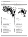
3 Vorbereitung/Preparation
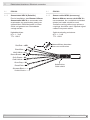
1
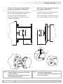
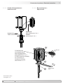
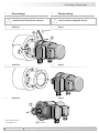
Gehäuse POG 90
2
Gehäuse FSL
3
Vollwelle mit Passfeder
4
EURO-Flansch B10
5
1)
Klemmenkastendeckel POG 90
6
1)
Torx-/Schlitzschraube M4x32 mm
7
1)
Kabelverschraubung M20x1,5 mm
für Kabel ø5...13 mm
8
1)
Anschlussplatine POG 90,
siehe Abschnitt 6.1.1.2 und 6.1.4.1.
9
1)
Torx-/Schlitzschraube M3x10 mm
10
1)
D-SUB Stecker
am Gerätegehäuse
11
1)
Anschlussklemmen POG 90,
siehe Abschnitt 6.1.1.4 und 6.1.4.2.
12
Klemmenkastendeckel FSL
13
Torx-/Schlitzschraube M4x32 mm
14
Kabelverschraubung M20x1,5 mm
für Kabel ø5...13 mm
15
Anschlussklemmen FSL,
siehe Abschnitt 6.2.
1)
Je nach Version
1
Housing POG 90
2
Housing FSL
3
Solid shaft with key
4
EUROangeB10
5
1)
Terminal box cover POG 90
6
1)
Torx/slottedscrewM4x32mm
7
1)
Cable gland M20x1.5 mm
for cable ø5...13 mm
8
1)
Connecting board POG 90,
see section 6.1.1.2 and 6.1.4.1.
9
1)
Torx/slottedscrewM3x10mm
10
1)
D-SUB connector (male)
on the device housing
11
1)
Connecting terminal POG 90,
see section 6.1.1.4 and 6.1.4.2.
12
Terminal box cover FSL
13
Torx/slottedscrewM4x32mm
14
Cable gland M20x1.5 mm
for cable ø5...13 mm
15
Connecting terminal FSL,
see section 6.2.
1)
Depending on version
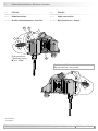
3 Vorbereitung
3.1 Lieferumfang
3 Preparation
3.1 Scope of delivery
14
9
8
11
13
12
7
6
5
14
4
3
2
1
1
10
Mit kleinem Klemmenkasten
With small terminal box
7
6
5
1) 1)
1)
1)
1)
1)
1)
1)
1)
1)

MB154.1 - 11064671
Baumer_POG90-FSL_II_DE-EN (19A3)
6
Vorbereitung/Preparation 3
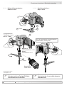
3.2 Zur Montage erforderlich
(nicht im Lieferumfang enthalten)
3.2 Required for mounting
(not included in scope of delivery)
16
Anbauvorrichtung, kundenspezisch
17
Befestigungsschrauben M6x16 mm für An-
bauvorrichtung, ISO 4017
18
Federscheibenkupplung K 35,
als Zubehör erhältlich, siehe Abschnitt 4.5.
19
Sensorkabel HEK 8, als Zubehör erhältlich,
siehe Abschnitt 6.1.5.
20
Anschlusskabel für FSL
16
Installationtting,customized
17
FixingscrewsM6x16mmforinstallationt-
ting, ISO 4017
18
Spring disk coupling K 35,
available as accessory, see section 4.5.
19
Sensor cable HEK 8, available as accessory,
see section 6.1.5.
20
Connecting cable for FSL
12x
16
17
18
19 20
3.3 Erforderliches Werkzeug
(nicht im Lieferumfang enthalten)
3.3 Required tools
(not included in scope of delivery)
2,5 mm
10 und 22 mm
TX 20
21
Werkzeugset als Zubehör erhältlich:
Bestellnummer 11068265
2.5 mm
10 and 22 mm
TX 20
21
Tool kit available as accessory:
Order number 11068265

4 Montage / Mounting
7
Baumer_POG90-FSL_II_DE-EN (19A3)
MB154.1 - 11064671
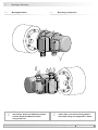
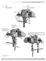
4.2 Schritt 2 4.2 Step 2
Antriebswelle einfetten. Lubricate drive shaft.
Die Antriebswelle sollte einen
möglichst kleinen Rundlauffehler
aufweisen, da dieser zu einem
Winkelfehler führen kann. Rundlauf-
fehler verursachen Vibrationen, die die
Lebensdauer des Gerätes verkürzen
können.
The drive shaft should have as less
runout as possible because this can
otherwise result in an angle error.
Runouts can cause vibrations, which
can shorten the service life of the
device.
4 Montage
4.1 Schritt 1
4 Mounting
4.1 Step 1
* Siehe Seite 6
See page 6
Anzugsmoment:
Tightening torque:
M
t
= 1 Nm
18
*
17
16
**
2.5 mm
10 mm

Montage / Mounting 4
MB154.1 - 11064671
Baumer_POG90-FSL_II_DE-EN (19A3)
8
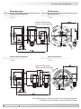
4.3 Schritt 3
4.4 Schritt 4
4.3 Step 3
4.4 Step 4
* Siehe Seite 6
See page 6
Anzugsmoment:
Tightening torque:
M
t
= 1.3 ±10 % Nm
17416
***
17
*
2.5 mm
10 mm

4 Montage / Mounting
9
Baumer_POG90-FSL_II_DE-EN (19A3)
MB154.1 - 11064671
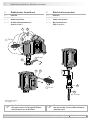
F
max
= 10N
4.5 Maximal zulässige Montagefehler
unter Verwendung der Baumer Hübner
Federscheibenkupplung K 35
Geräte mit Vollwelle sollten unter Verwen-
dung der Baumer Hübner Federschei-
benkupplung K 35 (Zubehör) angetrieben
werden, die sich ohne axialen Druck auf
die Welle schieben lässt.
4.5 Maximum permissible mounting toler-
ance when the Baumer Hübner K 35
spring disk coupling is used
Devices with a solid shaft should be
driven through the Baumer Hübner K 35
spring disk coupling (accessory), that can
be pushed onto the shaft without axial
loading.
Zulässiger Parallelversatz
Admissible parallel misalignment
Zulässiger Winkelfehler
Admissible angular error
Zulässige Axialbewegung
Admissible axial movement
±0.2 (±0.05*)
±1°
* Mit isolierender Kunststoffnabe
With insulated hub
±0.7 (±0.3*)
Die Montage an den Antrieb muss mit
möglichst geringem Winkelfehler und
Parallelversatz erfolgen.
Das harte Aufschlagen von Kupp-
lungsteilen auf die Welle ist wegen der
Gefahr von Kugellagerbeschädi-
gungen nicht zulässig.
The device must be mounted on the
drive with the least possible angular
error and parallel misalignment.
Coupling components must not be
driven onto the shaft with improper
force (e. g. hammer impacts), because
of the risk of damaging the ball
bearings.
Alle Abmessungen in Millimeter (wenn nicht anders angegeben)
All dimensions in millimeters (unless otherwise stated)

Montage / Mounting 4
MB154.1 - 11064671
Baumer_POG90-FSL_II_DE-EN (19A3)
10
5.6 Hinweis bei Verwendung einer Klauen-
kupplung (zum Beispiel „ROTEX®“)
Eine falsche Montage der Klauenkupplung
führt zur Beschädigung des Gerätes.
Mit einem Tiefenmessschieber die
korrekten Abstände (L, L1), siehe unten,
ermitteln und einhalten.
5.6 Note when using a jaw-type coupling
(for example “ROTEX®”)
Incorrect mounting of the jaw-type cou-
pling can damage the device.
Useadepthgaugetondandobserve
the correct distances (L, L1), see below.
Eine Blockung der beiden Kupplungs-
hälften (Klauen liegen Stirn auf Stirn)
ist zu vermeiden.
Es darf kein direkter Axialschlag auf
die Gerätewelle erfolgen.
Avoid blocking of both coupling halves
(claws pressed together).
The device shaft must not subjected to
direct axial shock.
L + L1 L
L1
1...2 mm

4 Montage / Mounting
11
Baumer_POG90-FSL_II_DE-EN (19A3)
MB154.1 - 11064671
4.6 Montagehinweis 4.6 Mounting instruction
i
Wir empfehlen, das Gerät so zu
montieren, dass der Kabelanschluss
keinem direkten Wassereintritt
ausgesetzt ist.
i
It is recommended to mount the device
with cable connection facing down-
ward and being not exposed to water.

MB154.1 - 11064671
Baumer_POG90-FSL_II_DE-EN (19A3)
12
Abmessungen/Dimensions 5
5 Abmessungen
5.1 Großer Klemmenkasten
(74610)
5.1 Kleiner Klemmenkasten
(73656)
5 Dimensions
5.1 Big terminal box
(74610)
5.1 Small terminal box
(73656)
Positive Drehrichtung
Positive rotating direction
Positive Drehrichtung
Positive rotating direction
Alle Abmessungen in Millimeter (wenn nicht anders angegeben)
All dimensions in millimeters (unless otherwise stated)

13
Baumer_POG90-FSL_II_DE-EN (19A3)
MB154.1 - 11064671
6 Elektrischer Anschluss/Electricalconnection
Zur Gewährleistung der angegebenen
Schutzart sind nur geeignete Kabel-
durchmesser zu verwenden.
To ensure the specied protection of
the device the correct cable diameter
must be used.
6 Elektrischer Anschluss
6.1 POG 90
6.1.1 Kabelanschluss
6.1.1.1 Großer Klemmenkasten -
Schritt 1 bis 3
6 Electrical connection
6.1 POG 90
6.1.1 Cable connection
6.1.1.1 Big terminal box -
Step 1 up to 3
~75 mm
65
**
7
*
98
**
19
*
* Siehe Seite 5 oder 6
See page 5 or 6
7
*
ø5...13 mm
TX 20
TX 10
22 mm

MB154.1 - 11064671
Baumer_POG90-FSL_II_DE-EN (19A3)
14
Elektrischer Anschluss/Electricalconnection 6
Kabelschirm
Cable shield
Ansicht X
siehe Abschnitt 6.1.4.1.
View X
see section 6.1.4.1.
8
9
*
*
7
*
19
*
* Siehe Seite 5 oder 6
See page 5 or 6
D-SUB Buchse
zum Anschluss an
das Gerätegehäuse
siehe Abschnitt 6.1.1.3.
D-SUB connector (female)
for connecting to
the device housing
see section 6.1.1.3.
6.1.1.2 Großer Klemmenkasten -
Schritt 4 und 5
6.1.1.2 Big terminal box -
Step 4 and 5
TX 10
22 mm

15
Baumer_POG90-FSL_II_DE-EN (19A3)
MB154.1 - 11064671
6 Elektrischer Anschluss/Electricalconnection
6.1 POG 90
6.1.1 Kabelanschluss
6.1.1.3 Großer Klemmenkasten - Schritt 6
6.1 POG 90
6.1.1 Cable connection
6.1.1.3 Big terminal box - Step 6
Großer, um 180° wendbarer Klemmenkasten.
Big terminal box, turn by 180°.
* Siehe Seite 5
See page 5
6 5
* *
Anzugsmoment:
Tightening torque:
M
t
= 2...3 Nm
*
10
TX 20

MB154.1 - 11064671
Baumer_POG90-FSL_II_DE-EN (19A3)
16
6.1.1.4 Kleiner Klemmenkasten -
Schritt 1 und 2
6.1.1.4 Small terminal box -
Step 1 and 2
5
6
7
*
*
*
19
*
Zur Gewährleistung der angegebenen
Schutzart sind nur geeignete Kabel-
durchmesser zu verwenden.
To ensure the specied protection of
the device the correct cable diameter
must be used.
ø5...13 mm
Um 180° wendbarer Klemmenkasten.
Terminal box, turn by 180°.
Kabelschirm
Cable shield
Anzugsmoment:
Tightening torque:
M
t
= 2...3 Nm
Ansicht Y
siehe Abschnitt 6.1.4.2.
View Y
see section 6.1.4.2.
Elektrischer Anschluss/Electricalconnection 6
11
*
* Siehe Seite 5 oder 6
See page 5 or 6
TX 20
22 mm

17
Baumer_POG90-FSL_II_DE-EN (19A3)
MB154.1 - 11064671
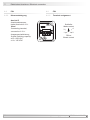
6 Elektrischer Anschluss/Electricalconnection
6.1 POG 90
6.1.2 Beschreibung der Anschlüsse
6.1.3 Ausgangssignale
6.1 POG 90
6.1.2 Terminal signicance
6.1.3 Output signals
+UB; +
Betriebsspannung
Voltage supply
; ; GND; 0 V
Masseanschluss
Ground
;
Erdungsanschluss (Gehäuse)
Earth ground (housing)
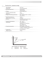
K1; A; A+
Ausgangssignal Kanal 1
Output signal channel 1
K1
; A; A-
Ausgangssignal Kanal 1 invertiert
Output signal channel 1 inverted
K2; B; B+
Ausgangssignal Kanal 2 (90° versetzt zu Kanal 1)
Output signal channel 2 (offset by 90° to channel 1)
K2
; B; B-
Ausgangssignal Kanal 2 invertiert
Output signal channel 2 inverted
K0; C; R; R+
Nullimpuls (Referenzsignal)
Zero pulse (reference signal)
K0
; C; R; R-
Nullimpuls invertiert
Zero pulse inverted
Signalfolge bei positiver
Drehrichtung, siehe Abschnitt 5.
Sequence for positive rotating
direction, see section 5.
K1
K1
K2
K2
K0
K0
90°
Seite wird geladen ...
Seite wird geladen ...
Seite wird geladen ...
Seite wird geladen ...
Seite wird geladen ...
Seite wird geladen ...
Seite wird geladen ...
Seite wird geladen ...
Seite wird geladen ...
Seite wird geladen ...
Seite wird geladen ...
Seite wird geladen ...
-
 1
1
-
 2
2
-
 3
3
-
 4
4
-
 5
5
-
 6
6
-
 7
7
-
 8
8
-
 9
9
-
 10
10
-
 11
11
-
 12
12
-
 13
13
-
 14
14
-
 15
15
-
 16
16
-
 17
17
-
 18
18
-
 19
19
-
 20
20
-
 21
21
-
 22
22
-
 23
23
-
 24
24
-
 25
25
-
 26
26
-
 27
27
-
 28
28
-
 29
29
-
 30
30
-
 31
31
-
 32
32


Hubner POG 90 + FSL Mounting And Operating Instructions
- Typ
- Mounting And Operating Instructions
- Dieses Handbuch eignet sich auch für
Andere Dokumente
-
Baumer TDP 0,09 + FSL Assembly Instruction
-
-
-
-
-
-
-
-
-