Baumer HOG 86 + FSL Installation and Operating Instructions
- Typ
- Installation and Operating Instructions

Montage- und Betriebsanleitung
Mounting and operating instructions
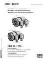
HOG 86 + FSL
Kombination
Inkrementaler Drehgeber mit integriertem
mechanischen Fliehkraftschalter
Combination
Incremental encoder with integrated
mechanical centrifugal switch
MB194.1 - 11138089
Baumer_HOG86-FSL_II_DE-EN (20A1)
Option EMS: LED
Option M: redundant +
Option EMS: LED

Baumer_HOG86-FSL_II_DE-EN (20A1)
MB194.1 - 11138089
Inhaltsverzeichnis
Inhaltsverzeichnis
1 Allgemeine Hinweise ................................................. 1
2 Sicherheitshinweise
..................................................3
3 Vorbereitung
...................................................................5
3.1 Lieferumfang
..............................................................5
3.2 Zur Montage erforderlich
(nicht im Lieferumfang enthalten)
.................... 6
3.3 Befestigungen für Drehmomentstütze
(nicht im Lieferumfang enthalten)
.................... 7
3.4 Zur Demontage erforderlich
(nicht im Lieferumfang enthalten)
.................... 8
3.5 Erforderliches Werkzeug
(nicht im Lieferumfang enthalten)
.................... 8
4 Montage
.............................................................................9
4.1 Montage der Drehmomentstütze
(Zubehör)
.....................................................................9
4.1.1 Mit Stützblech
...................................................9
4.1.1.1 Schritt 1
........................................................ 9
4.1.1.2 Schritt 2
..................................................... 10
4.1.2 Direkte Montage
........................................... 10
4.2 Montage des Erdungsbandes
(Zubehör)
...................................................................11
4.3 Montage an Antriebswelle
.................................11
4.3.1 Schritt 1
..............................................................11
4.3.2 Schritt 2
............................................................... 12
4.3.2.1 Einseitig offene Hohlwelle
............... 12
4.3.2.2 Konuswelle
.............................................. 13
4.3.3 Schritt 3
............................................................. 14
4.3.3.1 Montage mit Stützblech
.................... 14
4.3.3.2 Direkte Montage
................................... 14
4.3.4 Schritt 4
............................................................. 15
4.3.4.1 Montage mit Stützblech
.................... 15
4.3.4.2 Direkte Montage
................................... 16
4.3.5 Hinweis zur Vermeidung von
Messfehlern
..................................................... 17
4.3.6 Schritt 5
............................................................. 18
5 Abmessungen
............................................................. 19
5.1 Einseitig offene Hohlwelle
................................ 19
5.2 Konuswelle
............................................................... 19
5.3 Montagemöglichkeiten
....................................... 20
5.4 Stützbleche (Zubehör)
....................................... 20
6 Elektrischer Anschluss
........................................ 21
6.1 HOG 86
...................................................................... 21
6.1.1 Montage Anschlusskabel
......................... 21
6.1.2 Beschreibung der Anschlüsse
...............22
6.1.3 Ausgangssignale
.......................................... 22
6.1.4 Anschlussbelegung
..................................... 23
6.1.4.1 Standard
................................................... 23
6.1.4.2 Option EMS
............................................. 23
6.1.5 Option EMS (Enhanced Monitoring
System):
Status LED / Fehlerausgang
.................. 24
6.1.6 Sensorkabel HEK 8 (Zubehör)
.............. 25
6.2 FSL
............................................................................... 26
6.2.1 Montage Anschlusskabel
......................... 26
6.2.2 Klemmenbelegung
....................................... 26
7 Demontage
.................................................................... 27
7.1 Schritt 1
...................................................................... 27
7.2 Schritt 2
...................................................................... 28
7.3 Schritt 3
...................................................................... 28
7.4 Schritt 4
......................................................................29
7.5 Schritt 5
......................................................................29
7.6 Schritt 6
......................................................................30
7.7 Schritt 7
......................................................................30
7.8 Schritt 8
......................................................................30
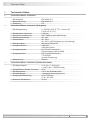
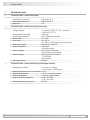
8 Technische Daten
..................................................... 31
8.1 Technische Daten - elektrisch
........................ 31
8.2 Technische Daten - elektrisch
(Drehgeber)
.............................................................. 31
8.3 Technische Daten - elektrisch
(Fliehkraftschalter)
............................................... 31
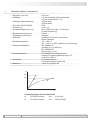
8.4 Technische Daten - mechanisch
.................. 32
9 Zubehör
........................................................................... 35

MB194.1 - 11138089
Baumer_HOG86-FSL_II_DE-EN (20A1)
Table of contents
Table of contents
1 General notes ................................................................. 2
2 Security indications
................................................... 4
3 Preparation
......................................................................5
3.1 Scope of delivery
.....................................................5
3.2 Required for mounting
(not included in scope of delivery)
..................6
3.3 Attachements for torque arm
(not included in scope of delivery)
..................7
3.4 Required for dismounting
(not included in scope of delivery)
..................8
3.5 Required tools
(not included in scope of delivery)
..................8
4 Mounting
............................................................................ 9
4.1 Mounting of the torque arm
(accessory)
..................................................................9
4.1.1 With support plate
........................................... 9
4.1.1.1 Step 1
............................................................ 9
4.1.1.2 Step 2
......................................................... 10
4.1.2 Direct mounting
............................................. 10
4.2 Mounting of the earthing strap
(accessory)
............................................................... 11
4.3 Mounting to drive shaft
...................................... 11
4.3.1 Schritt 1
............................................................. 11
4.3.2 Step 2
................................................................. 12
4.3.2.1 Blind hollow shaft
................................. 12
4.3.2.2 Cone shaft
............................................... 13
4.3.3 Step 3
................................................................. 14
4.3.3.1 Mounting with support plate
........... 14
4.3.3.2 Direct mounting
..................................... 14
4.3.4 Step 4
................................................................. 15
4.3.4.1 Mounting with support plate
........... 15
4.3.4.2 Direct mounting
..................................... 16
4.3.5 How to prevent measurement errors
. 17
4.3.6 Step 5
................................................................. 18
5 Dimensions
................................................................... 19
5.1. Blind hollow shaft
.................................................. 19
5.2 Cone shaft
................................................................ 19
5.3 Mounting possibilities
......................................... 20
5.4 Support plates (accessories)
.......................... 20
6 Electrical connection
............................................. 21
6.1 HOG 86
...................................................................... 21
6.1.1 Mounting connecting cable
..................... 21
6.1.2 Terminalsignicance
.................................. 22
6.1.3 Output signals
................................................ 22
6.1.4 Terminal assignment
.................................. 23
6.1.4.1 Standard
................................................... 23
6.1.4.2 Option EMS
............................................. 23
6.1.5 Option EMS (Enhanced Monitoring
System):
Status LED / Error output
......................... 24
6.1.6 Sensor cable HEK 8 (accessory)
......... 25
6.2 FSL
............................................................................... 26
6.2.1 Mounting connecting cable
..................... 26
6.2.2 Terminal assignment
.................................. 26
7 Dismounting
................................................................. 27
7.1 Step 1
.......................................................................... 27
7.2 Step 2
.......................................................................... 28
7.3 Step 3
.......................................................................... 28
7.4 Step 4
.......................................................................... 29
7.5 Step 5
.......................................................................... 29
7.6 Step 6
.......................................................................... 30
7.7 Step 7
.......................................................................... 30
7.8 Step 8
.......................................................................... 30
8 Technical data
............................................................. 33
8.1 Technical data - electrical ratings
................. 33
8.2 Technical data - electrical ratings
(encoder)
................................................................... 33
8.3 Technical data - electrical ratings
(centrifugal switch)
............................................... 33
8.4 Technical data - mechanical design
............ 34
9 Accessories
.................................................................. 35

1
Baumer_HOG86-FSL_II_DE-EN (20A1)
MB194.1 - 11138089
1 Allgemeine Hinweise
1 Allgemeine Hinweise
1.1 Zeichenerklärung:
Gefahr
Warnung bei möglichen Gefahren
Hinweis zur Beachtung
Hinweis zur Gewährleistung eines einwandfreien Betriebes des Gerätes
i
Information
Empfehlung für die Gerätehandhabung
1.2 Die Kombination HOG 86 + FSL ist ein opto-elektronisches Prä zi sionsmessgerät und ein
mechanisch wirkendes Schaltgerät, das mit Sorgfalt nur von technisch qualiziertem Per
sonal gehandhabt werden darf.
1.3 Die konstruktive Auslegung des Fliehkraftschalters ist die Verwendung als Schalter mit
Zwangsöffnerfunktion. Er darf nicht als Dauerschalter (Schaltzyklen größer 500 während
der Lebensdauer) verwendet werden.
1.4 Die zu erwartende Lebensdauer des Gerätes hängt von den Kugellagern ab, die mit einer
Dauerschmierung ausgestattet sind.
1.5
Der Lagertemperaturbereich des Gerätes liegt zwischen -15 °C bis +70 °C.
1.6
Der Betriebstemperaturbereich des Gerätes liegt zwischen -40 °C bis +100 °C
(>3072 Impulse pro Umdrehung: -25...+100 °C), am Gehäuse gemessen.
1.7
EU-Konformitätserklärung gemäß den europäischen Richtlinien.
1.8 Wir gewähren 2 Jahre Gewährleistung im Rahmen der Bedingungen des Zentralverbandes der
Elektroindustrie (ZVEI).
1.9 Wartungsarbeiten sind nicht erforderlich. Das Gerät darf nur wie in dieser Anleitung beschrie-
ben geöffnet werden. Reparaturen, die ein vollständiges Öffnen des Gerätes erfordern, sind
ausschließlich vom Hersteller durchzuführen. Am Gerät dürfen keine Veränderungen vorge-
nommen werden.
1.10 Bei Rückfragen bzw. Nachlieferungen sind die auf dem Typenschild des Gerätes angege-
benen Daten, insbesondere Typ und Seriennummer, unbedingt anzugeben.
1.11
Entsorgung (Umweltschutz):
Gebrauchte Elektro- und Elektronikgeräte dürfen nicht im Hausmüll entsorgt werden.
Das Produkt enthält wertvolle Rohstoffe, die recycelt werden können. Wenn immer
möglich sollen Altgeräte lokal am entsprechenden Sammeldepot entsorgt werden. Im
Bedarfsfall gibt Baumer den Kunden die Möglichkeit, BaumerProdukte fachgerecht zu entsor-
gen. Weitere Informationen siehe www.baumer.com.
i
Achtung!
Beschädigung des auf dem Gerät bendlichen Siegels führt zu Gewährleistungsver-
lust.

MB194.1 - 11138089
Baumer_HOG86-FSL_II_DE-EN (20A1)
2
General notes 1
1 General notes
1.1 Symbol guide:
Danger
Warnings of possible danger
General information for attention
Informations to ensure correct device operation
i
Information
Recommendation for device handling
1.2 The combination HOG 86 + FSL is an opto electro nic precision measurement device and a
mechanically operated switching device which must be handled with care by skilled person-
nel only.
1.3 The constructive design of the centrifugal switch is its use as a switch with positive break func-
tion. It must not be used as a continuous switch (switching cycles greater than 500 during
service life).
1.4 The expected service life of the device depends on the ball bearings, which are equipped with
a permanent lubrication.
1.5
The storage temperature range of the device is between -15 °C and +70 °C.
1.6
The operating temperature range of the device is between -40 °C and +100 °C
(>3072 pulses per revolution: -25...+100 °C), measured at the housing.
1.7
EU Declaration of Conformity meeting to the European Directives.
1.8 We grant a 2-year warranty in accordance with the regulations of the ZVEI (Central Association
of the German Electrical Industry).
1.9 Maintenance work is not necessary. The device may be only opened as described in this
instruction. Repair work that requires opening the device completely must be carried out by the
manufacturer. Alterations of the device are not permitted.
1.10 In the event of queries or subsequent deliveries, the data on the device type label must be
quoted, especially the type designation and the serial number.
1.11
Disposal (environmental protection):
Do not dispose of electrical and electronic equipment in household waste. The product
contains valuable raw materials for recycling. Whenever possible, waste electrical and
electronic equipment should be disposed locally at the authorized collection point. If
necessary, Baumer gives customers the opportunity to dispose of Baumer products profession-
ally. For further information see www.baumer.com.
i
Warning!
Damaging the seal on the device invalidates warranty.

3
Baumer_HOG86-FSL_II_DE-EN (20A1)
MB194.1 - 11138089
2 Sicherheitshinweise
2 Sicherheitshinweise
2.1 Verletzungsgefahr durch rotierende Wellen
Haare und Kleidungsstücke können von rotierenden Wellen erfasst werden.
• Vor allen Arbeiten alle Betriebsspannungen ausschalten und Maschinen stillsetzen.
2.2 Zerstörungsgefahr durch elektrostatische Auadung
Die elektronischen Bauteile im Gerät sind empndlich gegen hohe Spannungen.
• Steckkontakte und elektronische Komponenten nicht berühren.
• Ausgangsklemmen vor Fremdspannungen schützen.
• Maximale Betriebsspannung nicht überschreiten.
2.3 Zerstörungsgefahr durch mechanische Überlastung
Eine starre Befestigung kann zu Überlastung durch Zwangskräfte führen.
• Die Beweglichkeit des Gerätes niemals einschränken.
Unbedingt die Montagehinweise beachten.
• Die vorgegebenen Abstände und/oder Winkel unbedingt einhalten.
2.4 Zerstörungsgefahr durch mechanischen Schock
Starke Erschütterungen, z. B. Hammerschläge, können zur Zerstörung der Abtastung führen.
• Niemals Gewalt anwenden.
Bei sachgemäßer Montage lässt sich alles leichtgängig zusammenfügen.
• Für die Demontage geeignetes Abziehwerkzeug benutzen.
2.5 Zerstörungsgefahr durch Verschmutzung
Schmutz kann im Gerät zu Kurzschlüssen und zur Beschädigung der Abtastung führen.
• Während aller Arbeiten am Gerät auf absolute Sauberkeit achten.
• Niemals Öl oder Fett in das Innere des Gerätes gelangen lassen.
2.6 Zerstörungsgefahr durch klebende Flüssigkeiten
Klebende Flüssigkeiten können die Abtastung und die Kugellager beschädigen. Die Demontage
eines mit der Achse verklebten Gerätes kann zu dessen Zerstörung führen.
2.7 Explosionsgefahr
Das Gerät nicht in Bereichen mit explosionsgefährdeten bzw. leicht entzündlichen Mate-rialien
verwenden. Durch eventuelle Funkenbildung können diese leicht Feuer fangen und/oder explo-
dieren.

MB194.1 - 11138089
Baumer_HOG86-FSL_II_DE-EN (20A1)
4
Security indications 2
2 Security indications
2.1 Risk of injury due to rotating shafts
Hair and clothes may become tangled in rotating shafts.
• Before all work switch off all voltage supplies and ensure machinery is stationary.
2.2 Risk of destruction due to electrostatic charge
Electronic parts contained in the device are sensitive to high voltages.
• Do not touch plug contacts or electronic components.
• Protect output terminals against external voltages.
• Do not exceed maximum voltage supply.
2.3 Risk of destruction due to mechanical overload
Rigid mounting may give rise to constraining forces.
• Never restrict the freedom of movement of the device.
The mounting instructions must be followed.
• Itisessentialthatthespeciedclearancesand/oranglesareobserved.
2.4 Risk of destruction due to mechanical shock
Violent shocks, e. g. due to hammer impacts, can lead to the destruction of the sensing system.
• Never use force.
Mounting is simple when correct procedure is followed.
• Use suitable puller for dismounting.
2.5 Risk of destruction due to contamination
Dirt penetrating inside the device can cause short circuits and damage the sensing system.
• Absolute cleanliness must be maintained when carrying out any work on the device.
• Never allow lubricants to penetrate the device.
2.6 Risk of destruction due to adhesive uids
Adhesiveuidscandamagethesensingsystemandtheballbearings.Dismountingadevice,
secured to a shaft by adhesive may lead to the destruction of the device.
2.7 Explosion risk
Do not use the device in areas with explosive and/or highly infammable materials. They may
explode and/or catch fre by possible spark formation.

5
Baumer_HOG86-FSL_II_DE-EN (20A1)
MB194.1 - 11138089
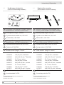
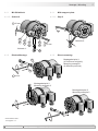
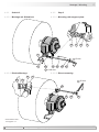
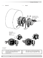
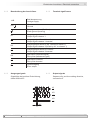
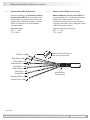
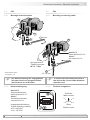
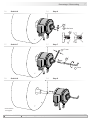
1
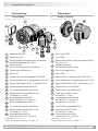
Gehäuse HOG 86
2
Abdeckung FSL
3
Einseitig offene Hohlwelle oder Konuswelle
mit Schlüsseläche SW 13 mm
4
Spannelement
(nur bei einseitig offener Hohlwelle)
5
Torxschraube M4x10 mm
6
Rotor FSL
7
Scheibe A4,3 für Erdungsband, ISO 7090
8
Schraube M4x6 mm für Erdungsband, ISO 1207
9
Option EMS: Status LED
1)
, s. Abschnitt 6.1.5.
10a
Klemmenkastendeckel HOG 86
10b
Torx-/Schlitzschraube M4x32 mm
10c
Kabelverschraubung M20x1,5 mm
für Kabel ø5...13 mm
10d
Anschlussplatine HOG 86,
siehe Abschnitt 6.1.1 und 6.1.4.
11a
Klemmenkastendeckel FSL
11b
Torx-/Schlitzschraube M4x32 mm
11c
Kabelverschraubung M20x1,5 mm
für Kabel ø5...13 mm
11d
Anschlussklemmen FSL,
siehe Abschnitt 6.2.1 und 6.2.2.
1)
Option EMS: HOG 86.2 + FSL
2)
Option M: Redundante Abtastung HOG 86 M + FSL
1
Housing HOG 86
2
Cover FSL
3
Blind hollow shaft or cone shaft with spanner
at13mma/f
4
Clamping element
(only for blind hollow shaft)
5
Torx screw M4x10 mm
6
Rotor FSL
7
Washer A4.3 for earthing strap, ISO 7090
8
Screw M4x6 mm for earthing strap, ISO 1207
9
Option EMS: Status LED
1)
, see section 6.1.5.
10a
Terminal box cover HOG 86
10b
Torx/slotted screw M4x32 mm
10c
Cable gland M20x1.5 mm
for cable ø5...13 mm
10d
Connecting board HOG 86,
see section 6.1.1 and 6.1.4.
11a
Terminal box cover FSL
11b
Torx/slotted screw M4x32 mm
11c
Cable gland M20x1.5 mm
for cable ø5...13 mm
11d
Connecting terminal FSL,
see section 6.2.1 and 6.2.2.
1)
Option EMS: HOG 86.2 + FSL
2)
Option M: Redundant sensing HOG 86 M + FSL
3 Vorbereitung / Preparation
3 Vorbereitung
3.1 Lieferumfang
3 Preparation
3.1 Scope of delivery
1
2
2
7
8
10a 10b
9a
9d
10d
5
4
10c
11c
11b
11a
11d
3
6
-
2)
1)
2)
9

MB194.1 - 11138089
Baumer_HOG86-FSL_II_DE-EN (20A1)
6
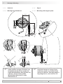
Vorbereitung / Preparation 3
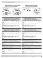
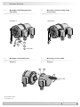
12
Montageset Erdungsband als Zubehör erhältlich:
Bestellnummer 11071906, bestehend aus ...
12a
Erdungsband, Länge ~230 mm
12b
Zylinderschraube M6x8 mm, ISO 1207
12c
Scheibe B6,4, ISO 7090
13
Montage-/Demontageset als Zubehör erhältlich:
Bestellnummer 11077087, bestehend aus ...
13a
Zylinderschraube M6x30 mm, ISO 4762
13b
Federring 6, DIN 7980
14
3)
Drehmomentstütze, als Zubehör erhältlich:
Bestellnummer Länge L, Version
11043628 67...70 mm, Standard
11004078 125 (±5) mm
4)
, Standard
11002915 440 (+20/-15) mm
5)
, Standard
11054917 67...70 mm, isoliert
11072795 125 (±5) mm
4)
, isoliert
11082677 440 (+20/-15) mm
5)
, isoliert
11054918 67...70 mm, rostfrei
11072787 125 (±5) mm
4)
, rostfrei
11072737 440 (+20/-15) mm
5)
, rostfrei
15
HEK 8 Sensorkabel, als Zubehör erhältlich
16
Anschlusskabel für FSL
3)
Passende Befestigungen siehe Abschnitt 3.3.
4)
Kürzbar auf ≥71 mm
5)
Kürzbar auf ≥131 mm
12
Mounting kit earthing strap available as ac-
cessory: Order number 11071906, including ...
12a
Earthing strap, length ~230 mm
12b
Cylinder screw M6x8 mm, ISO 1207
12c
Washer B6.4, ISO 7090
13
Mounting/dismounting kit available as acces-
sory: Order number 11077087, including ...
13a
Cylinder screw M6x30 mm, ISO 4762
13b
Spring washer 6, DIN 7980
14
3)
Torque arm, available as accessory:
Order number Length L, version
11043628 67...70 mm, standard
11004078 125 (±5) mm
4)
, standard
11002915 440 (+20/-15) mm
5)
, standard
11054917 67...70 mm, insulated
11072795 125 (±5) mm
4)
, insulated
11082677 440 (+20/-15) mm
5)
, insulated
11054918 67...70 mm, stainless
11072787 125 (±5) mm
4)
, stainless
11072737 440 (+20/-15) mm
5)
, stainless
15
HEK 8 sensor cable, available as accessory
16
Connecting cable for FSL
3)
Suitable attachements see section 3.3.
4)
Canbeshortenedto≥71mm
5)
Canbeshortenedto≥131mm
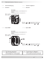
3.2 Zur Montage erforderlich
(nicht im Lieferumfang enthalten)
3.2 Required for mounting
(not included in scope of delivery)
13
13b 13a
12
12c
12a
12b
14
15
16
L
3)

7
Baumer_HOG86-FSL_II_DE-EN (20A1)
MB194.1 - 11138089
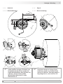
3 Vorbereitung / Preparation
3.3 Befestigungen für Drehmomentstütze
(nicht im Lieferumfang enthalten)
3.3 Attachements for torque arm
(not included in scope of delivery)
17
Stützblech-Montageset R63 für Drehmoment-
stütze Größe M6, als Zubehör erhältlich:
Bestellnummer 11071850, bestehend aus ...
17a
Stützblech R63 (Montageradius 63 mm)
17b
Linsensenkschraube M4x8 mm, ISO 7047
17c
Sechskantschraube M6x18 mm, ISO 4017
17d
Selbstsichernde Mutter M6, ISO 10511
17e
Scheibe A6,4, ISO 7090
18
Stützblech-Montageset R69 für Drehmoment-
stütze Größe M6, als Zubehör erhältlich:
Bestellnummer 11082676, bestehend aus ...
18a
Stützblech R69 (Montageradius 69 mm)
18b
Linsensenkschraube M4x8 mm, ISO 7047
18c
Sechskantschraube M6x18 mm, ISO 4017
18d
Selbstsichernde Mutter M6, ISO 10511
18e
Scheibe A6,4, ISO 7090
19
Schraubmontageset für Drehmomentstütze
Größe M6, als Zubehör erhältlich:
Bestellnummer 11072076, bestehend aus ...
19a
Passschraube ISO 7379 von 6 mm auf M5
19b
Scheibe B6,4, IS0 7090
20
Montageset für Drehmomentstütze Größe M6,
als Zubehör erhältlich:
Bestellnummer 11071904, bestehend aus ...
20a
Gewindestange M6 (1.4104),
Länge variabel (≤210 mm)
20b
Scheibe B6,4, IS0 7090
20c
Selbstsichernde Mutter M6, ISO 10511
17
Support plate mounting kit R63 for torque arm
size M6, available as accessory:
Order number 11071850, including ...
17a
Support plate R63 (mounting radius 63 mm)
17b
Raised countersunk-head screw M4x8 mm, ISO 7047
17c
Hexagon screw M6x18 mm, ISO 4017
17d
Self-locking nut M6, ISO 10511
17e
Washer A6.4, ISO 7090
18
Support plate mounting kit R69 for torque arm
size M6, available as accessory:
Order number 11082676, including ...
18a
Support plate R69 (mounting radius 69 mm)
18b
Raised countersunk-head screw M4x8 mm, ISO 7047
18c
Hexagon screw M6x18 mm, ISO 4017
18d
Self-locking nut M6, ISO 10511
18e
Washer A6.4, ISO 7090
19
Screw mounting kit for torque arm size M6,
available as accessory:
Order number 11072076, including ...
19a
Fitting screw ISO 7379 from 6 mm to M5
19b
Washer B6.4, IS0 7090
20
Mounting kit for torque arm size M6, available
as accessory:
Order number 11071904, including ...
20a
Thread rod M6 (1.4104),
lengthvariable(≤210mm)
20b
Washer B6.4, IS0 7090
20c
Self-locking nut M6, ISO 10511
17b
17a
17d
17
17e 17c
18b
18a
18d
18
18e 18c
19
19b 19a
20
20b 20c
20a
3x
2x 2x
3x
2x

MB194.1 - 11138089
Baumer_HOG86-FSL_II_DE-EN (20A1)
8
Vorbereitung / Preparation 3
13
Montage-/Demontageset als Zubehör erhält-
lich:
Bestellnummer 11077087, bestehend aus ...
13c
Gewindestift M6x10 mm, ISO 7436
13d
Zylinderschraube M8x45 mm, ISO 4762
13
Mounting/dismounting kit available as acces-
sory:
Order number 11077087, including ...
13c
Setscrew M6x10 mm, ISO 7436
13d
Cylinder screw M8x45 mm, ISO 4762
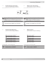
3.4 Zur Demontage erforderlich
(nicht im Lieferumfang enthalten)
3.4 Required for dismounting
(not included in scope of delivery)
3.5 Erforderliches Werkzeug
(nicht im Lieferumfang enthalten)
3.5 Required tools
(not included in scope of delivery)
13
13c 13d
verschiedene Größen
6)
verschiedene Größen
6)
verschiedene Größen
6)
verschiedene Größen
6)
verschiedene Größen
6)
6)
Siehe Montage- und Demontageschritte
21
Werkzeugset als Zubehör erhältlich:
Bestellnummer 11068265
various sizes
6)
various sizes
6)
various sizes
6)
various sizes
6)
various sizes
6)
6)
See mounting and dismounting steps
21
Tool kit available as accessory:
Order number 11068265

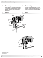
4 Montage / Mounting
9
Baumer_HOG86-FSL_II_DE-EN (20A1)
MB194.1 - 11138089
4 Montage
In den Bildern am Beispiel vom HOG 86
+ FSL. Gleiche Montageschritte bei den
anderen Versionen, wenn nicht anders
angegeben.
4.1 Montage der Drehmomentstütze
(Zubehör)
4.1.1 Mit Stützblech
4.1.1.1 Schritt 1
4 Mounting
Pictures showing the HOG 86 + FSL as
example. Same mounting steps for all
other versions, unless otherwise stated.
4.1 Mounting of the torque arm
(accessory)
4.1.1 With support plate
4.1.1.1 Step 1
17a17b
18a18b
**
**
* Siehe Seite 7
See page 7
Montagebeispiel 1
(12 Positionen möglich)
Mounting example 1
(12 different positions)
Montagebeispiel 2
Mounting example 2
Montagebeispiel 3
Mounting example 3
Anzugsmoment:
Tightening torque:
M
t
= 2...3 Nm
PH 1

Montage / Mounting 4
MB194.1 - 11138089
Baumer_HOG86-FSL_II_DE-EN (20A1)
10
4.1.1 Mit Stützblech
4.1.1.2 Schritt 2
4.1.2 Direkte Montage
4.1.1 With support plate
4.1.1.2 Step 2
4.1.2 Direct mounting
Montagebeispiel 1
(4 Positionen möglich)
Mounting example 1
(4 different positions)
Montagebeispiel 2
Mounting example 2
Montagebeispiel 3
Mounting example 3
* Siehe Seite 6 oder 7
See page 6 or 7
17d
17a
17e 17c
18d
18a
18e 18c
14
14
*
*
* *
*
*
*
*
* *
*
*
Variante 1:
Variante 2:
19b
19a
10 mm
10 mm
4 mm

4 Montage / Mounting
11
Baumer_HOG86-FSL_II_DE-EN (20A1)
MB194.1 - 11138089
* Siehe Seite 5 oder 6
See page 5 or 6
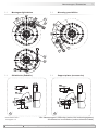
4.2 Montage des Erdungsbandes
(Zubehör)
4.3 Montage an Antriebswelle
4.3.1 Schritt 1
4.2 Mounting of the earthing strap
(accessory)
4.3 Mounting to drive shaft
4.3.1 Schritt 1
Variante 1: Variante 2:
12c
12c
12c
*
*
*
2 5
* *
TX 20
1.6x8 mm

Montage / Mounting 4
MB194.1 - 11138089
Baumer_HOG86-FSL_II_DE-EN (20A1)
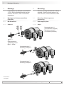
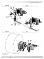
12
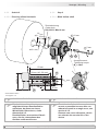
4.3.2 Schritt 2
4.3.2.1 Einseitig offene Hohlwelle
4.3.2 Step 2
4.3.2.1 Blind hollow shaft
Zentrierbohrung
Center hole
DIN 332-D, M6x16 mm
4
*
M6
≥ ø20 mm
ø16
h6
mm
ø16
h6
mm
52 mm (40...52 mm)
53 mm
16 mm
4
3
*
*
* Siehe Seite 5 oder 6
See page 5 or 6
Anzugsmoment:
Tightening torque:
M
t
= 6 Nm
13b 13a
* *
52 mm
(40...52 mm)
13 mm
5 mm
Antriebswelle einfetten. Lubricate drive shaft.
Die Antriebswelle sollte einen
möglichst kleinen Rundlauffehler
aufweisen, da dieser zu einem
Winkelfehler führen kann, siehe
Abschnitt 4.3.5.
Rundlauffehler verursachen Vibrati-
onen, die die Lebensdauer des
Gerätes verkürzen können.
The drive shaft should have as less
runout as possible because this can
otherwise result in an angle error, see
section 4.3.5.
Runouts can cause vibrations, which
can shorten the service life of the
device.

4 Montage / Mounting
13
Baumer_HOG86-FSL_II_DE-EN (20A1)
MB194.1 - 11138089
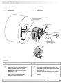
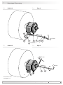
20 mm
1:10
ø17
JS8
mm
Zentrierbohrung
Center hole
DIN 332-D, M6x16 mm
Anzugsmoment:
Tightening torque:
M
t
= 3...4 Nm
13b
13a
*
*
4.3.2 Schritt 2
4.3.2.2 Konuswelle
4.3.2 Step 2
4.3.2.2 Cone shaft
* Siehe Seite 6
See page 6
Antriebswelle einfetten. Lubricate drive shaft.
Die Antriebswelle sollte einen
möglichst kleinen Rundlauffehler
aufweisen, da dieser zu einem
Winkelfehler führen kann, siehe
Abschnitt 4.3.5.
Rundlauffehler verursachen Vibrati-
onen, die die Lebensdauer des
Gerätes verkürzen können.
The drive shaft should have as less
runout as possible because this can
otherwise result in an angle error, see
section 4.3.5.
Runouts can cause vibrations, which
can shorten the service life of the
device.
13 mm
5 mm

Montage / Mounting 4
MB194.1 - 11138089
Baumer_HOG86-FSL_II_DE-EN (20A1)
14
12a
12b12c
*
**
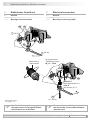
4.3.3 Schritt 3
4.3.3.1 Montage mit Stützblech
4.3.3 Step 3
4.3.3.1 Mounting with support plate
4.3.3.2 Direkte Montage 4.3.3.2 Direct mounting
20a
20c
20b 20b
14
20b20a
14
14
20b 20c
*
*
** * *
***
*
* *
* Siehe Seite 6 oder 7
See page 6 or 7
20b
20b
* *
*
20c
14
*
20c
10 mm
10 mm
1.6x8 mm

4 Montage / Mounting
15
Baumer_HOG86-FSL_II_DE-EN (20A1)
MB194.1 - 11138089
The torque arm should be mounted
free from clearance. A play of just
±0.03 mm, results in a runout of the
device of 0.06 mm. That may lead to a
large angle error, see section 4.3.5.
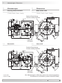
4.3.4 Schritt 4
4.3.4.1 Montage mit Stützblech
4.3.4 Step 4
4.3.4.1 Mounting with support plate
15°
15°
L1
L2 (≥L1)
9°
9°
9°
9°
Die Montage der Drehmomentstütze
sollte spielfrei erfolgen. Ein Spiel von
beispielsweise ±0,03 mm entspricht
einem Rundlauffehler des Gerätes von
0,06 mm, was zu einem großen
Winkelfehler führen kann, siehe
Abschnitt 4.3.5.

Montage / Mounting 4
MB194.1 - 11138089
Baumer_HOG86-FSL_II_DE-EN (20A1)
16
4.3.4 Schritt 4
4.3.4.2 Direkte Montage
4.3.4 Step 4
4.3.4.2 Direct mounting
9°
9°
9°
9°
Die Montage der Drehmomentstütze
sollte spielfrei erfolgen. Ein Spiel von
beispielsweise ±0,03 mm entspricht
einem Rundlauffehler des Gerätes von
0,06 mm, was zu einem großen
Winkelfehler führen kann, siehe
Abschnitt 4.3.5.
The torque arm should be mounted
free from clearance. A play of just
±0.03 mm, results in a runout of the
device of 0.06 mm. That may lead to a
large angle error, see section 4.3.5.
15°
15°
L1
L2 (≥L1)

4 Montage / Mounting
17
Baumer_HOG86-FSL_II_DE-EN (20A1)
MB194.1 - 11138089
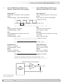
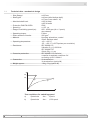
4.3.5 Hinweis zur Vermeidung von Messfeh-
lern
Für einen einwandfreien Betrieb des
Gerätes ist eine korrekte Montage, ins-
besondere auch der Drehmomentstütze,
notwendig, wie beschrieben in Abschnitt
4.1 und 4.3.4.
Der Rundlauffehler der Antriebswelle
sollte möglichst nicht mehr als 0,2 mm
(0,03 mm empfohlen) betragen, da hier-
durch Winkelfehler verursacht werden.
Solche Winkelfehler können durch einen
größeren Abstand L1 reduziert werden
7)
.
Dabei ist zu beachten, dass die Länge L2
der Drehmomentstütze, siehe Abschnitt
5.5, mindestens gleich L1 sein sollte
8)
.
Der Winkelfehler kann wie folgt berechnet
werden:
Δρ
mech
= ± 90°/π · R/L1
mit R:
Rundlauffehler in mm
L1:
Abstand der Drehmomentstütze zum
Gerätemittelpunkt in mm
Berechnungsbeispiel:
Für R = 0,06 mm und L1 = 63 mm ergibt
sich ein Winkelfehler Δρ
mech
von ± 0,027°.
i
Weitere Informationen erhalten Sie
unter der Telefon-Hotline
+49 (0)30 69003-111
4.3.5 How to prevent measurement errors
To ensure that the device operates cor-
rectly, it is necessary to mount it ac-
curately as described in section 4.1 and
4.3.4, which includes correct mounting of
the torque arm.
The radial runout of the drive shaft should
not exceed 0.2 mm (0.03 mm recom-
mended), if at all possible, to prevent an
angle error.
An angle error may be reduced by
increasing the length of L1
7)
. Make sure
that the length L2 of the torque arm, see
section 5.5, is at least equal to L1
8)
.
The angle error can be calculated as
follows:
Δρ
mech
= ± 90°/π · R/L1
with R:
Radial runout in mm
L1:
Distance of the torque arm to the center
point of the device in mm
Example of calculation:
For R = 0.06 mm and L1 = 63 mm the re-
sultingangleerrorΔρ
mech
equals ± 0.027°.
i
For more information,
call the telephone hotline at
+49 (0)30 69003-111
7)
Auf Anfrage wären verschiedene Stützbleche für die
Drehmomentstütze möglich.
8)
Wenn L2 < L1 muss mit der Länge L2 gerechnet werden.
7)
For this different support plates for the torque arm are
available on request.
8)
If L2 < L1, L2 must be used in the calculation formula.
Seite wird geladen ...
Seite wird geladen ...
Seite wird geladen ...
Seite wird geladen ...
Seite wird geladen ...
Seite wird geladen ...
Seite wird geladen ...
Seite wird geladen ...
Seite wird geladen ...
Seite wird geladen ...
Seite wird geladen ...
Seite wird geladen ...
Seite wird geladen ...
Seite wird geladen ...
Seite wird geladen ...
Seite wird geladen ...
Seite wird geladen ...
Seite wird geladen ...
Seite wird geladen ...
Seite wird geladen ...
-
 1
1
-
 2
2
-
 3
3
-
 4
4
-
 5
5
-
 6
6
-
 7
7
-
 8
8
-
 9
9
-
 10
10
-
 11
11
-
 12
12
-
 13
13
-
 14
14
-
 15
15
-
 16
16
-
 17
17
-
 18
18
-
 19
19
-
 20
20
-
 21
21
-
 22
22
-
 23
23
-
 24
24
-
 25
25
-
 26
26
-
 27
27
-
 28
28
-
 29
29
-
 30
30
-
 31
31
-
 32
32
-
 33
33
-
 34
34
-
 35
35
-
 36
36
-
 37
37
-
 38
38
-
 39
39
-
 40
40


Baumer HOG 86 + FSL Installation and Operating Instructions
- Typ
- Installation and Operating Instructions
in anderen Sprachen
- English: Baumer HOG 86 + FSL
Verwandte Artikel
-
Baumer HOGS 75 KC Assembly Instruction
-
-
-
-
-
-
-
-
-
