Beninca SCP30QIS/SCP30QES Benutzerhandbuch
- Typ
- Benutzerhandbuch

SC.P30QIS
SC.P30QES
L8542339
Rev. 11/07/01
40-60cm
Fig.1
Fig.2
1
2
1
2
3
5
4
+
+
-
24Vac-Vdc
C
NO NC
TX
RX
+
24Vac-Vdc
+
-
COM
NO
NC
3
4
5
Fig.3
Fig.5 Fig.6
COM
COM
Power
OFF
NO
NO
NC
NC
4
3
5
3
5
4
LED
A
B
JP2 Open
SYNC OFF
SYNC
JP2 Open
SYNC OFF
SYNC
Fig.4
+
-
C
NO NC
+
-
JP2 Close
SYNC ON
SYNC
JP2 Close
SYNC ON
SYNC
TX1 RX1
+
-
C
NO NC
+
-
JP2 Close
SYNC ON
SYNC
JP2 Close
SYNC ON
SYNC
TX2 RX2
24 Vac
+
-
C
NO NC
+
-
JP2 Close
SYNC ON
SYNC
JP2 Close
SYNC ON
SYNC
TX1 RX1
+
-
C
NO NC
+
-
JP2 Close
SYNC ON
SYNC
JP2 Close
SYNC ON
SYNC
TX2 RX2
24 Vac
+
-
C
NO NC
+
-
JP2 Close
SYNC ON
SYNC
JP2 Close
SYNC ON
SYNC
TX3 RX3
+
-
C
NO NC
+
-
JP2 Close
SYNC ON
SYNC
JP2 Close
SYNC ON
SYNC
TX4 RX4
TX1
TX2
RX1
RX2
TX1
TX2
RX1
RX2
RX3
RX4
TX3
TX4
ITALIANO
FOTODISPOSITIVI DA INCASSO E DA ESTERNO A
LUCE MODULATA CON DUE RELE’
DESCRIZIONE
Fotodispositivo costituito da un ricevitore e da un trasmettitore a luce
infrarossa modulata.
Il corretto allineamento della coppia trasmettitore-ricevitore viene visua-
lizzato da un led sul ricevitore: è quindi possibile una facile e accurata
installazione.
POSSIBILITA’ DI IMPIEGO
Viene impiegato per la protezione di porte, cancelli e accessi automatizzati
in genere.
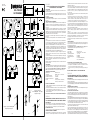
INSTALLAZIONE E ALLINEAMENTO
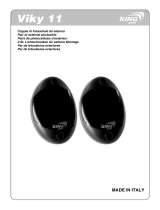
1) Murare o ssare con le apposite quattro viti il contenitore dei dispositivi,
tenendo conto che per una corretta installazione il trasmettitore e il rice-
vitore devono essere montati in posizione frontale e allineati sullo stesso
asse (g. 1).
2) Far passare i cavi di collegamento attraverso il contenitore e collegarli
alle rispettive morsettiere del trasmettitore e del ricevitore (gura 2), preoc-
cupandosi che i cavi siano più corti possibile, evitando di farli passare
nelle vicinanze di potenziali fonti di disturbo (es. motori ) e possibilmente
montando il ricevitore vicino alla centralina.
3) Inserire nel contenitore la parte ottico/elettronica e ssarla con le ap-
posite viti.
4) Alimentare i fotodispositivi alla tensione di alimentazione di 24Vdc o
24Vac.
Se il collegamento è stato effettuato correttamente si accenderà il led ros-
so sul ricevitore e il contatto NC (morsetti 3 e 5 del ricevitore) sarà chiuso.
La g.3 esemplica i due possibili stati dei contatti delle uscite relè.
5) Nel caso che la distanza di lavoro sia contenute (inferiore a circa 5-8 me-
tri) o quando ci sono parti riettenti vicine che possono disturbare il corret-
to funzionamento del sistema, inserire il dischetto attenuatore (Fig.4- A) in
gomma nella sede posta davanti alla lente del ricevitore. Il disco attenuato-
re può risultare utile anche per la schermatura da raggi solari.
6) Regolare la centratura del fascio agendo sulle apposite viti poste a
triangolo (Fig.4-B), in modo tale che il led rosso del ricevitore rimanga
sempre acceso.
7) Vericare il funzionamento del sistema, interrompendo più volte il raggio
infrarosso frapponendo un ostacolo tra il trasmettitore e il ricevitore; con-
trollare la conseguente commutazione dei relè e lo spegnimento del led
rosso sul ricevitore.
8) Montare ad incastro i frontalini di protezione e ricontrollare il funziona-
mento del sistema.
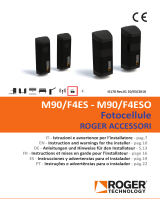
SINCRONISMO
Per evitare interferenze nel caso di utilizzo di due coppie di fotocellule ravvi-
cinate, attivare il sincronismo chiudendo i jumper JP2 sia sui trasmettitori sia
sui ricevitori. Il sincronismo funziona esclusivamente con alimentazione
24Vac con polarità invertita tra le due coppie come indicato in Fig. 5/6.
CARATTERISTICHE TECNICHE:
Alimentazione: 24Vac/Vdc +/-15%
Contatti relè: 1A MAX. a 24Vcc / 0.5A a 120Vca
Temp.di funzionamento: -10C°/+65C°
Assorbimento ricevitore: 40mA MAX
Assorbimento trasmettitore: 50mA MAX
Portata: 30 metri (senza disco attenuatore)
15 metri (con disco attenuatore
NOTE D’USO E AVVERTENZE:
• L’utilizzo del dischetto attenuatore comporta una riduzione di portata
pari a circa il 40%
• Al termine dell’installazione vericare il corretto funzionamento del di-
spositivo in modo da non creare pericolo a persone o cose.
• In caso di pioggia, nebbia o polvere la portata del fotodispositivo può
diminuire no al 50%.
N.B.: PRODOTTO ADATTO ALLA SOLA APPLICAZIONE APRICANCELLO.
ENGLISH
EMBEDDED PHOTODEVICES AND PHOTOCELLS FOR OU-
TDOOR USE WITH MODULATED LIGHT AND TWO RELAYS
DESCRIPTION
Photocell made of a receiver and a modulated infrared light transmitter.
The correct alignment of the transmitter-receiver pair is shown through a
LED on the receiver, thus ensuring an easy and accurate installation.
POSSIBILITY OF USE
It is used to protect doors, gates and automated accesses in general.
INSTALLATION AND ALIGNMENT
1) Embed the device container into the wall or x it by means of the special
four screws. It should be kept in mind that, for a correct installation, the
transmitter and the receiver must be assembled one in front of the other or
aligned on the same axis.
2) Insert the connecting cables through the container and connect them
to the relevant terminal strips of the transmitter and the receiver (gure 2).
The cables should be as short as possible, avoiding to make them run near
interference sources (e.g. motors). Possibly assemble the receiver near
the control unit.
3) Insert the optical/electronic element in the container and t it by means
of the special screws.
4) Power the photocells at a power voltage of 24VDC or “24VAC. If the
connection has been correctly carried out, the red LED on the receiver
switches on and the NC contact (terminals 3 and 5 on the receiver) is clo-
sed. Figure 3 shows two possible status of the relay output contacts.
5) Should the working distance be reduced (lower than approx. 5-8 me-
tres) or if reecting elements are near which might interfere with the correct
operation of the system, insert the dimming rubber disc (Fig.4- A) in the
hollow in front of the receiver lens. The dimming disc can be useful also to
protect the unit from direct sunlight.
6) Adjust the correct centring of the beam by using the special screws
places in a triangle, (Fig.4-B) so that the red LED of the receiver stays
always on.
7) Check the correct operation of the system by placing an obstacle
between the transmitter and the receiver various times, thus causing the
interruption of the infrared beam; check that, as a consequence of this, the
relay triggers and the red LED on the receiver switches off.
8) Clip the protection aps on the unit and check the correct operation of
the system.
SYNCHRONIZATION
To avert any interference when using two pairs of photocells mounted close
together, activate the synchronization function by closing the jumpers J2 on
both transmitters and receivers.
The synchronization operates only with 24Vac power supply and re-
versed polarity between the two pairs, as shown in Fig. 5/6.
SPECIFICATIONS
Power supply: 24Vac/Vdc +/-15%
Relay contacts: 1A MAX. a 24Vcc / 0.5A a 120Vca
Operating temperature: -10C°/+65C°
Receiver absorption: 40mA MAX
Transmitter absorption: 50mA MAX
Range: 30 m (without dimming disc)
15 m (with dimming disc).
INSTRUCTIONS FOR USE AND WARNING NOTES
• The use of the dimming disc causes a range reduction of about 40%.
• At completion of the installation, check the correct operation of the de-
vice, in order to avert any hazard to people or objects.
• In the event of rain, fog or dust, the photocell range may reduce up to
50%.
N.B. THIS ITEM IS SUITED TO ONLY OPEN THE GATE
DEUTSCH
FOTOZELLENEINRICHTUNG FÜR UP- ODER WANDAU-
SFÜHRUNG MIT LICHTMODULATION MIT ZWEI RELAIS
BESCHREIBUNG
Die Fotozelleneinheit besteht aus einem Empfänger und einem Sender mit
infraroter Lichtmodulation.
Die richtige Ausrichtung des Senders und des Empfängers wird durch eine
Leuchte am Empfänger gemeldet: dadurch wird die Installation erheblich
vereinfacht.
ANWENDUNGSMÖGLICHKEITEN
Die Einheit wird zum Schutz von Türen, Toren und allgemein für motorge-
steuerte Vorrichtungen verwendet.
INSTALLATION UND AUSRICHTUNG
1) Die Einheit einmauern oder mit den entsprechenden vier Schrauben
den Kasten der Einheit befestigen. Zur einwandfreien Installation müssen
der Sender und der Empfänger frontal montiert und auf derselben Achse
ausgerichtet sein.
2) Die Verbindungskabel durch den Kasten führen und an die entsprechen-
den Klemmleisten des Senders und des Empfängers schließen (Abbildung
2). Dabei sollten die Kabel so kurz wir möglich sein und nicht in der Nähe
von Störungsquellen verlegt werden (z.B. Motoren). Der Empfänger sollte
so nahe wie möglich neben der Einheit montiert werden.
3) In den Kasten das optische/elektronische Teil einsetzen und mit den
entsprechenden Schrauben befestigen.
4) Die Fotozelleneinrichtung mit einer Speisespannung von 24VDC oder
24VAC speisen. Wenn die Einrichtung richtig angeschlossen worden ist,
leuchtet die rote Leuchte am Empfänger auf und der Ruhekontakt (NC)
(Klemmen 3 und 5 des Empfängers) bleibt geschlossen. Die Abbildung 3
zeigt die zwei möglichen Zustände der Kontakte der Relaisausgänge.
5) Falls der Betriebszustand beschränkt ist (weniger als 5-8 Meter beträgt)
2 coppie - 2 pairs - 2 fotozellenpaare
2 couples - 2 paejas - 2 par
2+2 coppie - 2+2 pairs
2+2 fotozellenpaare - 2+2 couples
2+2 paejas - 2+2 par

oder wenn sich in der Nähe rückstrahlende Teile benden, die den einwan-
dfreien Betrieb des Systems beeinträchtigen könnten, eine Dämpfungs-
scheibe aus Gummi (Abb .4- A) in den Sitz vor der Linse des Empfängers
einsetzen. Die Dämpfungsscheibe kann auch als Abschirmung vor Son-
nenstrahlen nützlich sein.
6) Den Lichtstrahl durch die entsprechenden im Dreieck angebrachten
Schrauben einstellen (Abb.4- B), so dass die rote Leuchte des Empfängers
ständig eingeschaltet bleibt.
7) Den Betrieb des Systems kontrollieren und dazu mehrmals den Licht-
strahl mit einem Hindernis zwischen Sender und Empfänger unterbre-
chen; kontrollieren, ob dabei das Relais umschaltet und die rote Leuchte
am Empfänger ausschaltet.
8) Die Frontplatten einrasten und den Betrieb des Systems nochmals
kontrollieren.
SYNCHRONISMUS
Falls zwei nahliegende Fotozellenpaare verwendet werden, den Synchroni-
smus aktivieren, um Störungen zu vermeiden. Dazu die Jumpers JP2 an den
Sendegeräten und an den Empfängern schließen.
Der Synchronismus funktioniert ausschließlich mit einem Netzgerät
24Vac mit umgetauschten Polenpaaren, wie in Abb. 5/6 gezeigt.
TECHNISCHE EIGENSCHAFTEN:
Speisung: 24Vac/Vdc +/-15%
Relaiskontakte: 1A MAX. a 24Vcc / 0.5A a 120Vca
Betriebstemperatur: -10C°/+65C°
Stromaufnahme Empfänger: 40mA MAX
Stromaufnahme Sender: 50mA MAX
Tragweite: 30 m ( ohne Dämpfungsscheibe )
15 Meter (mit Dämpfungsscheibe)
GEBRAUCHSANWEISUNGEN UND HINWEISE
• Wenn die Dämpfungsscheibe verwendet wird, verringert sich die Tra-
gweite um ca. 40%.
• Nachdem die Installation beendet worden ist, kontrollieren ob die Vorri-
chtung richtig funktioniert und keine Gefahr für Menschen oder Gegen-
stände darstellen kann.
• Bei Regen, Nebel oder Staub, kann die Tragweite der Fotozellen bis zu
50% verringert werden.
N.B. DAS PRODUKT EIGNET SICH NUR ZUR ANWENDUNG FÜR
TORÖFFNER
FRANÇAIS
PHOTODISPOSITIFS A ENCASTRER ET D’EXTERIEUR
A LUMIERE MODULEE AVEC DEUX RELAIS
DESCRIPTION
Photodispositif constitué d’un récepteur et d’un émetteur à lumière infra-
rouge modulée.
Le bon alignement du couple émetteur - récepteur est afché par une led
placée sur le récepteur: une installation facile et soigneuse est par con-
séquent possible.
POSSIBILITE D’EMPLOI
Permet la protection des portes, des portails et des accès automatisés
en général.
INSTALLATION ET ALIGNEMENT
1) A l’aide des quatre vis prévues à cet effet, murer ou xer le conteneur
des dispositifs, en tenant compte que, pour une installation correcte,
l’émetteur et le récepteur doivent être montés en position frontale et ali-
gnés sur le même axe.
2) Faire passer les câbles de connexion à travers le conteneur et les relier
aux boîtes à bornes respectives de l’émetteur et du récepteur (gure 2), en
veillant à ce que les câbles soient les plus courts possible, et en évitant de
les faire passer à proximité de potentielles sources de parasites (ex. mo-
teurs), si possible en montant le récepteur à proximité de la centrale.
3) Introduire dans le boîtier la partie optique/électronique et xer à l’aide
des vis prévues à cet effet.
4) Alimenter les photodispositifs à la tension d’alimentation de 24 V c.c.
ou de 24 V c.a. Si la connexion a été effectuée correctement, la led rouge
sur le récepteur s’éclairera et le contact NF (bornes 3 et 5 du récepteur)
sera fermé. La gure 3 illustre les deux états possibles des contacts des
sorties relais.
5) Au cas où la distance de travail serait limitée (inférieure à 5-8 mètres
environ) ou en cas de présence de parties rééchissantes à proximité, qui
risqueraient de déranger le fonctionnement correct du système, introduire
une disquette d’atténuation en gomme (Fig.4- A) dans le siège placé de-
vant la lentille du récepteur. Le disque atténuateur peut également s’avérer
utile pour faire un écran aux rayons du soleil.
6) Régler le centrage du faisceau en intervenant sur les vis spéciales
placées à triangle (Fig.4- B), de manière à ce que la led rouge du récepteur
demeure toujours allumée.
7) Vérier le fonctionnement du système, en interrompant à plusieurs re-
prises le rayon infrarouge et en interposant un obstacle entre l’émetteur et
Con la presente dichiariamo che il nostro prodotto
We hereby declare that our product
Hiermit erklaren wir, dass unser Produkt
Nous déclarons par la présente que notre produit
Por la presente declaramos que nuestro producto
Niniejszym oświadczamy że nasz produkt
SC.P30QIS - SC.P30QES
è conforme alle seguenti disposizioni pertinenti:
complies with the following relevant provisions:
folgenden einschlagigen Bestimmungen entspricht:
correspond aux dispositions pertinentes suivantes:
satisface las disposiciones pertinentes siguientes:
zgodny jest z poniżej wyszczególnionymi rozporządzeniami:
89/336/CEE, 93/68/CEE
05/10/2006
Data/Firma
Dichiarazione CE di conformità Déclaration CE de conformité
EC declaration of conrmity Declaracion CE de conformidad
EG-Konformitatserklarung Deklaracja UE o zgodności
AUTOMATISMI BENINCÀ SpA
Via Capitello, 45 - 36066 Sandrigo (VI) - Tel. 0444 751030 r.a. - Fax 0444 759728
le récepteur; contrôler la commutation conséquente du relais et que la led
rouge sur le récepteur est éteinte.
8) Emboîter les protections frontales et contrôler à nouveau le fonctionne-
ment du système.
SYNCHRONISME
A n d’éviter toute interférence en cas d’utilisation de deux couples de pho-
tocellules rapprochées, activez le synchronisme en fermant les jumpers JP2
soit sur les transmetteurs, soit sur les récepteurs. Le synchronisme marche
exclusivement avec alimentation 24Vac avec polarité inverse entre les
deux couplet comme indiqué dans la in Fig. 5/6.
CARACTERISTIQUES TECHNIQUES:
Alimentation: 24Vac/Vdc +/-15%
Contacts relais: 1A MAX. a 24Vcc / 0.5A a 120Vca
Température de fonction.: -10C°/+65C°
Absorption récepteur: 40mA MAX
Absorption émetteur: 50mA MAX
Portée: 30 m (sans disque atténuateur),
15 mètres (avec disque atténuateur).
NOTES D’USAGE ET AVERTISSEMENTS
• L’emploi du disque atténuateur comporte une diminution de la portée
d’environ 40%.
• A la n de l’installation, vérier que le dispositif fonctionne correctement
de manière à ce qu’il n’y ait aucun risque de danger pour les personnes
et les choses.
• En cas de pluie, de brouillard ou de poussière, la portée du photodispo-
sitif peut diminuer jusqu’à 50%.
N.B. PRODUIT ADAPTE A LA SEULE APPLICATION
OUVRE-PORTAIL
ESPAÑOL
FOTODISPOSITIVOS A EMPOTRAR Y DE EXTERIORES
CON LUZ MODULADA CON DOS RELÉS
DESCRIPCIÓN
Fotodispositivo formado por un receptor y un transmisor de luz infrarroja
modulada
La alineación correcta de la pareja transmisor - receptor es visualiza por
un LED en el receptor: por lo tanto es posible instalarlo de manera fácil y
exacta.
POSIBILIDADES DE UTILIZACIÓN
Se usa para la protección de puertas, verjas y accesos automatizados en
general.
INSTALACIÓN Y ALINEACIÓN
1) Empotrar o jar, con los cuatro tornillos previstos, el contenedor de
los dispositivos, teniendo en cuenta que, para una instalación correcta,
el transmisor y el receptor deben estar montados uno en frente del otro y
alineados a lo largo del mismo eje
2) Hacer pasar los cables de enlace a través del contenedor y conectarlos
en las borneras correspondientes del transmisor y del receptor (gura 2),
procurando que los cables sean lo más cortos posible, evitando hacerlos
pasar cerca de potenciales fuentes de interferencias (por ej. motores) y a
ser posible montando el receptor cerca de la centralita.
3) Introducir en el contenedor la parte óptica/electrónica y jarla con los
tornillos previstos.
4) Alimentar los fotodispositivos con la tensión de alimentación de 24Vcc
o 24Vca. Si la conexión ha sido efectuada correctamente se enciende el
LED rojo en el receptor y el contacto NC (bornes 3 y 5 del receptor) es
cerrado. La gura 3 muestra los dos estados posibles de los contactos de
las salidas relé.
5) Si la distancia de operación es reducida (inferior a unos 5-8 metros ) o
cuando hay partes reectantes próximas que pueden estorbar el correcto
funcionamiento del sistema, introducir el disquete atenuador en goma
(Fig.4-A) en el alojamiento situado delante de la lente del receptor. El disco
atenuador puede ser de utilidad también para proteger contra los rayos
solares (ver g. 4).
6) Ajustar el centrado del haz maniobrando los tornillos previstos y colo-
cados en triángulo (Fig.4-B), de manera tal que el LED rojo del receptor
quede siempre encendido.
7) Comprobar el funcionamiento del sistema cortando varias veces el rayo
infrarrojo, poniendo para ello un obstáculo entre el transmisor y el recep-
tor; comprobar la consiguiente conmutación del relé y el apagado del LED
rojo en el receptor.
8) Montar a presión los frontales de protección y comprobar de nuevo el
funcionamiento del sistema.
SINCRONISMO
Para evitar interferencias, si se utilizan dos parejas de fotocélulas cercanas, acti-
var el sincronismo cerrando los puentes JP2 tanto en los transmisores como en
los receptores. El sincronismo funciona exclusivamente con alimentación
de 24Vac, con polaridad invertida entre las dos parejas, como mostrado en la
Fig. 5/6.
CARACTERÍSTICAS TÉCNICAS:
Alimentación: 24Vac/Vdc +/-15%
Contactos relé: 24Vac/Vdc +/-15%
Temperatura de funcion.: -10C°/+65C°
Consumo receptor: 40mA MAX
Consumo transmisor: 50mA MAX
Alcance: 30 metros (sin disco atenuador)
15 metros (con disco atenuador).
NOTAS DE UTILIZACIÓN Y ADVERTENCIAS
• El uso del disco atenuador conlleva una reducción del alcance cuanti-
cable en un 40% aproximadamente.
• Al nal de la instalación vericar el correcto funcionamiento del dispositi-
vo a n de no crear riesgos para las personas o las cosas.
• En caso de lluvia, niebla o polvo, el alcance del fotodispositivo puede
bajar hasta un 50%.
N.B.:PRODUCTO APTO SÓLO PARA APLICACIONES ABRE-
PUERTAS
POLSKY
FOTOMECHANIZM WBUDOWANY LUB ZEWNĘTRZNY O
MODULOWANYM ŚWIETLE Z DWOMA PRZEKAŹNIKAMI
OPIS
Fotomechanizm składający się z odbiornika i nadajnika z
modulowanym światłem podczerwonym.
Poprawne ustawienie w linii, zestawu nadajnik-odbiornik,
potwierdzane jest przez zaświecenie się na odbiorniku kontrolki
led: daje to możliwość łatwej i dokładnej instalacji.
MOŻLIWOŚCI STOSOWANIA
Znajduje on zastosowanie do zabezpieczania drzwi, bram i ogólnie
biorąc wszystkich zautomatyzowanych wejść.
INSTALACJA I ZESTRAJANIE
1) Wbudować w mur lub przymocować do muru, za pomocą
odpowiednich czterech śrub, obsadę mechanizmów pamiętając że
poprawna instlacja wymaga aby nadajnik i odbiornik zamontowane
były w pozycji frontalnej i ustawione równo na tej samej osi (rys. 1).
2) Przeciągnąć przez obsadę kable połączeniowe i połączyć je
odpowiednio z listwą zaciskową nadajnika i listwą zaciskową
odbiornika (rysunek 2), pamiętając aby kable były możliwie jak
najkrótsze, aby nie przechodziły one w pobliżu potencjalnych źródeł
zakłóceń (np. silniki ) i aby odniornik zamontowany był możliwie
jak najbliżej centralki.
3) Osadzić w obudowie element optyczno/elektroniczny i
zamocować go za pomocą odpowiednich śrub.
4) Podłączyć do fotomechanizmów napięcie zasilania na 24Vdc
lub 24Vac.
Jeśli podłączenie jest poprawne zaświeci się na odbiorniku
czerwony led a styk NZ (zaciski 3 i 5 odbiornika) będzie zamknięty.
Rys.3 pokazuje dla przykładu dwa możliwe stany styków dla wyjść
przekaźnika.
5) W przypadku gdy odległość działania jest umiarkowana (mniejsza
od około 5-8 metrów) lub gdy w pobliżu znajdują się elementy
odblaskowe mogące zakłócać poprawne funkcjonowanie systemu,
wystarczy wstawić gumowy krążek łagodzący (Rys.4-A) w miejsce
tuż przed soczewką odbiornika. Krążek przytłumiający może służyć
również jako osłona od promieni słonecznych.
6) Wyregulować ześrodkowanie wiązki za pomocą specjalnych śrub
ustawionych trójkątnie (Rys.4-B), w taki sposób aby czerwony led
odbiornika mógł być zawsze zaświecony.
7) Sprawdzić funkcjonowanie systemu poprzez kilkakrotne
przerywanie promienia podczerwonego co uzyskuje się przez
wstawienie przeszkody pomiędzy nadajnik i odbiornik; sprawdzić
w następstwie komutację przekaźników i zgaśnięcie czerwonego
leda na odbiorniku.
8) Wmontować w obudowę zabezpieczające od przodu osłony i
sprawdzić ponownie funkcjonowanie systemu.
SYNCHRONIZM
W celu uniknięcia zakłóceń w przypadku używania dwu par
fotokomórek znajdujących się blisko siebie należy uaktywnić
funkcję synchronizmu poprzez zamknięcie jumperów JP2
zarówno w nadajnikach, jak i w odbiornikach. Synchronizm
działa wyłącznie przy zasilaniu na 24Vac przy biegunowości
odwróconej między obiema parami tak, jak wskazano na Rys.
5/6.
DANE TECHNICZNE:
Zasilanie: 24Vac/Vdc +/-15%
Styki przekaźników: 1A MAX. na 24Vcc / 0.5A na 120Vca
Temp.działania: -10C°/+65C°
Absorbcja odbiornika: 40mA MAX
Absorbcja nadajnika: 50mA MAX
Zasięg: 30 metrów (bez krążka łagodzącego)
15 metrów (z krążkiem łagodzącym)
WSKAZÓWKI DLA UŻYTKOWANIA I OSTRZEŻENIA:
• Stosowanie krążka łagodzącego powoduje redukcję zasięgu
działania o około 40%
• Po zakończeniu prac instalacyjnych sprawdzić właściwe działanie
mechanizmu aby nie stanowił on zagrożenia dla osób lub rzeczy.
• W przypadku opadów, mgły lub zakurzenia zasięg działania
fotomechanizmu może ulec zmniejszeniu o około 50%.
UWAGA.: PRODUKT WYKORZYSTYWANY TYLKO W
OTWIERANIU BRAMY.
-
 1
1
-
 2
2


Beninca SCP30QIS/SCP30QES Benutzerhandbuch
- Typ
- Benutzerhandbuch
in anderen Sprachen
- English: Beninca SCP30QIS/SCP30QES User guide
- français: Beninca SCP30QIS/SCP30QES Mode d'emploi
- español: Beninca SCP30QIS/SCP30QES Guía del usuario
- italiano: Beninca SCP30QIS/SCP30QES Guida utente
- polski: Beninca SCP30QIS/SCP30QES instrukcja
Verwandte Artikel


Andere Dokumente
-
 Contacta IR-TX4 Benutzerhandbuch
-
Nice Automation FT210 Bedienungsanleitung
-
 RIB NOVA ACG8046 Benutzerhandbuch
-
PRASTEL FOTO35SDE Benutzerhandbuch
-
 KINGgates Viky 11 Bedienungsanleitung
-
BFT Rigel5 Bedienungsanleitung
-
Marantec LS22 Bedienungsanleitung
-
 Roger Technology M90/F2ES0 Installationsanleitung
-
Genius P508 Bedienungsanleitung
-


